
R3204P16-HP Load Balancing Module System Management Configuration Guide-6PW101

108
As shown above, LB B has been synchronized to LB C, and the clock stratum level of LB B is 2, while that
of LB C is 1.
# View the NTP session information of LB B, which shows that an association has been set up between
LB B and LB C.
[LB B] display ntp-service sessions
source reference stra reach poll now offset delay disper
**************************************************************************
[245] 3.0.1.31 127.127.1.0 2 15 64 24 10535.0 19.6 14.5
[1234] 3.0.1.33 LOCL 1 14 64 27 -77.0 16.0 14.8
note: 1 source(master),2 source(peer),3 selected,4 candidate,5 configured
Total associations : 2
Configuring NTP broadcast mode
Network requirements
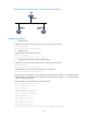
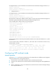
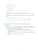
As shown in Figure 61, LB functions as the NTP server for multiple devices on a network segment and
synchronizes the time among multiple devices.
• LB’s local clock is to be used as a reference source, with the stratum level of 2.
• LB works in the broadcast server mode and sends out broadcast messages from Ten-Ethernet 0/0.1.
• Router A and Router C work in the broadcast client mode and receive broadcast messages through
their respective Ethernet 1/1.
Figure 61 Network diagram for NTP broadcast mode configuration
Configuration procedure
1. Configure LB .
# Specify the local clock as the reference source, with the stratum level of 2.
<LB> system-view
[LB] ntp-service refclock-master 2
# Configure LB to work in the broadcast server mode and send broadcast messages through
Ten-GigabitEthernet 0/0.1.
[LB] interface Ten-GigabitEthernet0/0.1
[LB-Ten-GigabitEthernet0/0.1] ntp-service broadcast-server
2. Configure Router C.