
R3204P16-HP Load Balancing Module System Management Configuration Guide-6PW101

110
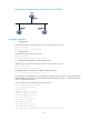
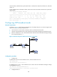
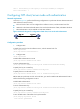
Figure 62 Network diagram for NTP multicast mode configuration
Configuration procedure
1. Configure LB:
# Specify the local clock as the reference source, with the stratum level of 2.
<LB> system-view
[LB] ntp-service refclock-master 2
# Configure LB to work in the multicast server mode and send multicast messages through Ethernet 1/1.
[LB] interface Ten-GigabitEthernet0/0.1
[LB-Ten-GigabitEthernet0/0.1] ntp-service multicast-server
2. Configure Router C:
# Configure Router C to work in the multicast client mode and receive multicast messages on Ethernet
1/1.
<RouterC> system-view
[RouterC] interface ethernet 1/1
[RouterC-Ethernet1/1] ntp-service multicast-client
Because Router C and LB are on the same subnet, Router C can receive the multicast messages from LB
without being enabled with the multicast functions and can be synchronized to LB.
# View the NTP status of Router C after clock synchronization.
[RouterC-Ethernet1/1] display ntp-service status
Clock status: synchronized
Clock stratum: 3
Reference clock ID: 3.0.1.31
Nominal frequency: 64.0000 Hz
Actual frequency: 64.0000 Hz
Clock precision: 2^7
Clock offset: 0.0000 ms
Root delay: 31.00 ms
Root dispersion: 8.31 ms
Peer dispersion: 34.30 ms
Reference time: 16:01:51.713 UTC Sep 19 2005 (C6D95F6F.B6872B02)
As shown above, Router C has been synchronized to LB and the clock stratum level of Router C is 3, while
that of LB is 2.