
R3204P16-HP Load Balancing Module System Management Configuration Guide-6PW101

114
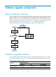
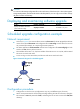
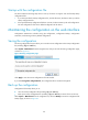
Figure 64 Network diagram for configuration of NTP broadcast mode with authentication
Configuration procedure
1. Configure LB A
# Specify the local clock as the reference source, with the stratum level of 3.
<LB A> system-view
[LB A] ntp-service refclock-master 3
# Configure NTP authentication.
[LB A] ntp-service authentication enable
[LB A] ntp-service authentication-keyid 88 authentication-mode md5 123456
[LB A] ntp-service reliable authentication-keyid 88
# Specify LB A as an NTP broadcast server, and specify an authentication key.
[LB A] interface Ten-GigabitEthernet0/0.1
[LB A-Ten-GigabitEthernet0/0.1] ntp-service broadcast-server authentication-keyid 88
2. Configure LB B:
# Configure NTP authentication.
<LB B> system-view
[LB B] ntp-service authentication enable
[LB B] ntp-service authentication-keyid 88 authentication-mode md5 123456
[LB B] ntp-service reliable authentication-keyid 88
# Configure LB B to work in the NTP broadcast client mode.
[LB B] interface Ten-GigabitEthernet0/0.1
[LB B-Ten-GigabitEthernet0/0.1] ntp-service broadcast-client
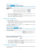
Now, LB B can receive broadcast messages through Ten-GigabitEthernet 0/0.1, and LB A can send
broadcast messages through Ten-GigabitEthernet 0/0.1. Upon receiving a broadcast message from LB A,
LB B synchronizes its clock to that of LB A.
# View the NTP status of LB B after clock synchronization.
[LB B-Ten-GigabitEthernet0/0.1] display ntp-service status
Clock status: synchronized
Clock stratum: 4
Reference clock ID: 3.0.1.31
Nominal frequency: 64.0000 Hz