
R3204P16-HP Load Balancing Module System Management Configuration Guide-6PW101

50
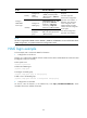
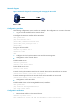
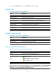
Network diagram
Figure 29 Network diagram for monitoring and managing the LB module
Configuration procedure
The following configuration uses a switch as an example. The configuration on a router is the same.
1. Log in to the LB module from the network device
# Configure the AUX user interface of the LB module.
<LB> system-view
[LB] user-interface aux 0
[LB-ui-aux0] authentication-mode none
[LB-ui-aux0] user privilege level 3
[LB-ui-aux0]
# Log in to the LB module.
<Switch> oap connect slot 3
Connected to OAP!
<LB>
2. Configure the clock synchronization timer and the monitoring timer
• Configuration on the network device
# Enable ACSEI server.
<Switch> system-view
[Switch] acsei server enable
# Enter ACSEI server view
[Switch] acsei server
# Set the clock synchronization timer from the network device to the LB module to 10 minutes
[Switch-acsei server] acsei timer clock-sync 10
# Set the monitoring timer from the network device to the LB module to 10 seconds
[Switch-acsei server] acsei timer monitor 10
• Configuration on the LB module
# Enable ACSEI client on the Ten-GigabitEthernet 0/0 interface.
<LB> system-view
[LB] interface Ten-GigabitEthernet0/0
[LB] acsei-client enable
Configuration verification
1. Restart the LB module on the network device.
<Switch> oap reboot slot 3
This command will recover the OAP from shutdown or other failed state.