HP Load Balancing Module Typical Configuration Examples Part number: 5998-2689 Document version: 6PW101-20120217
Legal and notice information © Copyright 2012 Hewlett-Packard Development Company, L.P. No part of this documentation may be reproduced or transmitted in any form or by any means without prior written consent of Hewlett-Packard Development Company, L.P. The information contained herein is subject to change without notice.
Contents Application scenarios ·················································································································································· 1 Application in a small- and medium-sized data center of a campus network ···························································· 1 Application in a large data center of carriers and portal websites ············································································ 2 Configuration guidelines ························
Subscription service ·············································································································································· 51 Related information ························································································································································ 51 Documents ······························································································································································
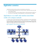
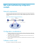
Application scenarios LB modules are primarily used to provide service load balancing in data centers. • For small- and medium-scale data centers of campus networks, which feature small access traffic, one LB module is enough. • For large-scale data centers of carriers and portal websites, which feature large access traffic, you can use one or two LB modules to provide stateful failover, improving data center availability.
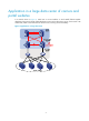
Application in a large data center of carriers and portal websites In a network shown in Figure 2, install one or two LB modules on each stateful failover-capable distribution layer switch. The LB module distributes services to the data center servers. If one switch or LB module fails, traffic can be delivered to another server, ensuring access availability.
Configuration guidelines • Make sure correct routing is configured for the switches and LB module. • The virtual service must be enabled. • For how to upgrade the LB module, see HP Security Modules Software Upgrade Guide. • Examples in this document use A7500 switches to cooperate with LB modules, and only the configuration related to the LB function is provided. These examples are also applicable to the A9500/A12500 switches and A8800 routers.
NAT-mode load balancing configuration example Network requirements The servers are in the private network and need to provide services for the users in the external network. Configure NAT-mode load balancing on the LB module installed on the A7503 to achieve load balancing between the private servers, which have a public IP address assigned to allow external users to access. Figure 3 Network diagram for NAT-mode load balancing Vlan-Int 10 192.168.10.1/30 Vlan-Int 110 202.38.1.2/24 PC 202.38.1.10 XGE0/0.
Configuration procedures NOTE: The following configurations are made on devices that are using default settings and verified in a lab environment. When using the following configurations on your devices in a live network, make sure they do not conflict with your current configurations to prevent potential negative impact on your network. Configurations on A7503 Configuration procedures 1. Create VLANs. # Create VLAN 10, VLAN 110, and VLAN 200.
Configuration file # vlan 10 //Connects to the LB module # vlan 110 //Connects to the external client description Outside # vlan 200 //Connects to servers description Servers # interface Vlan-interface10 description to LB ip address 192.168.10.1 255.255.255.252 # interface Vlan-in110 description Outside ip address 202.38.1.2 255.255.255.
• Use a console cable to connect the serial port of a configuration terminal (usually a PC) to the console port of the LB module. • Use a crossover Ethernet cable to connect the Ethernet port of the PC to GE 0/1, the default management interface of the LB module. Figure 4 Configuration environment for the LB module 3. Configure a terminal emulation program on the PC • On the PC, run a terminal emulation program, such as Terminal of Windows 3.X and HyperTerminal of Windows 9X and Windows XP.
Figure 5 LB module login page CLI configuration 1. Configuration procedures # Create Layer 3 subinterfaces. [Sysname] interface Ten-GigabitEthernet 0/0.10 [Sysname-Ten-GigabitEthernet0/0.10] vlan-type dot1q vid 10 [Sysname-Ten-GigabitEthernet0/0.10] ip address 192.168.10.2 255.255.255.252 [Sysname-Ten-GigabitEthernet0/0.10] quit [Sysname] interface Ten-GigabitEthernet 0/0.200 [Sysname-Ten-GigabitEthernet0/0.200] vlan-type dot1q vid 200 [Sysname-Ten-GigabitEthernet0/0.200] ip address 192.168.1.254 255.
Figure 6 Real service group page Click Add to enter the real service group configuration page. Type a name for the real service group, and select a scheduler algorithm, a health monitoring type, and a real service troubleshooting method. NOTE: • Health Monitoring Type is optional. If you do not select a health monitoring type, the LB module does not perform health monitoring for the real service.
NOTE: • You can use the default values for the port, weight, and connection limit. • Port 0 represents all ports. Figure 10 Add a real service • Type the real service name server1. • Type the real service IP address 192.168.1.1. • Set the port number to 80, weight to 100, and connection limit to 0. • Select the real service group http. • Click Apply. Follow similar steps to create real service server2. Figure 11 Real services server1 and server2 created successfully 3. Create a virtual service.
Figure 12 Virtual service page Click Add to enter the virtual service configuration page. Figure 13 Add a virtual service • Type VS as the virtual service name. • Type 172.16.1.100 as the virtual service IP address and select mask 32 (255.255.255.255). • Set port number to 0. • Select NAT as the forwarding mode. • Select the real service group http. • Select the Enable Virtual Service option. • Click Apply. Figure 14 Virtual service VS created successfully 4. Save the configuration.
Figure 15 Save the current configuration Verification Verification method 1. Use Avalanche to simulate multiple clients and two web servers. 2. Use the Weighted Round-Robin (WRR) algorithm and configure the weights for the two real services. 3. Use Avalanche to simulate a large number of users to access the servers. Verification result Access requests of the clients are distributed to the servers in proportions determined by the weights of the real services.
DR-mode load balancing configuration example Network requirements The servers are in the private network and need to provide services for the users in the external network. Configure DR-mode load balancing on the LB module installed on the A7503 to achieve load balancing between the private servers, which have a public IP address assigned to allow external users to access. Figure 16 Network diagram for DR-mode load balancing Configuration considerations • Configure the A7503 switch.
Configuration procedures NOTE: The following configurations are made on devices that are using default settings and verified in a lab environment. When using the following configurations on your devices in a live network, make sure they do not conflict with your current configurations to prevent potential negative impact on your network. Configurations on A7503 Configuration procedures 1. Create VLANs. # Create VLAN 110 and VLAN 200.
description Servers # interface Vlan-interface110 description Outside ip address 202.38.1.2 255.255.255.0 # interface Vlan-interface200 description Servers ip address 192.168.1.254 255.255.255.0 # interface GigabitEthernet4/0/16 port access vlan 110 # interface Ten-GigabitEthernet2/0/1 port access vlan 200 # interface Ten-GigabitEthernet2/0/2 # ip route-static 0.0.0.0 0.0.0.0 202.38.1.1 ip route-static 172.16.1.0 255.255.255.0 192.168.1.
Figure 17 LB module login page CLI configuration 1. Configuration procedures # Configure an IP address for the 10GE interface. [Sysname] interface Ten-GigabitEthernet 0/0 [Sysname-Ten-GigabitEthernet0/0] ip address 192.168.1.253 255.255.255.0 [Sysname-Ten-GigabitEthernet0/0] quit # Add a static route. [Sysname] ip route-static 0.0.0.0 0.0.0.0 192.168.1.254 2. Configuration file # interface Ten-GigabitEthernet0/0 port link-mode route ip address 192.168.1.253 255.255.255.0 # ip route-static 0.0.0.0 0.
Figure 19 Add a real service group NOTE: Health Monitoring Type is optional. If you do not select a health monitoring type, the LB module does not perform health monitoring for a real service. Click Apply. Figure 20 Real service group http created successfully 2. Create real services and add the real services to the real service group http. From the navigation tree, select Load Balance > Server Load Balance. Click the Real Service tab.
Figure 22 Add real service server1 • Type the real service name server1. • Type the real service IP address 192.168.1.1. • Set the port number to 80, weight to 100, and connection limit to 0. • Select the real service group http. • Click Apply. Follow similar steps to create real service server2. Figure 23 Real services server1 and server2 created successfully 3. Create a virtual service. From the navigation tree, select Load Balance > Server Load Balance. Click the Virtual Service tab.
Figure 25 Add a virtual service • Type VS as the virtual service name. • Type 172.16.1.100 as the virtual service IP address and select mask 32 (255.255.255.255). • Select protocol TCP. • Set port number to 0. • Select Direct Routing as the forwarding mode. • Select the real service group http. • Select the Enable Virtual Service option. • Click Apply. Figure 26 Virtual service VS created successfully 4. Save the configuration From the navigation tree, select System > Maintenance.
Figure 27 Save the current configuration Network adapter configurations on a server In DR-mode load balancing, you need to assign a loopback address on each server. The loopback address must be the same as the virtual service IP address configured on the LB module. If the server runs the Windows system, you need to add a loopback network adapter. The gateway address of the physical network adapter on the server is the IP address of the VLAN-interface 200 on the A7503 switch. 1.
Figure 29 Add Hardware Wizard step 1 • Select the Yes, I have already connected the hardware option, and click Next. Figure 30 Add Hardware Wizard step 2 • Select Add a new hardware device, and click Next.
Figure 31 Add Hardware Wizard step 3 • Select the Install the hardware that I manually select from a list (Advanced) option, and click Next. Figure 32 Add Hardware Wizard step 4 • Select Network adapters, and click Next.
Figure 33 Add Hardware Wizard step 5 • Select Microsoft Loopback Adapter in the Network Adapter column, and click Next. Figure 34 Add Hardware Wizard step 6 • Click Next.
Figure 35 Add Hardware Wizard step 7 • Click Finish. Figure 36 Add Hardware Wizard step 8 2.
Figure 37 Assign an IP address to the loopback adapter 3. Modify the loopback adapter attributes in the registry Open the Windows registry. Go to HKEY_LOCAL_MACHINE\SYSTEM\CurrentControlSet\Services\Tcpip\Parameters\Interfaces and find the adapter. Modify the value of SubnetMask to 255.255.255.255, disable the adapter, and then enable the adapter again.
Figure 38 Locate SubnetMask in the registry Figure 39 Modify the value of SubnetMask 26
Figure 40 Confirm the IP address and subnet mask of the loopback adapter Verification Verification method 1. Prepare two web servers, and configure a loopback network adapter for them. 2. Configure the scheduler algorithm as Round-Robin for the real service group on the LB module. 3. Use Avalanche to simulate a large number of clients to access the virtual service. Verification result The clients can access web services normally. Display the statistics on the LB module.
Gateway load balancing configuration example Network requirements In the networks where gateways (such as firewalls) processing capabilities have become the bottleneck, gateway load balancing can be adopted to balance the network traffic among multiple gateway devices.
Configuration procedures NOTE: The following configurations are made on devices that are using default settings and verified in a lab environment. When using the following configurations on your devices in a live network, make sure they do not conflict with your current configurations to prevent potential negative impact on your network. CAUTION: On the level-2 LB module LB_2, you must select the Keep Last-hop Information option on the Load Balance > Global Setting page.
[Sysname] interface Ten-GigabitEthernet 3/0/1 [Sysname-Ten-GigabitEthernet3/0/1] port link-type trunk [Sysname-Ten-GigabitEthernet3/0/1] port trunk permit vlan all [Sysname-Ten-GigabitEthernet3/0/1] quit 5. Add a static route. [Sysname] ip route-static 192.168.10.0 255.255.255.0 5.0.0.2 Configuration file # vlan 10 description Outside Vlan # vlan 23 to 24 # vlan 30 # interface Vlan-interface10 ip address 11.0.0.1 255.0.0.0 # interface Vlan-interface30 ip address 5.0.0.1 255.0.0.
system-view [Sysname] interface GigabitEthernet0/1 //Enter management interface view [Sysname-GigabitEthernet0/1] ip address 192.168.254.200 255.255.255.0 //Configure the IP address of the management interface as 192.168.254.200 [Sysname-GigabitEthernet0/1] quit save //Save the configuration 2. Enter http://192.168.254.200 in the IE address bar to enter the login page of the LB_1 module web interface.
port link-mode route # interface GigabitEthernet0/4 port link-mode route # interface Ten-GigabitEthernet0/0 port link-mode route # interface Ten-GigabitEthernet0/0.1 vlan-type dot1q vid 30 ip address 5.0.0.2 255.0.0.0 # interface Ten-GigabitEthernet0/0.23 vlan-type dot1q vid 23 ip address 6.0.0.2 255.0.0.0 # interface Ten-GigabitEthernet0/0.24 vlan-type dot1q vid 24 ip address 7.0.0.2 255.0.0.0 # ip route-static 0.0.0.0 0.0.0.0 5.0.0.1 Configuring gateway load balancing in the web interface 1.
Figure 44 Add a real service group Click Apply. Figure 45 Real service group http created 2. Create real services. From the navigation tree, select Load Balance > Server Load Balance. Click the Real Service tab. Figure 46 Real service page Click Add to enter the real service configuration page. NOTE: You can use the default values for the port, weight, and connection limit. Port 0 represents all ports.
Figure 47 Add a real service • Type the real service name FWT1. • Type the real service IP address 6.0.0.1. • Set the port number to 0, weight to 100, and connection limit to 1024. • Select the real service group http. • Click Apply. Follow similar steps to create real service FWT2. Figure 48 Real services FWT1 and FWT2 created 3. Create a virtual service. From the navigation tree, select Load Balance > Server Load Balance. Click the Virtual Service tab.
Figure 50 Add a virtual service • Type FWT as the virtual service name • Type 192.168.10.0 as the virtual service IP address and select mask 24 (255.255.255.0). • Select Any as the protocol type. • Set port number to 0. • Select Firewall Forwarding as the forwarding mode. • Select the real service group http. • Select the Enable Virtual Service option. • Click Apply. Figure 51 Virtual service FWT created Configurations on FW_1 Configuration procedures 1.
2. Configure IP addresses for interfaces. [Sysname] interface Ethernet0/0 [Sysname-Ethernet0/0] ip address 6.0.0.1 255.0.0.0 [Sysname-Ethernet0/0] quit [Sysname] interface Ethernet0/1 [Sysname-Ethernet0/1] ip address 8.0.0.1 255.0.0.0 [Sysname-Ethernet0/1] quit 3. Add the interfaces to security zones.
# firewall interzone trust untrust # firewall interzone trust DMZ # firewall interzone DMZ untrust # ip route-static 11.0.0.0 255.0.0.0 6.0.0.2 preference 60 ip route-static 192.168.10.0 255.255.255.0 8.0.0.2 preference 60 Configurations on FW_2 Configuration procedures 1. Configure a packet filtering firewall policy. [Sysname] firewall packet-filter enable [Sysname] firewall packet-filter default permit 2. Configure IP addresses for interfaces.
firewall zone trust add interface Ethernet0/0 set priority 85 # firewall zone untrust add interface Ethernet0/1 set priority 5 # firewall zone DMZ set priority 50 # firewall interzone local trust # firewall interzone local untrust # firewall interzone local DMZ # firewall interzone trust untrust # firewall interzone trust DMZ # firewall interzone DMZ untrust # ip route-static 11.0.0.0 255.0.0.0 7.0.0.2 preference 60 ip route-static 192.168.10.0 255.255.255.0 9.0.0.
[Sysname] interface Ten-GigabitEthernet 3/0/1 [Sysname-Ten-GigabitEthernet3/0/1] port link-type trunk [Sysname-Ten-GigabitEthernet3/0/1] undo port trunk permit vlan 1 [Sysname-Ten-GigabitEthernet3/0/1] port trunk permit vlan 23 to 24 100 [Sysname-Ten-GigabitEthernet3/0/1] quit Configuration file # vlan 23 to 24 # vlan 100 # interface GigabitEthernet4/0/1 port access vlan 100 # interface GigabitEthernet4/0/23 port access vlan 23 # interface GigabitEthernet4/0/24 port access vlan 24 # interface M-Ethernet0/0
Figure 52 LB_2 login page CLI configuration 1. Configuration procedures # Configure Layer 3 subinterfaces for the 10GE interface. [Sysname] interface Ten-GigabitEthernet 0/0.23 [Sysname-Ten-GigabitEthernet0/0.23] vlan-type dot1q vid 23 [Sysname-Ten-GigabitEthernet0/0.23] ip address 8.0.0.2 255.0.0.0 [Sysname-Ten-GigabitEthernet0/0.23] quit [Sysname] interface Ten-GigabitEthernet 0/0.24 [Sysname-Ten-GigabitEthernet0/0.24] vlan-type dot1q vid 24 [Sysname-Ten-GigabitEthernet0/0.24] ip address 9.0.0.2 255.0.
# interface Ten-GigabitEthernet0/0.23 vlan-type dot1q vid 23 ip address 8.0.0.2 255.0.0.0 # interface Ten-GigabitEthernet0/0.24 vlan-type dot1q vid 24 ip address 9.0.0.2 255.0.0.0 # interface Ten-GigabitEthernet0/0.100 vlan-type dot1q vid 100 ip address 192.168.10.207 255.255.255.0 Configuring gateway load balancing in the web interface 1. Save the last hop information From the navigation tree, select Load Balance > Global Configuration. Select the Keep Last-hop Information option and click Apply.
Server load balancing stateful failover configuration example Network requirements Configure NAT-mode load balancing on the LB module installed on the A7503 to achieve load balancing between the private servers, which have a public IP address assigned to allow external users to access. When access demand and traffic to the servers are large, you can configure stateful failover to improve network reliability, ensuring that users can access the servers.
Configuration procedures Configurations on A7503_1 Configuration procedures 1. Create VLANs. # Create VLAN 15 and VLAN 192. Sysname-view [Sysname] vlan 15 192 [Sysname] quit 2. Create VLAN interfaces and configure IP addresses for the interfaces, and then configure VRRP groups. [Sysname] interface Vlan-interface 15 [Sysname-Vlan-interface15] ip address 15.0.0.2 255.255.255.0 [Sysname-Vlan-interface15] vrrp vrid 15 virtual-ip 15.0.0.
Configuration file # vlan 15 # vlan 192 # interface Vlan-interface15 ip address 15.0.0.2 255.255.255.0 vrrp vrid 15 virtual-ip 15.0.0.4 vrrp vrid 15 priority 105 # interface Vlan-interface192 ip address 192.168.102.106 255.255.252.0 vrrp vrid 192 virtual-ip 192.168.102.
Logging in to LB_1 1. Configure an IP address for the management interface (GigabitEthernet 0/1). Make sure that the IP address of the management interface is in the same network segment of that of the PC. This step is optional. By default, the IP address of the management interface is 192.168.0.1/24. system-view [Sysname] interface GigabitEthernet0/1 //Enter management interface view [Sysname-GigabitEthernet0/1] ip address 192.168.0.1 255.255.255.
ip address 192.168.102.103 255.255.252.0 vrrp vrid 191 virtual-ip 192.168.102.125 vrrp vrid 191 priority 105 # ip route-static 0.0.0.0 0.0.0.0 192.168.102.123 Configuring stateful failover in the web interface For information about load balancing configuration, see Configurations on the LB module. 1. Create a real service group. From the navigation tree, select Load Balance > Server Load Balance. Click the Real Service Group tab.
Figure 58 Real service group telnet created 2. Create real services. From the navigation tree, select Load Balance > Server Load Balance. Click the Real Service tab. Figure 59 Real service page Click Add to enter the real service configuration page. Figure 60 Add a real service • Type the real service name Server1. • Type the real service IP 192.168.102.110. • Select the real service group telnet. • Click Apply. Follow similar steps to create real service Server2 and Server3.
Figure 61 Real services Server1, Server2, and Server3 created 3. Create a virtual service. From the navigation tree, select Load Balance > Server Load Balance. Click the Virtual Service tab. Figure 62 Virtual service page Click Add to enter the virtual service configuration page. Figure 63 Add virtual service telnet • Type telnet as the virtual service name • Type 11.0.0.1 as the virtual service IP address and select mask 32 (255.255.255.255). • Set port number to 0.
• Click Apply. Figure 64 Virtual service telnet created 4. Configure the stateful failover function. From the navigation tree, select High Availability > Stateful Failover. Select the Enable Stateful Failover option and select a backup type. Click the Modify Backup Interface button and select the backup interface(s). Figure 65 Configure the backup interface(s) Click Apply.
CAUTION: • After you configure stateful failover, save the configuration and then reboot the device to validate the stateful failover configuration. • After the stateful failover function takes effect on both LB modules, the stateful failover status changes to Synchronization. Configurations on the LB_2 module Configurations on LB_2 are the same as those on LB_1. See Configurations on the LB_1 module for reference. Verification Verification method Construct a network according to Figure 54.
Support and other resources Contacting HP For worldwide technical support information, see the HP support website: http://www.hp.
Conventions This section describes the conventions used in this documentation set. Command conventions Convention Description Boldface Bold text represents commands and keywords that you enter literally as shown. Italic Italic text represents arguments that you replace with actual values. [] Square brackets enclose syntax choices (keywords or arguments) that are optional. { x | y | ... } Braces enclose a set of required syntax choices separated by vertical bars, from which you select one.
Network topology icons Represents a generic network device, such as a router, switch, or firewall. Represents a routing-capable device, such as a router or Layer 3 switch. Represents a generic switch, such as a Layer 2 or Layer 3 switch, or a router that supports Layer 2 forwarding and other Layer 2 features. Represents a LB module. Port numbering in examples The port numbers in this document are for illustration only and might be unavailable on your device.
Index ACNRSV Network requirements,13 A Network requirements,42 Application in a large data center of carriers and portal websites,2 Network requirements,28 Network requirements,4 Application in a small- and medium-sized data center of a campus network,1 R C Related information,51 Configuration considerations,28 S Configuration considerations,4 Software version used,28 Configuration considerations,42 Software version used,13 Configuration considerations,13 Software version used,4 Configurati