
R3204P16-HP Load Balancing Module Typical Configuration Examples-6PW101

8
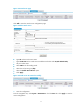
Figure 5 LB module login page
CLI configuration
1. Configuration procedures
# Create Layer 3 subinterfaces.
[Sysname] interface Ten-GigabitEthernet 0/0.10
[Sysname-Ten-GigabitEthernet0/0.10] vlan-type dot1q vid 10
[Sysname-Ten-GigabitEthernet0/0.10] ip address 192.168.10.2 255.255.255.252
[Sysname-Ten-GigabitEthernet0/0.10] quit
[Sysname] interface Ten-GigabitEthernet 0/0.200
[Sysname-Ten-GigabitEthernet0/0.200] vlan-type dot1q vid 200
[Sysname-Ten-GigabitEthernet0/0.200] ip address 192.168.1.254 255.255.255.0
[Sysname-Ten-GigabitEthernet0/0.200] quit
# Add a static route.
[Sysname] ip route-static 0.0.0.0 0.0.0.0 192.168.10.1
2. Configuration file
#
interface Ten-GigabitEthernet0/0.10
vlan-type dot1q vid 10
description to_A7503
ip address 192.168.10.2 255.255.255.252
#
interface Ten-GigabitEthernet0/0.200
vlan-type dot1q vid 200
description to Servers
ip address 192.168.1.254 255.255.255.0
#
ip route-static 0.0.0.0 0.0.0.0 192.168.10.1
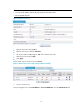
Configuring NAT-mode load balancing in the web interface
1. Create a real service group.
From the navigation tree, select Load Balance > Server Load Balance. Click the Real Service Group tab.