
R3204P16-HP Load Balancing Module Typical Configuration Examples-6PW101

29
Configuration procedures
NOTE:
The following configurations are made on devices that are using default settings and verified in a lab
environment. When usin
g
the followin
g
confi
g
urations on your devices in a live network, make sure the
y
do not conflict with your current configurations to prevent potential negative impact on your network.
CAUTION:
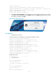
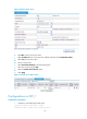
On the level-2 LB module LB_2, you must select the Keep Last-hop Information option on the Load
Balance > Global Setting page.
Configurations on A7503_1
Configuration procedures
1. Create VLANs.
# Create VLAN 10, 23, 24, 30.
<Sysname> Sysname-view
[Sysname] vlan 10
[Sysname-vlan10] quit
[Sysname] vlan 23 to 24
[Sysname] vlan 30
[Sysname-vlan30] quit
2. Create VLAN interfaces and configure IP addresses for the interfaces.
[Sysname] interface vlan 10
[Sysname-Vlan-interface10] ip address 11.0.0.1 255.0.0.0
[Sysname-Vlan-interface10] quit
[Sysname] interface vlan 30
[Sysname-Vlan-interface30] ip address 5.0.0.1 255.0.0.0
[Sysname-Vlan-interface30] quit
3. Assign interfaces to the VLANs.
[Sysname] interface GigabitEthernet 2/0/1
[Sysname-GigabitEthernet2/0/1] port access vlan 23
[Sysname-GigabitEthernet2/0/1] quit
[Sysname] interface GigabitEthernet 2/0/2
[Sysname-GigabitEthernet2/0/2] port access vlan 24
[Sysname-GigabitEthernet2/0/2] quit
[Sysname] interface GigabitEthernet 2/0/21
[Sysname-GigabitEthernet2/0/21] port access vlan 10
[Sysname-GigabitEthernet2/0/21] quit
4. Configure the 10GE interface that connects the LB module as a trunk interface, and assign it to all
VLANs.