
R3204P16-HP Load Balancing Module Typical Configuration Examples-6PW101

32
port link-mode route
#
interface GigabitEthernet0/4
port link-mode route
#
interface Ten-GigabitEthernet0/0
port link-mode route
#
interface Ten-GigabitEthernet0/0.1
vlan-type dot1q vid 30
ip address 5.0.0.2 255.0.0.0
#
interface Ten-GigabitEthernet0/0.23
vlan-type dot1q vid 23
ip address 6.0.0.2 255.0.0.0
#
interface Ten-GigabitEthernet0/0.24
vlan-type dot1q vid 24
ip address 7.0.0.2 255.0.0.0
#
ip route-static 0.0.0.0 0.0.0.0 5.0.0.1
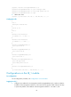
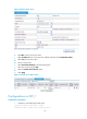
Configuring gateway load balancing in the web interface
1. Create a real service group.
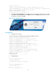
From the navigation tree, select Load Balance > Server Load Balance. Click the Real Service Group tab.
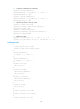
Figure 43 Real service group
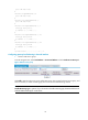
Click Add to enter the real service group configuration page. Type a name for the real service group, and
select a scheduler, a health monitoring type, and a real service troubleshooting method.
NOTE:
Health Monitoring Type is optional. If you do not select a health monitoring type, the LB module does no
t
perform health monitoring for a real service.