
R3204P16-HP Load Balancing Module Typical Configuration Examples-6PW101

50
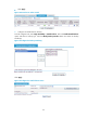
CAUTION:
• After you configure stateful failover, save the configuration and then reboot the device to validate the
stateful failover configuration.
• After the stateful failover function takes effect on both LB modules, the stateful failover status chan
g
es to
Synchronization.
Configurations on the LB_2 module
Configurations on LB_2 are the same as those on LB_1. See Configurations on the LB_1 module for
reference.
Verification
Verification method
Construct a network according to Figure 54. Use the client to access the servers through the LB module.
During user access, bring down the A7503 switch.
Verification result
The client can access the server through the main LB module. After the main switch is down, the backup
LB module takes over the access traffic, and the client can still access the servers normally.