HP High-End Firewalls Access Control Configuration Guide Part number: 5998-2648 Software version: F1000-A-EI&F1000-S-EI: R3721 F5000: F3210 F1000-E: F3171 Firewall module: F3171 Document version: 6PW101-20120719
Legal and notice information © Copyright 2012 Hewlett-Packard Development Company, L.P. No part of this documentation may be reproduced or transmitted in any form or by any means without prior written consent of Hewlett-Packard Development Company, L.P. The information contained herein is subject to change without notice.
Contents Configuring ACLs ························································································································································· 1 Overview············································································································································································ 1 ACL categories ····································································································································
Exporting and importing configuration ··············································································································· 51 Configuring service resources ··································································································································· 53 Overview········································································································································································· 53 Configuring
Configuring ASPF ···················································································································································· 103 Overview······································································································································································· 103 Configuring ASPF ·················································································································································
Configuring AAA ···················································································································································· 150 Feature and hardware compatibility ·························································································································· 150 AAA overview ······························································································································································ 150 RADIU
Overview······································································································································································· 247 Configuring FIPS··························································································································································· 247 Configuration consideration ·······························································································································
Configuring ACLs NOTE: The IPv6 ACL configuration is available only at the CLI. Overview An access control list (ACL) is a set of rules (or permit or deny statements) for identifying traffic based on criteria such as source IP address, destination IP address, and port number. You can use ACLs in QoS, firewall, routing, and other technologies for identifying traffic. The packet drop or forwarding decisions varies with modules that use ACLs. See the specific module for information about ACL application.
Match order The rules in an ACL are sorted in a specific order. When a packet matches a rule, the device stops the match process and performs the action defined in the rule. If an ACL contains overlapping or conflicting rules, the matching result and action to take depend on the rule order. The following ACL match orders are available: • config—Sorts ACL rules in ascending order of rule ID. A rule with a lower ID is matched before a rule with a higher ID.
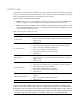
ACL rule numbering What is the ACL rule numbering step If you do not assign an ID to the rule you are creating, the system automatically assigns it a rule ID. The rule numbering step sets the increment by which the system automatically numbers rules. For example, the default ACL rule numbering step is 5. If you do not assign IDs to rules you are creating, they are numbered 0, 5, 10, 15, and so on. The wider the numbering step, the more rules you can insert between two rules.
Enable ACL acceleration in an ACL after you have finished editing ACL rules. ACL acceleration always uses ACL criteria that have been set before it is enabled for rule matching. It does not synchronize with any subsequent match criterion changes. Configuring an ACL in the Web interface Configuration task list Table 2 ACL configuration task list Task Remarks Required. Creating an ACL The category of the created ACL depends on the ACL number that you specify. Configuring a basic ACL rule Required.
Figure 1 ACL list Figure 2 ACL configuration page Table 3 Configuration items Item Description ACL Number Enter a number for the ACL. Select a match order for the ACL. Available values are: Match Order • Config—Sorts ACL rules in ascending order of rule ID. • Auto—Sorts ACL rules in depth-first order. Description Enter a description for the ACL. Configuring a basic ACL rule Select Firewall > ACL from the navigation tree.
Figure 3 List of basic ACL rules Figure 4 Basic ACL rule configuration page Table 4 Configuration items Item Description Select the Rule ID box and enter a number for the rule. Rule ID If you do not specify a rule number, the system automatically assigns one to the rule. IMPORTANT: If the rule already exists, the configuration overwrites the old rule. Select the operation to be performed for packets matching the rule. Operation • Permit—Allows matching packets to pass. • Deny—Denies matching packets.
Item Description Source IP Address Select the Source IP Address box and enter a source IP address and source wildcard, in dotted decimal notation. Source Wildcard VPN Instance Specify the VPN. If you select None, the rule applies to only non-VPN packets. Configuring an advance ACL rule Select Firewall > ACL from the navigation tree.
Figure 6 Advanced ACL rule configuration page Table 5 Configuration items Item Description Select the Rule ID box and enter a number for the rule. Rule ID If you do not specify the rule number, the system will assign one automatically. IMPORTANT: If the rule already exists, the configuration overwrites the old rule. Select the action to be performed for packets matching the rule. Operation • Permit—Allows matching packets to pass. • Deny—Denies matching packets. Select a time range for the rule.
Item Description Destination IP Address Select the Destination IP Address box and enter a destination IP address and destination wildcard, in dotted decimal notation. Destination Wildcard Specify the VPN. VPN Instance If you select None, the rule applies to only non-VPN packets. Select the protocol to be carried over by IP. Protocol If you select 1 ICMP, you can configure the ICMP message type and code. If you select 6 TCP or 17 UDP, you can configure the TCP or UDP specific items.
Figure 7 List of Ethernet frame header ACL rules Figure 8 Ethernet frame header ACL rule configuration page Table 6 Configuration items Item Description Select the Rule ID box and enter a number for the rule. Rule ID If you do not specify the rule number, the system will assign one automatically. IMPORTANT: If the rule already exists, the configuration overwrites the old rule. Select the operation to be performed for packets matching the rule. Operation • Permit—Allows matching packets to pass.
Item Description LSAP Type Select the LSAP Type box and specify the DSAP and SSAP fields in the LLC encapsulation by configuring the following two items: LSAP Wildcard • LSAP Type—Specifies the encapsulation format. • LSAP Wildcard—Specifies the LSAP mask. Protocol Type Select the Protocol Type box and specify the link layer protocol by configuring the following two items: • Protocol Type—Specifies a protocol type in Ethernet_II and Ethernet_SNAP Protocol Wildcard frames.
• Select Resource > Time Range from the navigation tree and then click Add. Create a time range. Figure 10 Creating a time range • Enter time in the Name field. • Select the Periodic Time Range box. • Select the Sun. and Sat. boxes. • Click Apply. Defining an ACL # Create a basic ACL. • Select Firewall > ACL from the navigation tree, and then click Add. Create ACL 2000 as shown in Figure 11. Figure 11 Creating an ACL • Enter the ACL number 2000. • Select the match order Config.
Figure 12 Configuring a rule to allow Host A to access Firewall • Select Permit from the Operation list. • Select the Source IP Address box and enter 192.168.1.2 and 0.0.0.0 respectively in the following fields. • Click Apply. # Create a rule to deny access of other hosts to Firewall on Saturday and Sunday. • On the page displaying the rules of ACL 2000, click Add. Figure 13 Configuring an ACL rule to deny access of other hosts to Firewall on Saturday and Sunday • Select Deny as the operation.
Figure 14 Configuring an ACL rule to allow other hosts to access Firewall • Select Permit. • Click Apply. NOTE: The three ACL rules must be configured in the shown order. Configuring service management # Associate HTTP service with ACL 2000. • Select Device Management > Service Management from the navigation tree. Associate HTTP service with ACL 2000. Figure 15 Associating HTTP service with ACL 2000 • Click the + sign before HTTP to expand the configuration area. • Enter 2000 in the ACL field.
Configuring an ACL at the CLI ACL configuration task list Complete the following tasks to configure an ACL: Task Remarks Configuring a basic ACL Required. Configure at least one task. NOTE: Configuring an advanced ACL • Within an ACL, the permit or deny statement of each rule Configuring an Ethernet frame header ACL must be unique. If the ACL rule you are creating or editing has the same deny or permit statement as another rule in the ACL, your creation or editing attempt will fail.
Step Command Remarks 5. Create or edit a rule. rule [ rule-id ] { deny | permit } [ counting | fragment | logging | source { sour-addr sour-wildcard | any } | time-range time-range-name | vpn-instance vpn-instance-name ] * 6. Configure or edit a rule description. rule rule-id comment text By default, an IPv4 basic ACL does not contain any rule. To create or edit multiple rules, repeat this step.
Configuring an advanced ACL Configuring an IPv4 advanced ACL IPv4 advanced ACLs match packets based on source IP addresses, destination IP addresses, packet priorities, protocols over IP, and other protocol header information, such as TCP/UDP source and destination port numbers, TCP flags, ICMP message types, and ICMP message codes. Compared to IPv4 basic ACLs, IPv4 advanced ACLs allow more flexible and accurate filtering. To configure an IPv4 advanced ACL: Step 1. Enter system view.
source port number, TCP/UDP destination port number, ICMPv6 message type, and ICMPv6 message code. Compared to IPv6 basic ACLs, IPv6 advanced ACLs allow more flexible and accurate filtering. To configure an IPv6 advanced ACL: Step 1. Enter system view. Command Remarks system-view N/A By default, no ACL exists. Create an IPv6 advanced ACL and enter its view. acl ipv6 number acl6-number [ name acl6-name ] [ match-order { auto | config } ] Configure a description for the IPv6 advanced ACL.
Step Command Remarks By default, no ACL exists. Create an Ethernet frame header ACL and enter its view. 2. 3. 4. 5. acl number acl-number [ name acl-name ] [ match-order { auto | config } ] Ethernet frame header ACLs are numbered in the range 4000 to 4999. You can use the acl name acl-name command to enter the view of a named Ethernet frame header ACL. Optional. Configure a description for the Ethernet frame header ACL. description text Set the rule numbering step.
Copying an IPv6 ACL Step Command 1. Enter system view. system-view 2. Copy an existing IPv6 ACL to generate a new one of the same category. acl ipv6 copy { source-acl6-number | name source-acl6-name } to { dest-acl6-number | name dest-acl6-name } Enabling ACL acceleration for an IPv4 ACL Step 1. Enter system view. Command Remarks system-view N/A Disabled by default. 2. Enable ACL acceleration for an IPv4 ACL. The ACL must exist.
ACL configuration example NOTE: IPv4 ACL application usually works with NAT. For IPv4 ACL configuration examples, see NAT Configuration Guide. Network requirements A company interconnects its departments through Firewall. Configure an ACL to: • Permit access from the President's office at any time to the financial database server. • Permit access from the Financial department to the database server only during working hours (from 8:00 to 18:00) on working days.
[Firewall] firewall ipv6 enable [Firewall] interface GigabitEthernet 0/1 [Firewall-GigabitEthernet0/1] firewall packet-filter ipv6 3000 outbound [Firewall-GigabitEthernet0/1] quit Verifying the configuration # Ping the database server from a PC in the Financial department during the working hours. (All PCs in this example use Windows XP).
Configuring security zones You can configure security zones only in the Web interface. To use an interface as a service interface, you must add it to a security zone that is not the management zone before configuring relevant service functions. Overview Traditional firewall/router policies are configured based on packet inbound and outbound interfaces on early dual-homed firewalls.
Figure 17 Zone classification Zone configuration task list Task Remarks Optional Selecting the virtual device to which the specified zone belongs Select Device Management > Virtual Device > Device Selection from the navigation tree to enter the virtual device selection page. For more information, see System Management and Maintenance Configuration Guide. By default, a virtual root device is used.
Figure 18 Zone list 2. Click Add. Figure 19 Creating a zone 3. Configure the zone as described in Table 7. 4. Click Apply. Table 7 Configuration items Item Description Zone ID Set the zone ID. Zone Name Set the zone name. Preference Share Set the preference of a zone. By default, packets from a high priority zone to a low priority zone are allowed to pass. Set whether the specified zone can be referenced by other virtual devices. Configuring a zone member 1.
Figure 20 Modifying a zone 3. Configure the zone as described in Table 8. 4. Click Apply. Table 8 Configuration items Item Description Zone ID Display the zone ID. Zone Name Display the zone name.
Item Description Set the preference of the specified zone Preference By default, packets from a high priority zone to a low priority zone are allowed to pass. Share Set whether the specified zone can be referenced by other virtual devices. Virtual Device Display the virtual device to which the zone belongs. Set the interfaces to be added to the zone.
Figure 21 Network diagram Firewall GE 0 /1 Trust GE 0/3 GE 0/2 Internet Untrust DMZ FTP server WWW server Configuration consideration By default, the system has created the Trust, DMZ and Untrust zones, and you only need to configure them and deploy them. Configuration procedure 1. Configure the Trust zone, and add interface GigabitEthernet 0/1 to the Trust zone: a. Select Device Management > Zone from the navigation tree. b. Click the icon of the Trust zone.
Figure 22 Configuring the Trust zone c. Select the GigabitEthernet 0/1 box. d. Click Apply. 2. Configure the DMZ zone, and add interface GigabitEthernet 0/2 to the DMZ zone: a. Click Back to return to the page for displaying zones. b. Click the icon of the DMZ zone.
Figure 23 Configuring the DMZ zone c. Select GigabitEthernet 0/2. d. Click Apply. 3. Configure the Untrust zone and add interface GigabitEthernet 0/3 to the Untrust zone. a. Click Back to return to the page for displaying zones. b. Click the icon of the Untrust zone to perform the following configurations.
Figure 24 Configuring the Untrust zone c. Select GigabitEthernet 0/3. d. Click Apply.
Configuring service management NOTE: The interzone policy configuration is available only in the web interface. Overview The service management module provides six types of services: FTP, Telnet, SSH, SFTP, HTTP and HTTPS. You can enable or disable the services as needed. In this way, the performance and security of the system can be enhanced, thus secure management of the device can be achieved.
• Encrypts the data exchanged between the HTTPS client and the device to ensure data security and integrity, thus realizing the security management of the device; • Uses digital certificates to verify servers to prevent clients from accessing unauthorized servers, thus protecting significant information such as administrator account information. Configuring service management 1. Select Device Management > Service Management from the navigation tree. The service management configuration page appears.
Item Description Set the port number for HTTP service. Port Number You can view this configuration item by clicking the expanding button in front of HTTP. IMPORTANT: When you modify a port, make sure that the port is not used by other service. ACL Enable HTTPS service Associate the HTTP service with an ACL. Only the clients that pass the ACL filtering are permitted to use the HTTP service. You can view this configuration item by clicking the expanding button in front of HTTP.
Figure 26 Network diagram Configuring the time range 1. Select Resource > Time Range from the navigation tree . 2. Click Add. The page for adding time range appears. Figure 27 Create a time range 3. Create a time range as shown in Figure 27. a. Enter time in the Name field. b. Select the Periodic Time Range box. c. 4. Select the Sun. and Sat. checkboxes. Click Apply. Creating a basic ACL. 1. Select Firewall > ACL from the navigation tree. 2. Click Add. The page for adding ACL appears.
Figure 28 Creating an ACL 3. Create ACL 2000 as shown in Figure 28. a. Enter the ACL number 2000. b. Select the match order Config. c. Click Apply. Creating a rule to allow Host A to access Firewall 1. Click the 2. Click Add. icon of ACL 2000 from the ACL list in the Operation column. The ACL rule configuration page appears. Figure 29 Configure a rule to allow Host A to access Firewall 3. Create an ACL rule as shown in Figure 29. a. Select Permit from the Operation box. b.
a. Select Deny as the operation. b. Select time as the time range. c. Select Source IP Address box. d. Enter 192.168.1.0 in the Source IP Address field. e. Enter 0.0.0.255 in the Source Wildcard field. 3. Sunday Click Apply. Figure 30 Configuring an ACL rule to disable other hosts from accessing Firewall on Saturday and Configuring an ACL rule to allow other hosts to access Firewall 1. Click Add on the page displaying rules of ACL 2000. 2. Select Permit as the operation. 3. Click Apply.
b. Enter 2000 in the ACL field. 3. Click Apply. Figure 32 Associating HTTP service with ACL 2000 HTTPS configuration example Network requirements As shown in Figure 33, Host can access and control Firewall through web pages. To avoid malicious users from accessing and controlling Firewall, users use HTTPS to access web pages on Firewall. SSL is used to authenticate servers, preventing data eavesdropping and data modification.
Configuring a PKI entity 1. Select VPN > Certificate Management > Entity from the navigation tree. 2. Click Add. The page for adding a PKI entity appears. Figure 34 Adding a PKI entity 3. Configure a PKI entity as shown in Figure 34. a. Enter en as the PKI entity name. b. Enter http-server1 as the common name. c. 4. Enter ssl.security.com in the FQDN field. Click Apply. Creating a PKI domain 1. Select VPN > Certificate Management > Domain from the navigation tree. 2. Click Add.
Figure 35 Add a PKI domain 3. Add a PKI domain as shown in Figure 35. a. Enter 1 as the PKI domain name. b. Enter CA server as the CA identifier. c. Select en as the local entity. d. Select RA as the authority for certificate request. e. Enter http://10.1.2.2/certsrv/mscep/mscep.dll as the URL for certificate request. 4. Click Apply. 5. Click OK when the system displays "Fingerprint of the root certificate not specified. No root certificate validation will occur.
2. Click Retrieve Cert. The page for retrieving a certificate appears. 3. Retrieve the CA certificate as shown in Figure 37. a. Select 1 as the PKI domain. b. Select CA as the certificate type. 4. Click Apply. Figure 37 Retrieving the certificate Requesting a local certificate 1. Select VPN > Certificate Management > Certificate from the navigation tree. 2. Click Request Cert. The page for requesting a certificate appears. Figure 38 Requesting a certificate 3. Select 1 as the PKI domain name.
Figure 39 Enabling HTTPS service 2. Select the Enable HTTPS service box. 3. Select CN=http-server1 from the certificate list. 4. Click Apply. Adding a local user 1. Select User > Local user from the navigation tree. 2. Click Add. The page for adding a local user appears. Figure 40 Adding a local user 3. Configure the local user as shown in Figure 40. a. Enter usera in the User Name field. b. Select the user privilege level Configure. c. Specify the service type as Web. d.
Verifying the configuration Open an Internet browser on Host and enter https://10.1.1.1 in the address bar to enter the web login interface. Enter the username usera, password 123, and verification code, and then click Log in. You can access Firewall.
Configuring address resources NOTE: The address resource configuration is available only in the web interface. Address resource overview Address resources are classified into four categories: IP address resource, IP address group resource, MAC address resource, and MAC address group resource. They can be referenced by interzone policies to define packet match criteria.
Figure 42 Host address resource configuration page Table 10 Configuration items Item IP Address Domain Name Description Select either of them as the address resource form. Specify the name for the host address resource. Name IMPORTANT: All resources (excluding the time range resources) must have unique names. Description Describe the host address resource in brief. Specify the IP addresses for the host address resource.
Figure 43 Address range resource list Figure 44 Address range resource configuration page Table 11 Configuration items Item Description Specify the name for the address range resource. Name IMPORTANT: All resources (excluding the time range resources) must have unique names. Description Describe the address range resource in brief. Address Range Specify a start IP address and an end IP address to define an address range. Specify the IP addresses to be excluded.
Configuring a subnet address resource Select Resource > Address > IP Address from the navigation tree, and click the Subnet tab to enter the subnet address resource list page, as shown in Figure 45. Then, click Add to enter the subnet address resource configuration page, as shown in Figure 46. Figure 45 Subnet address resource list Figure 46 Subnet address resource configuration page Table 12 Configuration items Item Description Specify the name for the subnet address resource.
Item Description Specify the IP addresses to be excluded. • Type an IP address in the text box next to the Add button, and then click Add to Exclude IP Address add it to the excluded IP address list. • Select one or more IP addresses in the excluded IP address list, and then click Remove to remove them from the list. Configuring an IP address group resource Select Resource > Address > Address Group from the navigation tree to enter the IP address group display page, as shown in Figure 47.
Table 13 Configuration items Item Description Specify the name for the address group resource. Name IMPORTANT: All resources (excluding the time range resources) must have unique names. Description Describe the address group resource in brief. Add or remove IP address resources: • Select one or more IP address resources from the Available Group Members list and then click the << button to add them to the Group Members list.
Table 14 Configuration items Item Description Specify the name for the MAC address resource. Name IMPORTANT: All resources (excluding the time range resources) must have unique names. Description Describe the MAC address resource in brief. Add or remove MAC address resources: • Type a MAC address in the text box next to the Add button, and then click Add to MAC Address add it to the MAC List. • Select one or more MAC addresses in the MAC list, and then click Remove to remove them from the list.
Figure 52 MAC address group configuration page Table 15 Configuration items Item Description Specify the name for the MAC address group resource. Name IMPORTANT: All resources (excluding the time range resources) must have unique names. Description Describe the MAC address group resource in brief. Add or remove MAC address group resources: • Select one or more MAC address resources from the Available Group Members list and then click << to add them to the Group Members list.
Figure 53 Export configurations Importing resource configurations On any of the resource list page, click Import to bring up the dialog box as shown in Figure 54. Click Browse, and then choose the configuration file and click Apply to import all configurations in the file.
Configuring service resources NOTE: The service resource configuration is available only in the web interface. Overview A service resource defines a service by specifying the protocol to be carried by IP and the protocol-specific items. It may be referenced by an inter-zone policy as a packet match criterion. Service resources fall into the following categories: • Default service resources—Created by the device during initialization. • Customized service resource—Created manually.
Figure 55 Default service resource list Configuring a customized service resource 1. Select Resource > Service > Customized Service from the navigation tree. All existing customized service resources are displayed. Figure 56 Customized service resource list 2. Click Add. The customized service resource configuration page appears.
Figure 57 Customized service resource configuration page 3. Configure the parameters as described in Table 16. 4. Click Apply. Table 16 Configuration items Item Description Specify a unique name for the customized service resource. Name IMPORTANT: Service and address resource names must be unique. Description Type a description for the customized service resource. Source Port TCP UDP • To define a single port, type the same port numbers in the two fields in a row.
Table 17 ICMP message names and their message types and codes ICMP message name Type Code echo 8 0 echo-reply 0 0 fragmentneed-DFset 3 4 host-redirect 5 1 host-tos-redirect 5 3 host-unreachable 3 1 information-reply 16 0 information-request 15 0 net-redirect 5 0 net-tos-redirect 5 2 net-unreachable 3 0 parameter-problem 12 0 port-unreachable 3 3 protocol-unreachable 3 2 reassembly-timeout 11 1 source-quench 4 0 source-route-failed 3 5 timestamp-reply 14
Figure 59 Service group resource configuration page 3. Configure the parameters as described in Table 18. 4. Click Apply. Table 18 Configuration items Item Description Specify a unique name for the service group resource. Name IMPORTANT: Service and address resource names must be unique. Description Type a description for the service group resource.
NOTE: For more information, see "Configuring address resources" and "Configuring interzone policies." Exporting configuration 1. On the customized or service group resource list page, click Export. The page for exporting configurations appears as shown in Figure 60. 2. Choose the types of configurations you want to export by selecting the boxes and then click Apply. 3. On the pop-up dialog box, click Save. 4.
Configuring time range resources Overview A time range resource defines a time range, which can be referenced by an ACL or an interzone policy to control when a rule is effective. The following basic types of time range are available: • Periodic time range—Recurs periodically on a day or days of the week. • Absolute time range—Represents only a period of time and does not recur. You can create a maximum of 256 time ranges, each with a maximum of 32 periodic statements and 12 absolute statements.
Figure 63 Time range resource configuration page Table 19 Configuration items Item Description Name Enter the name for the time range resource. Periodic Time Range Start Time Set the start time of the periodic time range, in the hh:mm format (24-hour clock). End Time Set the end time of the periodic time range, in the hh:mm format (24-hour clock). The end time must be greater than the start time. Sun., Mon., Tues., Wed., Thurs., Fri., and Sat.
Step 3. Display the configuration and status of one or all time ranges. Command Remarks display time-range { time-range-name | all } [ | { begin | exclude | include } regular-expression ] Optional. Available in any view. Configuration guidelines If the selected time range resource includes the current time, the time range is displayed as "Active" in the time range resource list. Otherwise, the time range is displayed as "Inactive".
Interzone policy configuration NOTE: The interzone policy configuration is available only in the web interface. Interzone policy overview Interzone policies, based on ACLs, are used for identification of traffic between zones. An interzone policy references one ACL for a pair of source zone and destination zone. This ACL contains a group of ACL rules, each of which permits or denies packets matching the match criteria.
Configuring an interzone policy Configuration task list NOTE: Before configuring an Interzone policy, be sure to configure the zones. For information about zone configuration, see "Zone configuration." Table 20 Interzone policy configuration task list Task Remarks Required Configuring an interzone policy rule Use either method. By default, no interzone policy rules or interzone policy groups are present in the system.
Figure 64 List of interzone policy rule list Table 21 Operations you can perform on the list Field Source Address/Destination Address/Source MAC/Destination MAC Service Content Filtering Policy Template Operation Click an address (except any_address and any_mac) to enter the address resource configuration page, where you can view and modify the address resource configuration. For information about address resources, see "Address resource configuration.
Figure 65 Interzone policy rule configuration page Table 22 Configuration items Item Description Source Zone Specify the source zone for the interzone policy. Dest Zone Specify the destination zone for the interzone policy. Description Describe the ACL rule in brief. Configure a source address resource for the rule by creating an address resource or referencing an existing address resource. • If you select the New IP Address option, you need to specify an IP address and Source IP Address wildcard.
Item Description Select a service resource for the rule. Service You can select one service resource from the list or click Multiple to select more. The available service resources are configured in the page you enter by selecting Resource > Service. For more information, see "Service resource configuration." Select the operation to be performed for packets matching the rule. Filter Action • Permit: Allows packets matching the rule to pass. • Deny: Drops packets matching the rule.
Item Description Specify whether to create another rule after finishing this one. • If you select this box, you will enter the interzone policy rule configuration page Continue to add next rule after clicking Apply, with the source zone and destination zone selected for the last rule. • If you do not select this box, you will see the list of interzone policy rule after clicking Apply.
Exporting and importing configuration Select Firewall > Security Policy > Interzone Policy from the navigation tree to enter the interzone policy rule list page, as shown in Figure 64. • Click Export to bring up the dialog box as shown in Figure 67. Select the types of configurations you want to export by selecting the boxes, and then click Apply. On the pop-up dialog box, click Save.
Table 23 Operations you can perform on the list Field Operation Referenced ACLs Click an ACL to enter the ACL configuration page, where you can view, create, and delete rules in the ACL. For information about ACL configuration, see "ACL configuration." Status • shows that the interzone policy group is enabled. You can click Disable to disable the interzone policy group. • shows that the interzone policy group is disabled. You can click Enable to enable the interzone policy group.
results matching the search conditions. Click Reset in the Operation column to clear the packets statistics of the related interzone policy and at this time the system starts to perform statistics again.
Figure 73 Network diagram Method 1: Configuring an interzone policy rule # Create a periodic time range from 8:00 to 18:00 on working days (from Monday through Friday). • Select Resource > Time Range from the navigation tree, and then click Add. Figure 74 Configure a time range • Type worktime in the Name field. • Select the Periodic Time Range box. • Set the start time to 8:00. • Set the end time to 18:00. • Select the Mon., Tues., Wed., Thurs., and Fri., boxes. • Click Apply.
Figure 75 Configure an IP address resource • Select the IP Address option. • Type public as the name. • Type 10.1.1.12 as the IP address. Then click Add to add this address to the IP list. • Click Apply. # Configure an access rule for host public to access the external network at any time. • Select Firewall > Security Policy > Interzone Policy from the navigation tree, and then click Add.
• Select Trust as the source zone and Untrust as the destination zone. • Select public as the address. • Select Permit as the filter action. • Select the Status box. • Select the Continue to add next rule box. • Click Apply. # Configure an access rule to deny the access of all the other hosts to the external network during working time.
Figure 78 Configure a time range • Type worktime in the Name field. • Select the Periodic Time Range box. • Set the start time to 8:00. • Set the end time to 18:00. • Select the Mon., Tues., Wed., Thurs., and Fri., boxes. • Click Apply. # Create ACL 3000. • Select Firewall > ACL from the navigation tree, and then click Add. Figure 79 Configure ACL 3000 • Type 3000 in the ACL Number field. • Select Config as the match order. • Click Apply.
Figure 80 Allow the host Public to access the external network at any time • Select Permit as the operation. • Select the Source IP Address box, and type 10.1.1.12 and 0.0.0.0 in the following fields. • Click Apply. # Configure a rule to deny access of all the other hosts to the external network during working time. • On the page that lists the rules, click Add.
Figure 81 Deny all the other hosts' access to the external network during working time • Select Deny as the operation. • Select the time range worktime. • Click Apply. # Configure the interzone policy group. • Select Firewall > Security Policy > Interzone Policy Group from the navigation tree to enter the interzone policy group list page, as shown in Figure 69. Then click Add to enter the interzone policy group configuration page.
• Select Trust as the source zone. • Select Untrust as the destination zone. • Select 3000 under Available ACLs, and click << to add it to the selected ACL list. • Select the enable box. • Click Apply. Firewall policy configuration wizard Overview The firewall policy configuration wizard provides a way to configure firewall policies for virtual devices easily. It can also help you to configure interzone policy parameters.
Figure 83 Firewall policy configuration wizard: 1/7 3. Configure the items on the page. Table 27 Configuration items item Description Source Zone Specify the source zone of the firewall policy. Destination Zone Specify the destination zone of the firewall policy. 4. Click Next to enter the second page of the firewall policy configuration wizard. Figure 84 Firewall policy configuration wizard: 2/7 5. Configure the items on the page.
Table 28 Configuration items Item Description Specify the action to be taken for packets matching the firewall policy: • Permit—Allows matched packets to pass. Filter Action • Deny—Drops matched packets. Specify the content filtering template to be applied to the packets that match the firewall policy. Content Filter Policy 6. Click Next to enter the third page of the firewall policy configuration wizard. Figure 85 Firewall policy configuration wizard: 3/7 7. Configure the items on the page.
Figure 86 Firewall policy configuration wizard: 4/7 9. Configure the items on the page. Table 30 Configuration items item Description Service (Group) Specify the service resource for the firewall policy. 10. Click Next to enter the fifth page of the firewall policy configuration wizard.
Figure 87 Firewall policy configuration wizard: 5/7 11. Configure the items on the page. Table 31 Configuration items Item Description Time Range Specify the time range resource for the firewall policy. 12. Click Next to enter the sixth page of the firewall policy configuration wizard.
Figure 88 Firewall policy configuration wizard: 6/7 13. Configure the items as described in Table 32. Table 32 Configuration items Item Description Enable Syslog Function Specify whether to keep a log of matched packets. 14. Click Next to enter the seventh page of the firewall policy configuration wizard.
Figure 89 Firewall policy configuration wizard: 7/7 15. Select whether to save the current configuration to the configuration files to be used at next startup (including a cfg file and xml file), check that the settings are what you want, and then select the page to jump to: • Interzone policy page—Jumps to the page you can enter by selecting Firewall > Security Policy > Interzone Policy from the navigation tree.
Managing sessions Overview The session management feature is designed to manage sessions of applications such as network address translation (NAT), application specific packet filter (ASPF), and intrusion protection. This feature regards packet exchanges at the transport layer as sessions and updates the status of sessions or ages out sessions according to the information in packets. Session management allows multiple features to process the same service packet respectively.
• Supporting persistent sessions. You can specify TCP sessions meeting certain criteria as persistent sessions. The aging time of a persistent session does not vary with the session state transitions, neither will a persistent session be removed because no packets match it.
Displaying and maintaining session management information Task Remarks Displaying session table information Display the session table information of the current virtual device. Displaying session statistics Task Remarks Displaying global session statistics Display the global session statistics. Enable or disable session statistics collection based on source/destination security zone or source/destination IP address.
Figure 90 Session configuration 2. Configure the parameters as described in Table 33. 3. Click Apply.
Table 33 Configuration items Item Description Enable or disable unidirectional traffic detection. • With unidirectional traffic detection enabled, session management Enable unidirectional traffic detection processes both the unidirectional and bidirectional traffic. • With unidirectional traffic detection disabled, session management processes only the bidirectional traffic. Specify the ID of an ACL Only one ACL can be referenced as the persistent session rule, and the last referenced ACL takes effect.
Displaying session table information 1. Select Firewall > Session Table > Session Summary from the navigation tree. The session table appears as shown in Figure 91.
Table 35 Field description Field Description Protocol Transport layer protocol, which can be TCP, UDP, ICMP, or RAWIP Session status, which can be: • Accelerate • SYN • TCP-EST • FIN State • UDP-OPEN • UDP-READY • ICMP-OPEN • ICMP-CLOSED • RAWIP-OPEN • RAWIP-READY TTL Remaining lifetime of the session Initiator: VD / ZONE / VPN / IP / PORT The initiator's virutal device/security zone/VPN instance/IP address/port number Responder: VD / ZONE / VPN / IP / PORT The responder's virual device/security
Figure 93 Global session statistics Table 36 Field description Item Description Current Session(s) Total number of sessions of the system Current TCP Session(s) Total number of current TCP half-open connections, TCP half-close connections, and full TCP connections in the system Current TCP Half-Open Session(s) Number of current TCP half-open connections in the system Current TCP Half-Close Session(s) Number of current TCP half-close connections in the system Current UDP Session(s) Number of curr
Item Description RAWIP Session Establishment Rate RAWIP session establishment rate in a 1-second sampling interval Received TCP Packet(s) Number of TCP packets received Received TCP Byte(s) Number of TCP bytes received Received UDP Packet(s) Number of UDP packets received Received UDP Byte(s) Number of UDP bytes received Received ICMP Packet(s) Number of ICMP packets received Received ICMP Byte(s) Number of ICMP bytes received Received RAWIP Packet(s) Number of RAWIP packets received Recei
Displaying session statistics per IP address 1. Select Firewall > Session Table > Statistics from the navigation tree. 2. Click the IP Statistics tab. 3. Select the direction, specify the IP address, select VPN instance/VLAN ID/INLINE ID, and click Search. The matched session statistics are displayed.
Field Description RAWIP Connection Rate RAWIP connection establishment rate in a 5-second sampling interval TCP Packet Count Number of TCP packets TCP Byte Count Number of TCP bytes UDP Packet Count Number of UDP packets UDP Byte Count Number of UDP bytes ICMP Packet Count Number of ICMP packets ICMP Byte Count Number of ICMP bytes RAWIP Packet Count Number of RAWIP packets RAWIP Byte Count Number of RAWIP bytes Displaying session statistics based on security zone To display security zon
Field Description TCP Half-Open Connection Count Number of TCP half-open connections TCP Half-Close Connection Count Number of TCP half-close connections TCP Connection Rate TCP connection establishment rate in a 5-second sampling interval UDP Connection Count Number of full UDP connections UDP Connection Rate UDP connection establishment rate in a 5-second sampling interval ICMP Connection Count Number of full ICMP connections ICMP Connection Rate ICMP connection establishment rate in a 5-se
Configuring session aging timers based on application layer protocol types Aging timers set in this task apply only to the sessions in READY/ESTABLISH state. For sessions in READY (with UDP) or ESTABLISH (with TCP) state, you can set the session aging timer according to the type of the application layer protocol to which the sessions belong. To set session aging times based on application layer protocol types: Step Command 1. Enter system view. system-view 2.
Step Command Remarks 1. Enter system view. system-view N/A 2. Specify the persistent session rule. session persist acl acl-number [ aging-time time-value ] Not specified by default. NOTE: • A persistent session rule can reference only one ACL. • Only TCP sessions in ESTABLISHED state can be specified as persistent sessions. Clearing sessions To clear sessions: Task Command Remarks Clear sessions.
Configuration guidelines When you configure session management, follow these guidelines: • If the number of sessions is too large, for example, more than 800,000 sessions, you are not recommended to set small values for aging times of the protocol states and application layer protocols. Otherwise, the responses of the console will be slow. • Only TCP sessions in ESTABLISHED state can be specified as persistent sessions.
Configuring virtual fragment reassembly The virtual fragment reassembly configuration is available only in the Web interface. Overview To prevent service modules (such as IPSec, NAT and firewall) from processing packet fragments that arrive out of order, you can enable the virtual fragment reassembly feature. This feature can virtually reassemble the fragments of a datagram through fragment checking, sequencing and caching so as to make sure that fragments arrive at service modules in order.
3. Click Apply. Table 40 Configuration items Item Description Security Zone Specify a security zone to be configured with virtual fragment reassembly. Enable Virtual Fragment Reassembly Select the box to enable the virtual fragment reassembly feature. Specify max number of concurrent reassemblies Specify the maximum number of concurrent reassemblies. When this value is reached, the firewall discards all subsequent packets and sends a syslog message.
a. Select Firewall > NAT Policy > Static NAT from the navigation tree. b. Click Add in the Static Address Mapping area. c. Enter 1.1.1.1 for Internal IP Address. d. Enter 2.2.2.3 for Global IP Address. e. Click Apply. Figure 99 Adding a static address mapping 3. Enable static NAT on GigabitEthernet 0/1: a. Click Add in the Interface Static Translation area. b. Select interface GigabitEthernet0/1. c. Click Apply. Figure 100 Enabling static NAT on an interface 4.
Figure 101 Configuring virtual fragment reassembly After the configuration, if the Firewall receives disordered fragments from the security zone Trust, the Firewall checks and reassembles them. Configuration guidelines When you configure virtual fragment reassembly, follow these guidelines: • The virtual fragment reassembly feature only applies to packets incoming to a security zone. • The virtual fragment reassembly feature does not support load sharing.
Configuring ASPF The ASPF configuration is available only in the Web interface. Overview Application Specific Packet Filter (ASPF) applications are based on zone management and session management. Zone management is an independent common module. It does not concern service packet processing; it only maintains information relevant to zones and provides policy interfaces for other modules.
Figure 103 Adding an ASPF policy 4. Configure the parameters as described in Table 41. 5. Click Apply. Table 41 Configuration items Item Description Source Zone Select a source/destination zone to which the ASPF policy will be applied. Dest Zone Discard ICMP error packets Set whether to discard ICMP error packets If this box is not selected, ICMP error packets are allowed to pass.
Configuration procedure 1. Configure zone 1 and zone 2, and specify security zones for the interfaces. (Details not shown.) 2. Configure an ASPF policy: a. Select Firewall > Session Table > Advanced from the navigation tree. b. Click the ASPF tab. c. Click Add. d. Select zone 1 from the Source Zone list, select zone 2 from the Dest Zone list, and click the Discard ICMP error packets box. e. Click Apply.
Configuring connection limits Overview If a client in an internal network initiates a large number of connections to the external network through the firewall, the system resources of the firewall might be used up, and other users cannot access the network resources normally. In addition, if an internal server receives a large number of connection requests from a client in a short time, the server might not be able to process them in time and cannot handle the connection requests from other clients.
Figure 107 Connection limit policies 3. Click Add to add an entry as required. 4. Configure the necessary parameters as described in Table 42, and click configuration. 5. Click Apply to make your settings into effect. to buffer your Table 42 Configuration items Item Description Source IP Specify the source IP address, mask, and VPN.
NOTE: • A connection limit policy cannot have the same source network segment, destination network segment, or protocol as another policy. • A later configured policy is first used for matching the connection requests and applies to limit the connections if matched. Therefore, when you configure multiple connection limit policies, configure the ones with a smaller granularity later.
Step 2. 3. Command Enter connection limit policy view. connection-limit policy policy-number Configure an IP address-based connection limit rule.
Figure 108 Network diagram Configuration procedure The following describes only connection limit configuraiton steps. For more information about NAT configuration and internal server configuration, see NAT Configuration Guide. # Create a connection limit policy and enter its view. system-view [Firewall] connection-limit policy 0 # Configure connection limit rule 0 to limit connections from hosts on segment 192.168.0.
Troubleshooting connection limit Connection limit rules with overlapping segments 1. Symptom On the Firewall, create a connection limit policy and configure two rules for the policy. One limits connections from each host on segment 192.168.0.0/24 with the upper connection limit 10, and another limits connections from 192.168.0.100 with the upper connection limit 100. [Firewall-connection-limit-policy-0] limit 0 source ip 192.168.0.
Configuring portal authentication The portal configuration is available only at the CLI. Feature and hardware compatibility Feature F1000-A-EI/S-EI F1000-E F5000 Firewall module Portal Yes No No No Overview Portal authentication helps control access to the Internet. It is also called " Web authentication." A website implementing portal authentication is called a portal website. With portal authentication, an access device redirects all users to the portal authentication page.
Figure 109 Portal system components Authentication client An authentication client is an entity seeking access to network resources. It is typically an end-user terminal, such as a PC. The client can use a browser or a portal client software for portal authentication. The security check for a client is implemented through the communications between the client and the security policy server. Access device An access device controls user access.
2. On the authentication homepage/authentication dialog box, the user enters and submits the authentication information, which the portal server then transfers to the access device. 3. Upon receipt of the authentication information, the access device communicates with the authentication/accounting server for authentication and accounting. 4. After successful authentication, the access device checks whether there is a corresponding security policy for the user.
between the authentication clients and the access device in direct authentication and re-DHCP authentication, the access device can directly learn the MAC addresses of the clients, and thus can control the forwarding of packets from clients in a more granular way by also using the learned MAC addresses.
2. Based on the security check result, the security policy server authorizes the user to access certain resources, and sends the authorization information to the access device. The access device then controls access of the user based on the authorization information. Re-DHCP authentication process (with CHAP/PAP authentication) Figure 111 Re-DHCP authentication process The re-DHCP authentication takes the following procedure: 1.
Portal configuration task list Task Remarks Specifying a portal server for Layer 3 portal authentication Required Enabling Layer 3 portal authentication Required Configuring a portal-free rule Controlling access of portal users Configuring an authentication source subnet Setting the maximum number of online portal users Optional Specifying the authentication domain for portal users Configuring RADIUS related attributes Specifying NAS-Port-Type for an interface Specifying a NAS ID profile for an in
NOTE: • For installation and configuration about the security policy server, see IMC EAD Security Policy Help. • The ACL for resources in the quarantined area and that for restricted resources correspond to isolation ACL and security ACL on the security policy server respectively. • You can modify the authorized ACLs on the access device. However, your changes take effect only for portal users logging on after the modification.
In re-DHCP authentication mode, a client can use a public IP address to send packets before passing portal authentication. However, responses to the packets are restricted. • Configuration procedure To enable Layer 3 portal authentication: Step Command Remarks 1. Enter system view. system-view N/A 2. Enter interface view. interface interface-type interface-number The interface must be a Layer 3 Ethernet interface. 3. Enable Layer 3 portal authentication on the interface.
To configure a portal-free rule: Step Command 1. Enter system view. system-view 2. Configure a portal-free rule. portal free-rule rule-number { destination { any | ip { ip-address mask { mask-length | netmask } | any } } | source { any | [ interface interface-type interface-number | ip { ip-address mask { mask-length | mask } | any } | mac mac-address | vlan vlan-id ] * } } * NOTE: Regardless of whether portal authentication is enabled, you can only add or remove a portal-free rule.
Step 2. Set the maximum number of online portal users. Command Remarks portal max-user max-number By default, the maximum number of portal users allowed is 512. NOTE: If the number of currently online portal users is larger than the upper limit that you set, the command can be executed successfully and does not impact the online portal users. However, the system does not allow new portal users to log on until the number drops down below the limit.
Step Command Remarks 2. Enter interface view. interface interface-type interface-number N/A 3. Specify the NAS-Port-Type value for the interface. portal nas-port-type { ethernet | wireless } Not configured by default. Specifying a NAS ID profile for an interface In some networks, users' access points are identified by their access VLANs. Network carriers need to use NAS-identifiers to identify user access points.
Step Command Remarks 1. Enter system view. system-view N/A 2. Enter interface view. interface interface-type interface-number N/A Optional. Specify a source IP address for outgoing portal packets. 3. portal nas-ip ip-address By default, no source IP address is specified and the IP address of the user logon interface is used as the source IP address of the outgoing portal packets.
If the firewall receives no reply from a portal user after sending probe packets to the portal user for the maximum number of times, it considers that the portal user is offline and will stop sending probe packets to the portal user and delete the user. • To configure online Layer 3 portal user detection: Step Command Remarks 1. Enter system view. system-view N/A 2. Enter interface view. interface interface-type interface-number N/A 3. Configure online Layer 3 portal user detection.
{ { { Sending a trap message: When the status of a portal server changes, the access device sends a trap message to the network management server (NMS). The trap message contains the portal server name and the current state of the portal server. Sending a log: When the status of a portal server changes, the access device sends a log message. The log message indicates the portal server name and the current state and original state of the portal server.
2. Upon receiving the user synchronization packet, the access device checks the user information carried in the packet with its own. If the access device finds a nonexistent user in the packet, it informs the portal server of the information and the portal server will delete the user.
Displaying and maintaining portal Task Command Remarks Display the ACLs on a specific interface. display portal acl { all | dynamic | static } interface interface-type interface-number [ | { begin | exclude | include } regular-expression ] Available in any view Display portal connection statistics on a specific interface or all interfaces.
DHCP. Before passing portal authentication, a user can access only the portal server. After passing portal authentication, the user can access Internet resources. • A RADIUS server serves as the authentication, authorization, and accounting server. Figure 112 Network diagram Portal server GE0/2 2.2.2.1/24 Host GE0/1 192.168.0.100/24 192.168.0.111/24 Firewall 2.2.2.2/24 Gateway : 2.2.2.1/24 RADIUS server 192.168.0.
Figure 113 Portal server configuration # Configure the IP address group. Select Portal Service Management > IP Group from the navigation tree to enter the portal IP address group configuration page. Click Add to enter the page shown in Figure 114. • Enter the IP group name. • Enter the start IP address and end IP address of the IP group. Make sure that the IP address of the user host (2.2.2.2) is in the IP group. • Select a service group. By default, the group Ungrouped is used.
Select Portal Service Management > Device from the navigation tree to enter the portal device configuration page. Click Add to enter the page shown in Figure 115. • Enter the device name NAS. • Enter the IP address of the Firewall's interface connected to the user. • Enter the key, which must be the same as that configured on the Firewall. • Set whether to enable IP address reallocation. Direct portal authentication is used in this example, and therefore select No from the Reallocate IP list.
Figure 117 Port group configuration # Select Service Parameters > Validate System Configuration from the navigation tree to validate the configurations. Configuring the Firewall. 1. Configure a RADIUS scheme # Create a RADIUS scheme named rs1 and enter its view. system-view [Firewall] radius scheme rs1 # Set the server type for the RADIUS scheme. When using the IMC server, set the server type to extended.
# Configure dm1 as the default ISP domain for all users. Then, if a user enters a username without any ISP domain at logon, the authentication and accounting methods of the default domain will be used for the user. [Firewall] domain default enable dm1 3. Configure portal authentication # Configure a portal server on the Firewall, making sure that the IP address, port number and URL match those of the actual portal server. [Firewall] portal server newpt ip 192.168.0.
• The host is directly connected to the Firewall and the Firewall is configured for re-DHCP portal authentication. The host is assigned with an IP address through the DHCP server. Before passing portal authentication, the host uses an assigned private IP address. After passing portal authentication, it can get a public IP address and then the user can access Internet resources. • A RADIUS server serves as the authentication/accounting server.
# Specify the primary authentication server and primary accounting server, and configure the keys for communication with the servers. [Firewall-radius-rs1] primary authentication 192.168.0.113 [Firewall-radius-rs1] primary accounting 192.168.0.113 [Firewall-radius-rs1] key authentication radius [Firewall-radius-rs1] key accounting radius # Specify that the ISP domain name should not be included in the username sent to the RADIUS server.
Configuring cross-subnet portal authentication Network requirements As shown in Figure 119: • Firewall A is configured for cross-subnet portal authentication. Before passing portal authentication, a user can access only the portal server. After passing portal authentication, the user can access Internet resources. • The host accesses Firewall A through Firewall B. • A RADIUS server serves as the authentication/accounting server. Figure 119 Network diagram Firewall A GE0/1 192.168.0.100/24 GE0/2 20.20.
# Specify that the ISP domain name should not be included in the username sent to the RADIUS server. [FirewallA-radius-rs1] user-name-format without-domain [FirewallA-radius-rs1] quit 2. Configure an authentication domain on the Firewall. # Create an ISP domain named dm1 and enter its view. [FirewallA] domain dm1 # Configure AAA methods for the ISP domain.
Figure 120 Network diagram Configuration procedure NOTE: • Configure IP addresses for the host, Firewall, and servers as shown in Figure 120 and make sure that routes are available between devices before extended portal is enabled. • Configure the RADIUS server properly to provide authentication/accounting functions for users. 1. Configure a RADIUS scheme on the Firewall. # Create a RADIUS scheme named rs1 and enter its view.
[Firewall-isp-dm1] quit # Configure dm1 as the default ISP domain for all users. Then, if a user enters the username without the ISP domain at logon, the authentication and accounting methods of the default domain will be used for the user. [Firewall] domain default enable dm1 3. On the Firewall, configure the ACL (ACL 3000 ) for resources on subnet 192.168.0.0/24 and the ACL (ACL 3001) for Internet resources.
Figure 121 Network diagram Configuration procedure NOTE: • For re-DHCP authentication, configure a public address pool (20.20.20.0/24, in this example) and a private address pool (10.0.0.0/24, in this example) on the DHCP server. (Details not shown.
[Firewall-radius-rs1] user-name-format without-domain # Configure the IP address of the security policy server. [Firewall-radius-rs1] security-policy-server 192.168.0.114 [Firewall-radius-rs1] quit 2. Configure an authentication domain on the Firewall. # Create an ISP domain named dm1 and enter its view. [Firewall] domain dm1 # Configure AAA methods for the ISP domain.
[Firewall-GigabitEthernet0/2] dhcp relay address-check enable # Enable portal authentication on the interface connecting the host. [Firewall–GigabitEthernet0/2] portal server newpt method redhcp [Firewall–GigabitEthernet0/2] quit Configuring cross-subnet portal authentication with extended functions Network requirements As shown in Figure 122: • Firewall A is configured for cross-subnet extended portal authentication.
# Set the server type for the RADIUS scheme. When using the IMC server, set the server type to extended. [FirewallA-radius-rs1] server-type extended # Specify the primary authentication server and primary accounting server, and configure the keys for communication with the servers. [FirewallA-radius-rs1] primary authentication 192.168.0.112 [FirewallA-radius-rs1] primary accounting 192.168.0.
[FirewallA] portal server newpt ip 192.168.0.111 key portal port 50100 url http://192.168.0.111:8080/portal # Enable portal authentication on the interface connecting Firewall B. [FirewallA] interface GigabitEthernet 0/2 [FirewallA–GigabitEthernet0/2] portal server newpt method layer3 [FirewallA–GigabitEthernet0/2] quit On Firewall B, configure a default route to subnet 192.168.0.0/24, setting the next hop as 20.20.20.1. (Details not shown.
4. Configure the portal server detection function on the access device, so that the access device can detect the status of the portal server by cooperating with the portal server heartbeat function. 5. Configure the portal user information synchronization function, so that the access device can synchronize portal user information with the portal server by cooperating with the portal user heartbeat function.
• Enter the IP group name. • Enter the start IP address and end IP address of the IP address group. Make sure that the IP address of the user host is within this IP address group. • Select a service group. By default, the group Ungrouped is used. • Select the IP group type Normal. Figure 125 Adding an IP address group # Add a portal device. Select Portal Service Management > Device from the navigation tree to enter the portal device configuration page.
Figure 126 Adding a portal device # Associate the portal device with the IP address group. As shown in Figure 127, click the icon in the Port Group Information Management column of device NAS to enter the port group configuration page. Figure 127 Device list On the port group configuration page, click Add to enter the page shown in Figure 128. Perform the following configurations: • Enter the port group name. • Select the configured IP address group.
Figure 128 Adding a port group # Select Service Parameters > Validate System Configuration from the navigation tree to validate the configurations. Configuring the Firewall. 1. Configure a RADIUS scheme # Create RADIUS scheme rs1 and enter its view. system-view [Firewall] radius scheme rs1 # Configure the server type for the RADIUS scheme. When using the IMC server, configure the RADIUS server type as extended.
# Configure dm1 as the default ISP domain for all users. Then, if a user enters a username without any ISP domain at logon, the authentication and accounting methods of the default domain will be used for the user. [Firewall] domain default enable dm1 3. Configure portal authentication # Configure a portal server on the Firewall, making sure that the IP address, port number and URL match those of the actual portal server. [Firewall] portal server newpt ip 192.168.0.
Troubleshooting portal Inconsistent keys on the access device and the portal server Symptom When a user is forced to access the portal server, the portal server displays a blank Web page, rather than the portal authentication page or an error message. Analysis The keys configured on the access device and the portal server are inconsistent, causing CHAP message exchange failure. As a result, the portal server does not display the authentication page.
Configuring AAA Feature and hardware compatibility Feature F1000-A-EI/S-EI F1000-E F5000 Firewall module FIPS No No No Yes DVPN users No Yes Yes Yes SSL VPN users Yes Yes No No AAA overview Authentication, Authorization, and Accounting (AAA) provides a uniform framework for implementing network access management. It can provide the following security functions: • Authentication—Identifies users and determines whether a user is valid.
In the network shown in Figure 129, there is a RADIUS server and an HWTACACS server. You can choose different servers for different security functions. For example, you can use the HWTACACS server for authentication and authorization, and the RADIUS server for accounting. You can choose the three security functions provided by AAA as needed. For example, if your company only wants employees to be authenticated before they access specific resources, configure an authentication server.
security. In addition, to prevent user passwords from being intercepted on insecure networks, RADIUS encrypts passwords before transmitting them. A RADIUS server supports multiple user authentication methods, such as the Password Authentication Protocol (PAP) and the Challenge Handshake Authentication Protocol (CHAP) of the Point-to-Point Protocol (PPP). Moreover, a RADIUS server can act as the client of another AAA server to provide authentication proxy services.
8. The RADIUS server returns a stop-accounting response (Accounting-Response) and stops accounting for the user. RADIUS packet format RADIUS uses UDP to transmit messages. To ensure smooth message exchange between the RADIUS server and the client, RADIUS uses a series of mechanisms, including the timer management mechanism, the retransmission mechanism, and the backup server mechanism. Figure 132 shows the RADIUS packet format.
• The Length field (2 byte long) indicates the length of the entire packet, including the Code, Identifier, Length, Authenticator, and Attribute fields. Bytes beyond this length are considered padding and are ignored at the receiver. If the length of a received packet is less than this length, the packet is dropped. The value of this field is in the range of 20 to 4096. • The Authenticator field (16 byte long) is used to authenticate replies from the RADIUS server and to encrypt user passwords.
No. Attribute No.
• Vendor-Length—Indicates the length of the sub-attribute. • Vendor-Data—Indicates the contents of the sub-attribute. Figure 133 Segment of a RADIUS packet containing an extended attribute HWTACACS HW Terminal Access Controller Access Control System (HWTACACS) is an enhanced security protocol based on TACACS (RFC 1492). Similar to RADIUS, it uses a client/server model for information exchange between the NAS and the HWTACACS server.
HWTACACS basic message exchange process The following example describes how HWTACACS performs user authentication, authorization, and accounting for a Telnet user.
6. After receiving the username from the user, the HWTACACS client sends the server a continue-authentication packet that carries the username. 7. The HWTACACS server sends back an authentication response, requesting the login password. 8. Upon receipt of the response, the HWTACACS client asks the user for the login password. 9. The user enters the password. 10.
• LAN users—Users on a LAN who must pass 802.1X authentication or MAC address authentication to access the network. • DVPN users. • Login users—Users who want to log in to the NAS, including SSH users, Telnet users, Web users, FTP users, and terminal users. • Portal users—Users who must pass portal authentication to access the network. • PPP users—Users who access through PPP. • SSL VPN users—Users who access through SSL VPN.
NOTE: Together with the AAA across VPNs feature, you can implement portal authentication across VPNs on MCEs.
No. Attribute Description 28 Idle-Timeout Maximum idle time permitted for the user before termination of the session. 31 Calling-Station-Id Identification of the user that the NAS sends to the server. 32 NAS-Identifier Identification that the NAS uses for indicating itself. Type of the Accounting-Request packet.
No. Sub-attribute Description 5 Output-Average-Rate Average rate in the direction from the NAS to the user, in bps. 6 Output-Basic-Rate Basic rate in the direction from the NAS to the user, in bps. 15 Remanent_Volume Remaining, available total traffic of the connection, in different units for different server types. Operation for the session, used for session control.
No. Sub-attribute Description 205 Input-Interval-Gigaword s Result of bytes input within an accounting interval divided by 4G bytes. 206 Output-Interval-Gigawo rds Result of bytes output within an accounting interval divided by 4G bytes. 207 Backup-NAS-IP Backup source IP address for sending RADIUS packets. 255 Product_ID Product name. AAA configuration considerations and task list To configure AAA, you must complete these tasks on the NAS: 1. Configure the required AAA schemes. { { 2.
Table 48 AAA configuration task list Task Remarks Configuring local users Configuring AAA schemes Configuring RADIUS schemes in the web interface Configuring HWTACACS schemes in the web interface Configuring AAA methods for ISP domains Required. Complete at least one task. Creating an ISP domain Required. Configuring ISP domain attributes Optional. Configuring AAA authentication methods for an ISP domain Configuring AAA authorization methods for an ISP domain Required. Complete at least one task.
• Validity time and expiration time Indicates the validity time and expiration time of a local user account. A user must use a valid local user account to pass local authentication. When some users need to access the network temporarily, you can create a guest account and specify a validity time and an expiration time for the account to control the validity of the account.
Configuring local user attributes Follow these guidelines when you configure the local user attributes: • On a firewall supporting the password control feature, local user passwords are not displayed, and the local-user password-display-mode command is not effective. • If you configure the local-user password-display-mode cipher-force command, all existing local user passwords are displayed in cipher text, regardless of the configuration of the password command.
Step Command Remarks Optional. 4. Configure a password for the local user. password { cipher | simple } password A local user with no password configured directly passes authentication after providing the valid local username and attributes. To enhance security, configure a password for each local user. In FIPS mode, the firewall does not support this command. To set a password, use the password control feature. 5. Specify the service types for the local user.
Step Command Remarks Optional. 9. bind-attribute { call-number call-number [ : subcall-number ] Configure the binding attributes for the local user. By default, no binding attribute is configured for a local user. This command applies only to PPP users. Optional. By default, no authorization attribute is configured for a local user.
Step 2. Create a user group and enter user group view. Command Remarks user-group group-name N/A Optional. • Set the password aging time: password-control aging aging-time 3. Configure password control attributes for the user group.
To configure a RADIUS scheme in the web interface: 1. Select User > RADIUS from the navigation tree to enter the RADIUS scheme list page. Figure 138 RADIUS scheme list 2. Click Add to enter the RADIUS scheme configuration page. Figure 139 RADIUS scheme configuration page 3. Enter a RADIUS scheme name. 4. Click the expand button before Advanced in the Common Configuration area to expand the advanced configuration area.
Figure 140 Common configuration area 5. Configure the common parameters for the RADIUS scheme as described in Table 49. Table 49 Configuration items Item Description Select the type of the RADIUS servers supported by the firewall: • Standard—Specifies the standard RADIUS server. That is, the RADIUS client and Server Type RADIUS server communicate by using the standard RADIUS protocol and packet format defined in RFC 2138/2139 or later.
Item Description Select the format of usernames to be sent to the RADIUS server. Username Format A username is generally in the format of userid@isp-name, of which isp-name is used by the firewall to determine the ISP domain to which a user belongs. If a RADIUS server (such as a RADIUS server of some early version) does not accept a username that contains an ISP domain name, you can configure the firewall to remove the domain name of a username before sending it to the RADIUS server.
Item Description Set the RADIUS server response timeout time. Server Response Timeout Time If the firewall sends a RADIUS request to a RADIUS server but receives no response within the specified server response timeout time, it retransmits the request. Setting a proper value according to the network conditions helps in improving the system performance. IMPORTANT: The server response timeout time multiplied by the maximum number of RADIUS packet transmission attempts must not exceed 75.
Item Description Specify the unit for data packets sent to the RADIUS server: Unit for Packets • • • • One-packet Kilo-packet Mega-packet Giga-packet IMPORTANT: The units specified on the NAS must be consistent with those configured on the RADIUS server. Otherwise, accounting might be wrong. Specify the VPN to which the RADIUS scheme belongs.
Item Description Enable or disable the accounting-on feature. Send accounting-on packets The accounting-on feature enables the firewall to send accounting-on packets to RADIUS servers after it reboots, making the servers forcedly log out users who logged in through the firewall before the reboot. IMPORTANT: When enabling the accounting-on feature on the firewall for the first time, you must save the configuration so that the feature takes effect after the firewall reboots.
Item Description Key Specify the shared key for communication with the RADIUS server. Confirm Key If no shared key is specified here, the shared key specified in the common configuration part is used. Specify the VPN to which the RADIUS server belongs. VPN If no VPN is specified here, the VPN specified in the common configuration part is used.
Figure 143 Adding an access device The IP address of the access device must be the same as the source IP address of the RADIUS packets sent from SecPath. By default, the source IP address of a RADIUS packet is the IP address of the interface through which the packet is sent out. 2. Add a user account for device management: a. Click the User tab, and then select Access User View > All Access Users from the navigation tree. b.
Figure 144 Adding an account for device management Configuring Firewall # Configure the IP address and security zone of each interface. (Details not shown.) # Configure the RADIUS scheme system: 1. Select User > RADIUS from the navigation tree and then click Add in the RADIUS scheme list area. 2. Configure basic information for the RADIUS scheme: 3. 4. { Enter system as the scheme name. { Select Extended as the server type. { Select With domain name for the username format.
Figure 145 RADIUS authentication server configuration page 5. In the RADIUS Server Configuration area, click Add to configure a RADIUS accounting server for the scheme as follows: { Select Primary Accounting as the server type. { Enter 10.1.1.1 as the IP address of the primary accounting server. { Enter 1813 as the port. { Set the key to expert and confirm the key. Figure 146 RADIUS accounting server configuration 6. Click Apply.
Figure 147 RADIUS scheme configuration page # Enable the Telnet service on the Firewall. [Firewall] telnet server enable # Configure the Firewall to use AAA for Telnet users. [Firewall] user-interface vty 0 4 [Firewall-ui-vty0-4] authentication-mode scheme [Firewall-ui-vty0-4] quit # Configure the AAA methods for domain bbb. Because RADIUS authorization information is sent to the RADIUS client in the authentication response messages, reference the same scheme for user authentication and authorization.
Verifying the configuration After the configuration, the Telnet user should be able to Telnet to the Firewall and use the configured account (username hello@bbb and password abc) to enter the user interface of the Firewall, and access all the commands of level 0 to level 3.
Specifying the RADIUS authentication/authorization servers You can specify one primary authentication/authorization server and up to 16 secondary authentication/authorization servers for a RADIUS scheme so that the NAS can find a server for user authentication/authorization when using the scheme. When the primary server is not available, a secondary server is used, if any. In a scenario where redundancy is not required, specify only the primary server.
Follow these guidelines when you configure RADIUS accounting servers: • The IP addresses of the primary and secondary accounting servers must be different from each other. Otherwise, the configuration fails. • All servers for authentication/authorization and accountings, primary or secondary, must use IP addresses of the same IP version.
Step Command Remarks 1. Enter system view. system-view N/A 2. Enter RADIUS scheme view. radius scheme radius-scheme-name N/A No shared key is specified by default. Specify a shared key for authenticating RADIUS authentication/authorization or accounting packets. 3.
Step Command Set the RADIUS server type. 3. server-type { extended | standard } Remarks Optional. The default RADIUS server type is standard. NOTE: Changing the RADIUS server type restores the unit for data flows and that for the packets that are sent to the RADIUS server to the defaults. Setting the maximum number of RADIUS request transmission attempts Because RADIUS uses UDP packets to transfer data, the communication process is not reliable.
the authentication or accounting process. If no server is found reachable during one search process, the firewall considers the authentication or accounting attempt a failure. • Once the accounting process of a user starts, the firewall keeps sending the user's real-time accounting requests and stop-accounting requests to the same accounting server. If you remove the accounting server, real-time accounting requests and stop-accounting requests for the user are no longer delivered to the server.
Setting the username format and traffic statistics units A username is usually in the format of userid@isp-name, where isp-name represents the name of the ISP domain the user belongs to and is used by the firewall to determine which users belong to which ISP domains. However, some earlier RADIUS servers cannot recognize usernames that contain an ISP domain name. In this case, the firewall must remove the domain name of each username before sending the username.
You can specify a source IP address for outgoing RADIUS packets in RADIUS scheme view for a specific RADIUS scheme, or in system view for all RADIUS schemes whose servers are in a VPN or the public network. Before sending a RADIUS packet, a NAS selects a source IP address in this order: • The source IP address specified for the RADIUS scheme. • The source IP address specified in system view for the VPN or public network, depending on where the RADIUS server resides.
because the client connection timeout period for voice users is 10 seconds and that for Telnet users is 30 seconds. • When you configure the maximum number of RADIUS packet transmission attempts and the RADIUS server response timeout period, take the number of secondary servers into account. If the retransmission process takes too much time, the client connection in the access module may be timed out while the firewall is trying to find an available server.
Step Command Remarks N/A 2. Enter RADIUS scheme view. radius scheme radius-scheme-name 3. Enable accounting-on and configure parameters. accounting-on enable [ interval seconds | send send-times ] * Disabled by default. The default interval is 3 seconds and the default number of send-times is 5. NOTE: The accounting-on feature requires the cooperation of the HP IMC network management system.
Step Command Remarks 2. Enter RADIUS scheme view. radius scheme radius-scheme-name N/A 3. Interpret the class attribute as CAR parameters. attribute 25 car Be default, RADIUS attribute 25 is not interpreted as CAR parameters. NOTE: Whether interpretation of RADIUS class attribute as CAR parameters is supported depends on two factors: • Whether the firewall supports CAR parameters assignment. • Whether the RADIUS server supports assigning CAR parameters through the class attribute.
Displaying and maintaining RADIUS Task Command Remarks Display the configuration information of RADIUS schemes. display radius scheme [ radius-scheme-name ] [ | { begin | exclude | include } regular-expression ] Available in any view Display the statistics for RADIUS packets. display radius statistics [ | { begin | exclude | include } regular-expression ] Available in any view Display information about buffered stop-accounting requests for which no responses have been received.
the accounting server, real-time accounting requests and stop-accounting requests for the user are no longer delivered to the server. { { { { • If you remove an authentication or accounting server in use, the communication of the firewall with the server soon times out, and the firewall looks for a server in active state from scratch by checking any primary server first and then the secondary servers in the order they are configured.
Task Description Optional Configuring HWTACACS parameters This section describes how to configure the parameters that are necessary for information exchange between the firewall and HWTACACS server. Creating an HWTACACS scheme 1. If the HWTACACS scheme system does not exist, select User > HWTACACS > Server Configuration or User > HWTACACS > Parameter Configuration from the navigation tree. A message appears, asking you to create an HWTACACS scheme first. 2.
Configuration item Description Enter the IP address of the primary server. When no primary server is specified, the primary server IP address and the primary server TCP port are empty. Primary Server IP If you leave the IP address field empty, any configured the primary server will be removed. The specified IP address of the primary server cannot be the same as that of the secondary server. Primary Server TCP Port Enter the TCP port of the primary server.
2. Configure HWTACACS parameters as described in Table 54. 3. Click Apply. Table 54 Configuration items Item Description NAS-IP Source IP address for the firewall to use in HWTACACS packets to be sent to the HWTACACS server. Use a loopback interface address instead of a physical interface address as the source IP address to make sure the response packets from the server can reach the firewall when the physical interface is down. Real-time accounting interval, whose value must be a multiple of 3.
Item Description Set the format of the username sent to the HWTACACS server. Username Format A username is generally in the format of userid@isp-name, of which isp-name is used by the firewall to determine the ISP domain to which the user belongs. If an HWTACACS server does not accept a username including an ISP domain name, you can configure the firewall to remove the domain name before sending it to the HWTACACS server.
Figure 151 Network diagram HWTACACS server 10.1.1.1/24 Internet Telnet user Firewall Configuring the HWTACACS server. # Set the shared keys to expert, add a Telnet user and set a password for the user. (Details not shown.). Configuring the Firewall # Configure the IP address of each interface and add them to security zones. (Details not shown.) # Configure the HWTACACS scheme system: 1. Select User > HWTACACS > Server Configuration from the navigation tree 2. Click Add as shown in Figure 152.
Figure 153 Configuring an HWTACACS authentication server 5. On the page as shown in Figure 153, configure an HWTACACS authorization server for the scheme as follows: { Select Authorization Server as the server type. { Enter 10.1.1.1 as the IP address of the primary server. { Enter 49 as the TCP port of the primary server. { Select the Shared Key box, enter expert as the shared key, and then confirm it. 6. Click Apply. 7.
Figure 154 Configuring the parameters for communication # Through CLI, enable Telnet services on Firewall. system-view [Firewall] telnet server enable # Configure Firewall to use AAA for Telnet user access control. [Firewall] user-interface vty 0 4 [Firewall-ui-vty0-4] authentication-mode scheme [Firewall-ui-vty0-4] quit # Configure the ISP domain to use the HWTACACS scheme system for AAA.
Task Remarks Specifying the HWTACACS authorization servers Optional Specifying the HWTACACS accounting servers and the relevant parameters Optional Specifying the shared keys for authenticating HWTACACS packets Required Specifying the VPN to which the servers belongs Optional Setting the username format and traffic statistics units Optional Specifying a source IP address for outgoing HWTACACS packets Optional Setting timers for controlling communication with HWTACACS servers Optional Display
Step Command Remarks • Specify the primary HWTACACS authentication server: Specify HWTACACS authentication servers. 3. primary authentication ip-address [ port-number | vpn-instance vpn-instance-name ] * Configure at least one command. • Specify the secondary HWTACACS authentication No authentication server is specified by default.
• An HWTACACS server can function as the primary accounting server of one scheme and simultaneously as the secondary accounting server of another scheme. • The IP addresses of the primary and secondary accounting servers cannot be the same. Otherwise, the configuration fails. • You can remove an accounting server only when no active TCP connection for sending accounting packets is using it. • HWTACACS does not support accounting for FTP users.
Step Command Remarks No shared key is specified by default. Specify the shared keys for authenticating HWTACACS authentication, authorization, and accounting packets. 3. key { accounting | authentication | authorization } [ cipher | simple ] key In FIPS mode, the firewall supports only ciphertext shared keys of at least 8 characters that must contain uppercase letters, lowercase letters, digits, and special characters.
Step Command Remarks N/A 2. Enter HWTACACS scheme view. hwtacacs scheme hwtacacs-scheme-name 3. Set the format of usernames sent to the HWTACACS servers. user-name-format { keep-original | with-domain | without-domain } Specify the unit for data flows or packets sent to the HWTACACS servers. data-flow-format { data { byte | giga-byte | kilo-byte | mega-byte } | packet { giga-packet | kilo-packet | mega-packet | one-packet } }* 4. Optional.
Step Command Remarks 2. Enter HWTACACS scheme view. hwtacacs scheme hwtacacs-scheme-name N/A 3. Specify a source IP address for outgoing HWTACACS packets. nas-ip ip-address By default, the IP address of the outbound interface is used as the source IP address.
Displaying and maintaining HWTACACS Task Command Remarks Display the configuration information or statistics of HWTACACS schemes. display hwtacacs [ hwtacacs-server-name [ statistics ] ] [ | { begin | exclude | include } regular-expression ] Available in any view Display information about buffered stop-accounting requests for which no responses have been received.
Creating an ISP domain In a networking scenario with multiple ISPs, an access device may connect users of different ISPs, and users of different ISPs may have different user attributes, such as different username and password structures, different service types, and different rights. To distinguish the users of different ISPs, configure ISP domains, and configure different AAA methods and domain attributes for the ISP domains. On a NAS, each user belongs to an ISP domain.
Step 6. 7. 8. Command Enable the self-service server location function and specify the URL of the self-service server. self-service-url enable url-string Define an IP address pool for allocating addresses to PPP users. ip pool pool-number low-ip-address [ high-ip-address ] Specify the default authorization user profile. authorization-attribute user-profile profile-name Remarks Optional. Disabled by default. Optional. By default, no IP address pool is configured for PPP users. Optional.
Determine whether to configure an authentication method for all access types or service types. • Follow these guidelines when you configure AAA authentication methods for an ISP domain: • The authentication method specified with the authentication default command is for all types of users and has a priority lower than that for a specific access type. • With an authentication method that references a RADIUS scheme, AAA accepts only the authentication result from the RADIUS server.
Step 8. 9. Command Remarks Specify the authentication method for SSL VPN users. authentication ssl-vpn radius-scheme radius-scheme-name Specify the authentication method for privilege level switching. authentication super { hwtacacs-scheme hwtacacs-scheme-name | radius-scheme radius-scheme-name } Optional. The default authentication method is used by default. Optional. The default authentication method is used by default.
authorization or no authorization is the backup method and is used only when the remote server is not available. If you specify only the local or none keyword in an authorization method configuration command, the firewall has no backup authorization method and performs only local authorization or does not perform any authorization. • To configure AAA authorization methods for an ISP domain: Step Command Remarks 1. Enter system view. system-view N/A 2. Enter ISP domain view.
statistics for charging. The maximum number of concurrent users using the same local user account is set by the access-limit command in local user view. Remote accounting (scheme)—The access device works with a RADIUS server or HWTACACS server for accounting. You can configure local or no accounting as the backup method, which will be used when the remote server is not available. • By default, an ISP domain uses the local accounting method.
Step Command Remarks 6. Specify the accounting method for DVPN users. accounting dvpn { local | none | radius-scheme radius-scheme-name [ local | none ] } Optional. 7. Specify the accounting method for login users. accounting login { hwtacacs-scheme hwtacacs-scheme-name [ local ] | local | none | radius-scheme radius-scheme-name [ local ] } Optional. 8. Specify the accounting method for portal users. accounting portal { local | none | radius-scheme radius-scheme-name [ local ] } Optional. 9.
Step 3. Configure a NAS ID-VLAN binding. Command Remarks nas-id nas-identifier bind vlan vlan-id By default, no NAS ID-VLAN binding exists. Displaying and maintaining AAA Task Command Remarks Display the configuration information of ISP domains. display domain [ isp-name ] [ | { begin | exclude | include } regular-expression ] Available in any view Display information about user connections.
Configuring the RADIUS server on IMC PLAT 5.0 This section uses IMC PLAT 5.0 (E0101H03) and IMC UAM 5.0 SP1 (E0101P03). 1. Add an access device: a. Log in to IMC, click the Service tab, and then select User Access Manager > Access Device Management > Access Device from the navigation tree. b. Click Add to configure an access device as follows: Set the shared key for authentication and accounting to expert. Set the ports for authentication and accounting to 1812 and 1813, respectively.
Specify IP addresses 10.1.1.0 to 10.1.1.255 as the range of hosts to be managed. The IP address range must contain the IP address of the access device. c. Click OK. NOTE: The IP address range must contain the IP address of the access device. Figure 157 Adding an account for device management Configuring the Firewall in the web interface You can use either method to configure SecPath.
c. In the RADIUS Server Configuration area, click Add to configure a RADIUS authentication server for the scheme as follows: Select Primary Authentication as the server type. Enter 10.1.1.1 as the IP address of the primary authentication server. Enter 1812 as the port. Set expert as the key and confirm the key. Figure 158 RADIUS authentication server configuration page d. Click Apply. e.
g. Click Apply. Figure 160 RADIUS scheme configuration page # Enable the Telnet service on Firewall. [Firewall] telnet server enable # Configure Firewall to use AAA for Telnet users. [Firewall] user-interface vty 0 4 [Firewall-ui-vty0-4] authentication-mode scheme [Firewall-ui-vty0-4] quit # Configure the AAA methods for domain bbb.
# Configure the IP address of interface GigabitEthernet 0/2, through which Firewall communicates with the server. [Firewall] interface GigabitEthernet 0/2 [Firewall-GigabitEthernet0/2] ip address 10.1.1.2 255.255.255.0 [Firewall-GigabitEthernet0/2] quit # Enable the Telnet server on Firewall. [Firewall] telnet server enable # Configure Firewall to use AAA for Telnet users.
Network requirements As shown in Figure 161, configure Firewall to perform local authentication and authorization for Telnet users. Figure 161 Network diagram Configuration procedure 1. Configure Firewall # Configure the IP address of interface GigabitEthernet 0/1, through which the Telnet user accesses Firewall. system-view [Firewall] interface GigabitEthernet 0/1 [Firewall-GigabitEthernet0/1] ip address 192.168.1.70 255.255.255.
Level switching authentication for Telnet users by a RADIUS server The RADIUS server in this example runs ACSv4.0. Network requirements As shown in Figure 162, configure Firewall to: • Use local authentication for the Telnet user and assign the privilege level of 0 to the user when the user passes authentication. • Use the RADIUS server for level switching authentication of the Telnet user. If the RADIUS server is not available, use local authentication instead.
# Configure the IP address of GigabitEthernet 0/2, through which Firewall communicates with the server. [Firewall] interface GigabitEthernet 0/2 [Firewall-GigabitEthernet0/2] ip address 10.1.1.2 255.255.255.0 [Firewall-GigabitEthernet0/2] quit # Enable Firewall to provide Telnet service. [Firewall] telnet server enable # Configure Firewall to use AAA for Telnet users.
Configuring the RADIUS server Add the usernames and passwords for user privilege level switching authentication, as shown in Table 56 and Figure 163. Table 56 Adding username and passwords for user privilege level switching authentication Username Password Switching to level $enab1$ pass1 1 $enab2$ pass2 2 $enab3$ pass3 3 NOTE: A username configured on the RADIUS server is in the format of $enablevel$, where level specifies the privilege level to which the user wants to switch.
Figure 164 List of the usernames for privilege level switching Verifying the configuration After you complete the configuration, the user can Telnet to Firewall and use username test@bbb and password aabbcc to enter the user interface of Firewall, and access all level 0 commands. telnet 192.168.1.70 Trying 192.168.1.70 ... Press CTRL+K to abort Connected to 192.168.1.70 ...
Error: Invalid configuration or no response from the authentication server. Info: Change authentication mode to local. Password: Å Enter the password for local privilege level switch authentication User privilege level is 3, and only those commands can be used whose level is equal or less than this.
Set the ports for authentication and accounting to 1812 and 1813, respectively. Select LAN Access Service as the service type. Select HP(General) as the access device type. Select the access device from the device list or manually add the device with the IP address of 10.1.1.2. Leave the default settings for other parameters. c. Click OK.
Figure 167 Adding a charging plan 3. Add a service: a. Click the Service tab, and then select User Access Manager > Service Configuration from the navigation tree. b. Click Add to configure a service as follows: Enter Portal auth/acct as the service name, and set the service suffix to dm1. The service suffix represents the authentication domain for the portal user. With the service suffix configured, you must configure the access device to send usernames that carry domain names to the RADIUS server.
b. Click Add to configure an access user account as follows: Select the user hello from the IMC Platform or add the user if it does not exist. Enter the account name portal and set the password. Select the service Portal auth/acct for the access user account. Configure other parameters as needed. c. Click OK. Figure 169 Adding an access user account Configuring the portal server on IMC PLAT 5.0 This section uses IMC PLAT 5.0 (E0101H03) and IMC UAM 5.0 SP1 (E0101P03). 1. Configure the portal server: a.
Figure 170 Portal server configuration 2. Configure the IP address group: a. Select User Access Manager > Portal Service Management > IP Group from the navigation tree. b. Click Add to configure an IP address group as follows: Enter Portal_user as the IP group name. Set the start IP address to 192.168.1.1 and the end IP address to 192.168.1.255. The IP address of the host must be within this IP address group. Select Normal from the Action list. c. Click OK. Figure 171 Adding an IP address group 3.
a. Select User Access Manager > Portal Service Management > Device from the navigation tree. b. Click Add to configure a portal device as follows: Enter NAS as the device name. Enter the IP address of the access interface on the firewall, which is 192.168.1.70. Enter the key, which is portal, the same as that configured on SecPath. Enable or disable IP address reallocation. To use direct portal authentication, select No from the Reallocate IP list. c.
Select Portal_user from the IP Group list. The IP address used by the user to access the network must be within this IP address group. c. Leave the default settings for other parameters and click OK. Figure 174 Port group configuration 5. Select User Access Manager > Service Parameters > Validate System Configuration from the navigation tree to validate the configurations. Configuring the Firewall 1. Configure a RADIUS scheme # Create a RADIUS scheme named rs1 and enter its view.
[Firewall-isp-dm1] quit # Configure dm1 as the default ISP domain for all users. Then, if a user enters a username without any ISP domain at login, the authentication and accounting methods of the default domain are used for the user. [Firewall] domain default enable dm1 3. Configure portal authentication # Configure the portal server. [Firewall] portal server newpt ip 10.1.1.1 key portal port 50100 url http://10.1.1.1:8080/portal # Enable portal authentication on the interface connecting the host.
Analysis 1. A communication failure exists between the NAS and the RADIUS server. 2. The username is not in the format of userid@isp-name or the ISP domain for the user authentication is not correctly configured on the NAS. 3. The user is not configured on the RADIUS server. 4. The password entered by the user is incorrect. 5. The RADIUS server and the NAS are configured with different shared key. Solution Check that: 1. The NAS and the RADIUS server can ping each other. 2.
Solution Check that: 1. The accounting port number is correctly set. 2. The authentication/authorization server and the accounting server are correctly configured on the NAS. Troubleshooting HWTACACS Similar to RADIUS troubleshooting. See "Troubleshooting RADIUS.
Configuring password control Feature and hardware compatibility Feature F1000-A-EI/S-EI F1000-E F5000 Firewall module FIPS No No No Yes Password control overview Password control refers to a set of functions provided by the local authentication server to control user login passwords, super passwords, and user login status based on predefined policies. The rest of this section describes the password control functions in detail. 1.
NOTE: Telnet, SSH, and terminal users can change their passwords by themselves. FTP users, on the contrary, can only have their passwords changed by the administrator. 5. Login with an expired password You can allow a user to log in a certain number of times within a specific period of time after the password expires, so that the user does not need to change the password immediately.
parenthesis ("("), right parenthesis (")"), underscore (_), plus sign (+), minus sign (-), equal sign (=), left brace ({), right brace (}), vertical bar (|), left bracket ([), right bracket (]), back slash (\), colon (:), quotation marks ("), semi-colon (;), apostrophe ('), left angle bracket (<), right angle bracket (>), comma (,), dot (.
• Settings in user group view apply to the passwords of all local users in the user group. • Settings in local user view apply to only the password of the local user. • Settings for super passwords apply to only super passwords. The above four types of settings have different priorities: • For local user passwords, the settings with a smaller application range have a higher priority.
NOTE: After global password control is enabled, local user passwords configured on the firewall are not displayed when you use the corresponding display command. Setting global password control parameters Step Command Remarks N/A 1. Enter system view. system-view 2. Set the password aging time. password-control aging aging-time 3. Set the minimum password update interval. password-control password update interval interval Optional. 90 days by default. Optional. 24 hours by default. Optional.
Step Command Remarks 11. Set the authentication timeout time. password-control authentication-timeout authentication-timeout Optional. 12. Set the maximum account idle time. password-control login idle-time idle-time Optional. 60 seconds by default. 90 days by default. NOTE: The specified action to be taken after a user fails to log in for the specified number of attempts takes effect immediately, and can thus affect the users already in the blacklist.
Step Command Remarks Optional. 3. Configure the password aging time for the local user. password-control aging aging-time By default, the setting for the user group to which the local user belongs is used; if no aging time is configured for the user group, the setting in system view is used. Optional. 4. Configure the minimum password length for the local user.
Step Command Remarks Optional. 4. Configure the password composition policy for super passwords. password-control super composition type-number type-number [ type-length type-length ] By default, a super password must contain at least one type of characters and each type must contain at least one character. In FIPS mode, a password must contain four types of characters. Setting a local user password in interactive mode You can set a password for a local user in interactive mode.
Password control configuration example Network requirements Implementing the following global password control policy: • An FTP or VTY user failing to provide the correct password in two successive login attempts is permanently prohibited from logging in. • A user can log in five times within 60 days after the password expires. • The password aging time is 30 days. • The minimum password update interval is 36 hours. • The maximum account idle time is 30 days.
[Sysname] super password level 3 simple 12345ABGFTweuix # Create a local user named test. [Sysname] local-user test # Set the service type of the user to Telnet. [Sysname-luser-test] service-type telnet # Set the minimum password length to 12 for the local user. [Sysname-luser-test] password-control length 12 # Specify that the password of the local user must contain at least 2 types of characters and each type must contain at least 5 characters.
State: Active ServiceType: telnet Access-limit: Disable User-group: system Current AccessNum: 0 Bind attributes: Authorization attributes: Password aging: Enabled (20 days) Password length: Enabled (12 characters) Password composition: Enabled (2 types, Total 1 local user(s) matched.
Configuring FIPS Feature and hardware compatibility Feature F1000-A-EI/S-EI F1000-E F5000 Firewall module FIPS No No No Yes Overview Federal Information Processing Standards (FIPS), developed by the National Institute of Standard and Technology (NIST) of the United States, specify the security requirements for cryptographic modules. FIPS 140-2 defines four levels of security, simply named "Level 1" to "Level 4" from low to high. Currently, the device supports Level 2.
Enabling FIPS mode IMPORTANT: To enable both FIPS mode and password control, enable FIPS mode first and then password control. To disable both of them, disable password control first and then FIPS mode. Otherwise, the router cannot reboot. After enabling FIPS mode, you must restart the device to make your configuration take effect. Follow these steps to enable FIPS mode: Step Command Remarks 1. Enter system view system-view N/A 2.
Table 57 Power-up self-tests Type Operations Test the following algorithms: Cryptographic algorithm self-test • • • • • • • • • DSA (signature and authentication) RSA (signature and authentication) RSA (encryption and decryption) AES 3DES SHA1 SHA256 HMAC-SHA1 Random number generator algorithms Test the following algorithms used by cryptographic engines: Cryptographic engine self-test • • • • • • • • DSA (signature and authentication) RSA (signature and authentication) RSA (encryption and decryption
Displaying and maintaining FIPS Execute display commands in any view.
Support and other resources Contacting HP For worldwide technical support information, see the HP support website: http://www.hp.
Conventions This section describes the conventions used in this documentation set. Command conventions Convention Description Boldface Bold text represents commands and keywords that you enter literally as shown. Italic Italic text represents arguments that you replace with actual values. [] Square brackets enclose syntax choices (keywords or arguments) that are optional. { x | y | ... } Braces enclose a set of required syntax choices separated by vertical bars, from which you select one.
Network topology icons Represents a generic network device, such as a router, switch, or firewall. Represents a routing-capable device, such as a router or Layer 3 switch. Represents a generic switch, such as a Layer 2 or Layer 3 switch, or a router that supports Layer 2 forwarding and other Layer 2 features. Represents a firewall. Port numbering in examples The port numbers in this document are for illustration only and might be unavailable on your device.
Index ACDEFILOPRSTVZ A D AAA configuration considerations and task list,163 Displaying and maintaining AAA,215 AAA configuration examples,215 Displaying and maintaining FIPS,250 AAA overview,150 Displaying and maintaining password control,243 Address resource overview,44 Displaying and maintaining portal,127 ASPF configuration example,104 E C Enabling Layer 3 portal authentication,118 Configuration guidelines,61 F Configuration guidelines,102 Feature and hardware compatibility,150 Configur
Portal configuration examples,127 Portal configuration task list,117 Specifying an auto redirection URL for authenticated portal users,123 R T Troubleshooting AAA,233 Related information,251 Troubleshooting portal,149 S V Service management configuration examples,34 Specifying a portal server for Layer 3 portal authentication,118 Virtual fragment reassembly configuration example,100 Specifying a source IP address for outgoing portal packets,122 Z Zone configuration example,27 255