
R3721-F3210-F3171-HP High-End Firewalls Access Control Configuration Guide-6PW101

139
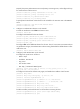
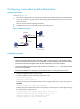
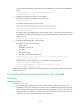
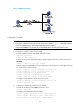
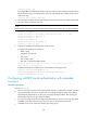
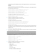
Figure 121 Network diagram
Configuration procedure
NOTE:
• For re-DHCP authentication, configure a public address pool (20.20.20.0/24, in this example) and a
private address pool (10.0.0.0/24, in this example) on the DHCP server. (Details not shown.)
• For re-DHCP authentication, the Firewall must be configured as a DHCP relay agent (instead of a DHCP
server) and the portal-enabled interface must be configured with a primary IP address (a public IP
address) and a secondary IP address (a private IP address). For information about DHCP relay a
g
ent
configuration, see
Network Management Configuration Guide
.
• Make sure that the IP address of the portal device added on the portal server is the public IP address of
the interface connecting users (20.20.20.1 in this example), the private IP address range for the IP
address group associated with the portal device is the private network segment where the users reside
(10.0.0.0/24 in this example), and the public IP address range for the IP address group is the public
network segment 20.20.20.0/24.
• Configure IP addresses for the Firewall and servers as shown in Figure 121
and make sure that the host,
Firewall, and servers can reach each other.
• Configure the RADIUS server properly to provide authentication/accounting functions for users.
1. Configure a RADIUS scheme on the Firewall.
# Create a RADIUS scheme named rs1 and enter its view.
<Firewall> system-view
[Firewall] radius scheme rs1
# Set the server type for the RADIUS scheme. When using the IMC server, set the server type to
extended.
[Firewall-radius-rs1] server-type extended
# Specify the primary authentication server and primary accounting server, and configure the keys
for communication with the servers.
[Firewall-radius-rs1] primary authentication 192.168.0.113
[Firewall-radius-rs1] primary accounting 192.168.0.113
[Firewall-radius-rs1] key authentication radius
[Firewall-radius-rs1] key accounting radius