HP High-End Firewalls Attack Protection Configuration Guide Part number: 5998-2650 Software version: F1000-A-EI&F1000-S-EI: R3721 F5000: F3210 F1000-E: F3171 Firewall module: F3171 Document version: 6PW101-20120719
Legal and notice information © Copyright 2012 Hewlett-Packard Development Company, L.P. No part of this documentation may be reproduced or transmitted in any form or by any means without prior written consent of Hewlett-Packard Development Company, L.P. The information contained herein is subject to change without notice.
Contents Configuring blacklist ···················································································································································· 1 Overview············································································································································································ 1 Recommended configuration procedure················································································································
Displaying information about protected IP address entries ·············································································· 34 TCP proxy configuration example ································································································································ 35 Configuration guidelines ··············································································································································· 37 Configuring IDS collaboration ·····
Configuring an SMTP filtering policy ·················································································································· 68 Configuring a POP3 filtering policy ···················································································································· 69 Configuring an FTP filtering policy ······················································································································ 71 Configuring a telnet filtering policy ·····
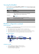
Configuring blacklist NOTE: The blacklist configuration is available only in the web interface. Overview Blacklist is an attack prevention mechanism that filters packets based on source IP address. Compared with ACL-based packet filtering, the blacklist feature is easier to configure and fast in filtering packets sourced from particular IP addresses. The firewall can dynamically add and remove blacklist entries. This is implemented in cooperation with the scanning detection feature.
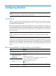
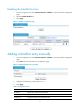
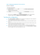
Enabling the blacklist function 1. From the navigation tree, select Intrusion Detection > Blacklist to enter the blacklist management page. 2. Select the Enable Blacklist box. 3. Click Apply. Figure 1 Blacklist management page Adding a blacklist entry manually 1. From the navigation tree, select Intrusion Detection > Blacklist to enter the blacklist management page. 2. Click Add to enter the blacklist entry configuration page. Figure 2 Adding a blacklist entry manually 3.
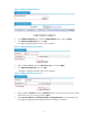
Viewing the blacklist From the navigation tree, select Intrusion Detection > Blacklist to enter the blacklist management page, where you can view the blacklist information, as shown in Figure 1. Table 2 describes the blacklist fields. Table 2 Field description Field Description IP Address Blacklisted IP address Type of the blacklist entry. Possible values include: • Auto—Added by the scanning detection feature automatically. • Manual—Added manually or modified manually.
Figure 4 Enabling the blacklist feature 3. In the Global Configuration area, select the Enable Blacklist option, and click Apply. 4. In the Blacklist Configuration area, click Add. The page for adding a blacklist entry for Host D appears. Figure 5 Adding a blacklist entry for Host D 5. Enter IP address 5.5.5.5, select the Permanence option., and click Apply 6. In the Blacklist Configuration area, click Add. The page for adding a blacklist entry for Host C appears.
Figure 7 Configuring scanning detection for the untrusted zone 9. Select security zone Untrust, select the Enable Scanning Detection option, set the scanning threshold to 4500, select the Add the source IP to the blacklist option, and Click. Verifying the configuration • Select Intrusion Detection > Blacklist from the navigation tree to display the list. Check whether the manually added blacklist entries appear on the blacklist.
Configuring packet inspection NOTE: The packet inspection configuration is available only in the web interface. Overview A single-packet attack, or malformed packet attack, occurs when either of the following events occurs: • An attacker sends defective IP packets, such as overlapping IP fragments and packets with illegal TCP flags, to a target system, making the target system malfunction or crash when processing such packets.
Attack type Description Tracert The Tracert program usually sends UDP packets with a large destination port number and an increasing TTL (starting from 1). The TTL of a packet is decreased by 1 when the packet passes each router. Upon receiving a packet with a TTL of 0, a router must send an ICMP time exceeded message back to the source IP address of the packet. A Tracert attacker exploits the Tracert program to figure out the network topology.
Item Description Discard Packets when the specified attack is detected Select this option to discard detected attack packets. Enable Fraggle Attack Detection Enable or disable detection of Fraggle attacks. Enable Land Attack Detection Enable or disable detection of Land attacks. Enable WinNuke Attack Detection Enable or disable detection of WinNuke attacks. Enable TCP Flag Attack Detection Enable or disable detection of TCP flag attacks.
Figure 10 Enabling Land and Smurf attack detection for the untrusted zone 3. Select Untrust from the Zone list, select Discard Packets when the specified attack is detected, select Enable Land Attack Detection, select Enable Smurf Attack Detection, click Apply. Verifying the configuration Check that Firewall can detect Land and Smurf attacks from the untrusted zone, output alarm logs accordingly, and drop the attack packets.
Configuring traffic abnormality detection NOTE: The traffic abnormality detection configuration is available only in the web interface. Overview The traffic abnormality detection feature analyzes the characteristics of traffic to detect abnormal traffic and take countermeasures accordingly. Supported countermeasures include outputting alarm logs, dropping packets, and blacklisting the source of the packets.
Connection limit When an internal user initiates a large number of connections to a host on the external network in a short period of time, system resources on the firewall will be used up soon. This will make the firewall unable to service other users. In addition, if an internal server receives large quantities of connection requests in a short period of time, the server will not be able to process normal connection requests from other hosts.
Figure 11 ICMP flood detection configuration page To configure ICMP flood detection, follow these steps: 1. In the Attack Prevention Policy area, specify the protection action to be taken upon detection of an ICMP flood attack. If you do not select the Discard packets when the specified attack is detected option, the firewall only collects ICMP flood attack statistics. 2.
Table 5 Configuration items Item Description IP Address Specify the IP address of the protected host. Set the protection action threshold for ICMP flood attacks that target the protected host. Action Threshold Protected Host Configuration If the sending rate of ICMP packets destined for the specified IP address constantly reaches or exceeds this threshold, the firewall enters the attack protection state and takes attack protection actions as configured.
Figure 13 UDP flood detection configuration page To configure UDP flood detection, follow these steps: 1. In the Attack Prevention Policy area, specify the protection action to be taken upon detection of a UDP flood attack. If you do not select the Discard packets when the specified attack is detected option, the firewall only collects UDP flood attack statistics. 2.
Item Description Set the silent threshold for actions that protect against UDP flood attacks targeting the protected host. Silent Threshold If the sending rate of UDP packets destined for the specified IP address drops below this threshold, the firewall returns to the attack detection state and stops the protection actions. Set the protection action threshold for UDP flood attacks that target a host in the protected security zone.
1. In the DNS Flood Attack Prevention Policy area, select Enable DNS Flood Attack Detection. The firewall will collect DNS flood attack statistics, and output logs upon detecting DNS flood attacks. 2. In the DNS Flood Configuration area, view the configured DNS flood detection rules, or click Add to enter the page shown in Figure 16 to configure a DNS flood detection rule. Table 7 describes the configuration items.
Figure 17 SYN flood detection configuration page To configure SYN flood detection, follow these steps: 1. In the Attack Prevention Policy area, specify the protection actions to be taken upon detection of a SYN flood attack. If you do not select any option, the firewall only collects SYN flood attack statistics. The available protection actions include: { { 2. Discard packets when the specified attack is detected.
Table 8 Configuration items Item Description IP Address Specify the IP address of the protected host. Set the protection action threshold for SYN flood attacks that target the protected host. Action Threshold Protected Host Configuration If the sending rate of SYN packets destined for the specified IP address constantly reaches or exceeds this threshold, the firewall enters the attack protection state and takes attack protection actions as configured.
Table 9 Configuration items Item Description Security Zone Select a security zone to perform connection limit configuration for it. Discard packets when the specified attack is detected Select this option to discard subsequent packets destined for or sourced from an IP address when the number of the connections for that IP address has exceeded the limit.
Item Description Select this option to allow the system to blacklist a suspicious source IP address. Add a source IP to the blacklist If this option is selected, you can then set the lifetime of the blacklisted source IP addresses. IMPORTANT: Only when the blacklist feature is enabled, can the scanning detection function blacklist a suspect and discard subsequent packets from the suspect. Lifetime Set the lifetime of the blacklist entry.
• Configure destination IP address-based connection limit for the DMZ, and set the number of connections the server can accommodate to, for example, 10000. • Configure SYN flood detection for the DMZ, and set the action threshold for attacks targeting the internal server (for example, to 5000 packets per second) and the silent threshold (for example, to 1000 packets per second). Set the attack protection action to blocking subsequent packets destined for the server.
• Select zone Untrust. • Select the Enable Scanning Detection option. • Set the scanning threshold to 4500 connections per second. • Select the Add the source IP to the blacklist option. • Click Apply. # Configure connection limits for the trusted zone. From the navigation tree, select Intrusion Detection > Traffic Abnormality > Connection Limit. The connection limit configuration page appears, as shown in Figure 24.
Figure 26 Configuring SYN flood detection for the DMZ Perform the following operations on the page: • Select zone DMZ. • In the Attack Prevention Policy area, select the Discard packets when the specified attack is detected option. • Click Apply. • In the SYN Flood Configuration area, click Add. The SYN flood attack detection page appears.
• If a host in zone Trust initiates 100 or more connections, Firewall should output alarm logs and discard subsequent connection request packets from the host. You can select Intrusion Detection > Statistics from the navigation tree to view how many times that a connection limit per source IP address has been exceeded and the number of packets dropped.
Configuring URPF NOTE: URPF configuration is available only in the web interface. URPF overview What is URPF Unicast Reverse Path Forwarding (URPF) protects a network against source address spoofing attacks. Attackers launch such attacks by sending a large number of packets with forged source addresses. For applications using IP-address-based authentication, this type of attacks allows unauthorized users to access the system in the name of authorized users, or even access the system as the administrator.
3. If the source address is not found in the FIB table, URPF makes a decision based on the default route and the allow-default-route option. { { 4. If the default route is available but the allow-default-route option is not selected, the packet is rejected no matter which check approach is taken. If the default route is available and the allow-default-route option is selected, URPF operates depending on the check approach.
Item Description Type of Check Set the URPF check type, Strict or Loose. URPF configuration example CAUTION: In this configuration example, either Device A or Device B is the firewall. Network requirements As shown in Figure 30, Device A directly connects to Device B. Enable strict URPF check in zoneB of Device B to allow packets whose source addresses match ACL 2010 to pass. Enable strict URPF check in zoneA of Device A to allow use of the default route for URPF check.
Figure 32 Configuring ACL 2010 • Select Permit in Operation. • Select Source IP Address and enter 10.1.1.0 in the field. • Enter 0.0.0.255 in Source Wildcard. • Click Apply. # Enable strict URPF check in zoneB. • Select Intrusion Detection > URPF Check from the navigation tree and perform the following operations, as shown in Figure 33. Figure 33 Configuring URPF in zoneB • Select zoneB in Security Zone. • Select Enable URPF. • Select ACL and enter 2010 in the field.
• Select Intrusion Detection > URPF Check from the navigation tree and perform the following operations, as shown in Figure 34. Figure 34 Configuring URPF on zoneA • Select zoneA in Security Zone. • Select Enable URPF. • Select Allow Default Route. • Select Strict in Type of Check. • Click Apply.
Configuring TCP proxy NOTE: The TCP proxy configuration is available only in the web interface. Overview SYN flood attack As a general rule, the establishment of a TCP connection is a three-way handshake: 1. The request originator sends a SYN message to the target server. 2. After receiving the SYN message, the target server establishes a TCP connection in the SYN_RECEIVED state, returns a SYN ACK message to the originator, and waits for a response. 3.
Figure 35 Network diagram for unidirectional proxy Figure 36 Network diagram for unidirectional/bidirectional proxy How TCP proxy working mechanism Unidirectional proxy Figure 37 Data exchange process in unidirectional proxy mode After receiving a SYN message from a client to the protected server (such a message matches a protected IP address entry), the TCP proxy sends back a SYN ACK message with a wrong sequence number on behalf of the server, that is, using the IP address and port number of the server
Bidirectional proxy Figure 38 Data exchange process in bidirectional proxy mode After receiving a SYN message from a client to the protected server (such a message matches a protected IP address entry), the TCP proxy sends back a SYN ACK message with the window size being 0 on behalf of the server. If the client is legitimate, the TCP proxy will receive an ACK message, and then sets up a connection between itself and the server through a three-way handshake on behalf of the client.
Performing global TCP proxy setting Select Intrusion Detection > TCP Proxy > TCP Proxy Configuration from the navigation tree to enter the page shown in Figure 39. The Global Configuration area allows you to perform global setting for TCP proxy. Figure 39 TCP proxy configuration Table 12 Configuration items Item Description Unidirection/Bidirediction Set the global proxy mode of TCP proxy.
Figure 40 Protected IP address entries Figure 41 Protected IP address entry configuration page Table 13 Configuration items Item Description Protected IP Address Enter the IP address to be protected by the TCP proxy. It is the destination IP address of the TCP connection. Enter the destination port of the TCP connection. Port Number The option any specifies that TCP proxy services TCP connection requests to any port of the server at the destination IP address.
TCP proxy configuration example Network requirements As shown in Figure 42, configure bidirectional TCP proxy on Firewall to protect Server A, Server B, and Server C against SYN flood attacks. Add a protected IP address entry for Server A and configure dynamic TCP proxy for the other servers. Figure 42 Network diagram Configuration procedure # Assign IP addresses for the interfaces and then add interface GigabitEthernet 1/1 to zone Untrust, and GigabitEthernet 1/2 to zone Trust. (Details not shown.
Figure 44 Add an IP address entry for protection • Enter 20.0.0.10 in the Protected IP Address field. • Click Apply. # Configure the SYN flood detection feature, specifying to automatically add protected IP address entries. • Select Intrusion Detection > Traffic Abnormality > SYN Flood from the navigation tree. In the Attack Prevention Policy area, configure the action to be taken upon detecting a SYN flood attack, as shown in Figure 45.
Figure 46 Configuring global settings • Select Global Configuration of Security Zone. • Click Apply. Configuration guidelines Follow these guidelines when you configure TCP proxy: 1. TCP proxy is effective only for incoming traffic of the security zone. 2. The performance of the Web-based management system may be degraded if the system's IP address and port number are in the protected IP entry list.
Configuring IDS collaboration Feature and hardware compatibility Feature F1000-A-EI/S-EI F1000-E F5000 Firewall module IDS collaboration Yes Yes Yes No NOTE: • The firewall device can collaborate with only Venusense IDS devices. • The IDS collaboration configuration is available only in the web interface. Overview IDS collaboration is introduced for firewalls to work with an Intrusion detection system (IDS) device. As shown in Figure 47, the collaboration process occurs: 1.
Configuration guidelines When you configure IDS collaboration, follow these guidelines: • Both the firewall devices and IDS devices must support and have SNMPv2c configured. • The aging time for an IDS blocking entry is five minutes. The timer restarts if the firewall receives an SNMP trap with the same attack information before the timer expires. • A blocking entry is effective only to subsequent connections matching this entry.
Displaying intrusion detection statistics NOTE: The intrusion detection configuration is available only in the web interface. Overview Intrusion detection is an important network security feature. By analyzing the contents and behaviors of packets passing by, it can determine whether the packets are attack packets and take actions accordingly as configured. Supported actions include outputting alarm logs, discarding packets, and adding the attacker to the blacklist.
Figure 49 Intrusion detection statistics Table 15 Field description Field Description Fraggle A Fraggle attack occurs when an attacker sends large amounts of UDP echo requests with the UDP port number being 7 or Chargen packets with the UDP port number being 19, resulting in a large quantity of junk replies and finally exhausting the bandwidth of the target network.
Field Description Scan A scanning attack probes the addresses and ports on a network to identify the hosts attached to the network and application ports available on the hosts and to figure out the topology of the network, so as to get ready further attacks. Source Route A source route attack exploits the source route option in the IP header to probe the topology of a network. Smurf A Smurf attacker sends large quantities of ICMP echo requests to the broadcast address of the target network.
Configuring ARP attack protection The Address Resolution Protocol (ARP) is easy to use, but it is often exploited by attackers because of its lack of security mechanism. • ARP packets by acting as a trusted user or gateway so that the receiving devices obtain incorrect ARP entries. • A large number of IP packets with unreachable destinations. As a result, the receiving device continuously resolves destination IP addresses and thus its CPU is overloaded.
interface regularly. In this way, the hosts on the network segment can learn the correct gateway address information and can therefore access the network. 2. Prevent aging of the gateway ARP entry In practice, if the network load is heavy or the CPU usage of hosts on the network is high, ARP packets may be dropped or the hosts cannot process ARP packets timely.
Figure 50 Configuring periodic sending of gratuitous ARP packets Table 16 Configuration items Item Description Specify an interface and interval for periodically sending gratuitous ARP packets. Select an interface from the Standby Interface list, set its sending interval, and then click << to add it to the Sending Interface list box. To delete the combination of an interface and its sending interval, select it from the Sending Interface list and click >>.
• If you change the interval for sending gratuitous ARP packets, the configuration is effective at the next sending interval. • The frequency of sending gratuitous ARP packets may be much lower than is expected if this function is enabled on multiple interfaces, if each interface is configured with multiple secondary IP addresses, or if a small sending interval is configured in such cases. Configuration procedure To configure gratuitous ARP: Step Command Remarks 1. Enter system view.
Configuring ARP automatic scanning in the web interface NOTE: • Do not perform other operations when ARP automatic scanning is in progress. • ARP automatic scanning may take a long time. You can abort the scanning by clicking Interrupt on the ARP scan page. Select Firewall > ARP Anti-Attack > Scan from the navigation tree to enter the ARP scanning configuration page, as shown in Figure 51.
Item Description Also scan IP addresses of dynamic ARP entries Set whether to scan the IP addresses of the existing dynamic ARP entries. After the above configuration, click Scan to begin ARP automatic scanning. To abort scanning, click Interrupt. Configuring fixed ARP in the web interface NOTE: • The static ARP entries resulting from conversion are the same with those manually configured.
Configuring ARP automatic scanning and fixed ARP at the CLI Configuration guidelines Follow these guidelines when you configure ARP automatic scanning and fixed ARP: • IP addresses existing in ARP entries are not scanned. • ARP automatic scanning may take some time. To stop an ongoing scan, press Ctrl + C. Dynamic ARP entries are created based on ARP replies received before the scan is terminated.
Configuring TCP attack protection Overview An attacker can attack the device during the process of TCP connection establishment. To prevent such attacks, the device provides the following features: • SYN Cookie • Protection against Naptha attacks This document describes the attacks these features can prevent, working mechanisms of these features, and configuration procedures.
Enabling protection against Naptha attacks Naptha attacks are similar to the SYN Flood attacks. Attackers can perform Naptha attacks by using the six TCP connection states (CLOSING, ESTABLISHED, FIN_WAIT_1, FIN_WAIT_2, LAST_ACK, and SYN_RECEIVED), and SYN Flood attacks by using only the SYN_RECEIVED state.
Configuring firewall NOTE: The firewall configuration is available only at the CLI. Overview A firewall can block unauthorized accesses from the Internet to a protected network while allowing internal network users to access the Internet through, for example, WWW, or to send/receive E-mails. A firewall can also be used to control access to the Internet, for example, to permit only specific hosts within the organization to access the Internet.
Enabling the IPv6 firewall function Following these steps to enable the IPv6 firewall function: Step Command Remarks 1. Enter system view. system-view N/A 2. Enable the IPv6 firewall function. firewall ipv6 enable Disabled by default. Configuring the default filtering action of the IPv6 firewall The default filtering action configuration is used for the firewall to determine whether to permit a data packet to pass or deny the packet when there is no appropriate criterion for judgment.
To configure IPv6 packet filtering on an interface: Step Command Remarks 1. Enter system view. system-view N/A 2. Enter interface view. interface interface-type interface-number N/A 3. Configure IPv6 packet filtering on an interface. firewall packet-filter ipv6 { acl6-number | name acl6-name } { inbound | outbound } IPv6 packets are not filtered by default. Displaying and maintaining a packet filtering firewall Step Command Remarks 1.
Configuring content filtering NOTE: The content filtering configuration is available only in the Web interface.
• ActiveX blocking—Blocks ActiveX plugin requests to untrusted websites, protecting networks from being attacked by malicious ActiveX plugins. • Java applet blocking—Blocks Java applet requests to untrusted websites, protecting networks from being attacked by malicious Java applets.
NOTE: FTP command words refer to the command words carried in the FTP requests, including RETR, STOR, APPE, USER, PASS, PORT, PASV, RNFR, RNTO, DELE, LIST, and QUIT, rather than the command words typed in the command line. For example, to upload a file named 123.txt, you type command put 123.txt. In this case, the FTP command word to be filtered is not put but STOR.
Task Description Configuring URL hostname filtering entries Used for URL hostname filtering in HTTP filtering policies. By default, no URL hostname filtering entries exist. Filename filtering entries include: • SMTP filename filtering entries—For attachment name filtering in SMTP filtering policies. Configuring filename filtering entries • POP3 filename filtering entries—For attachment name filtering in POP3 filtering policies.
Table 20 Content filtering policy template configuration task Task Description By default, no HTTP filtering policy templates exist. IMPORTANT: Configuring a content filtering policy template 4. You can configure a content filtering policy template in the content filtering module or in the interzone policy module. The configuration items in the two modules are the same. This document describes the policy template configuration in the content filtering module.
Figure 53 Keyword filtering entry list Figure 54 Adding a keyword filtering entry Table 23 Configuration items Item Description Name Specify the name of the keyword filtering entry. Specify the keywords for the keyword filtering entry. Keyword You can specify up to 16 keywords separated by commas. You can use a wildcard (*) to represent any string up to 6 characters. The Wildcard (*) can appear only once in each keyword and cannot be at the start or end of a keyword.
Configuring URL hostname filtering entries Select Identification > Content Filtering > Filtering Entry from the navigation tree, and then click the URL Hostname tab to enter the URL hostname filtering entry list page, as shown in Figure 55. Then, click Add to enter the page for adding a URL hostname filtering entry, as shown in Figure 56.
Figure 57 Filename filtering entry list Figure 58 Adding a filename filtering entry Table 25 Configuration items Item Description Name Specify the name of the filename filtering entry. Specify filename keywords for the filename filtering entry. You can specify up to 16 filename keywords separated by commas. • If you specify a filename keyword in the format of filename.extension, the firewall will Filename perform exact match for this keyword.
Configuring email address filtering entries Select Identification > Content Filtering > Filtering Entry from the navigation tree, and then click the Email Address tab to enter the email address filtering entry list page, as shown in Figure 59. Then, click Add to enter the page for adding an email address filtering entry, as shown in Figure 60.
Figure 61 URL parameter filtering keyword setup Figure 62 Adding a URL parameter filtering keyword Table 27 Configuration item Item Description Specify a URL parameter filtering keyword. See Figure 62 for the requirements on a keyword. Keyword See "Configuration guidelines" for the rules of using wildcards. IMPORTANT: A keyword string can contain spaces. However, consecutive spaces are not allowed.
Figure 63 Java blocking keywords setup Figure 64 Adding a Java blocking keyword Table 28 Configuration item Item Keyword Description Specify a suffix keyword for Java blocking. See Figure 64 for the requirements on a keyword. Configuring ActiveX blocking keywords Select Identification > Content Filtering > Filtering Entry from the navigation tree, and then click the ActiveX tab to enter the ActiveX blocking keyword list page, as shown in Figure 65.
Figure 66 Adding an ActiveX blocking keyword Table 29 Configuration item Item Keyword Description Specify a suffix keyword for ActiveX blocking. See Figure 66 for the requirements on a keyword. Configuring an HTTP filtering policy Select Identification > Content Filtering > Filtering Policy from the navigation tree. The HTTP filtering policy list page appears, as shown in Figure 67. Then, click Add to enter the page for adding an HTTP filtering policy, as shown in Figure 68.
Figure 68 Adding an HTTP filtering policy Table 30 Configuration items Item Description Name Specify the name for the HTTP filtering policy. URL Filtering Select the filtering entries to be used for URL hostname filtering. Available filtering entries are the configured URL hostname filtering entries. Select the filtering entries to be used for header filtering. Header Filtering Available filtering entries are the configured HTTP keyword filtering entries.
Item Description Specify whether to log packet matching events. IMPORTANT: Enable Logging The logging function takes effect only when it is enabled in both the content filtering policy and the interzone policy. Configuring an SMTP filtering policy Select Identification > Content Filtering > Filtering Policy from the navigation tree, and then click the SMTP Policy tab to enter the SMTP filtering policy list page, as shown in Figure 69.
Item Description Select the filtering entries to be used for sender filtering. Sender Filtering Available filtering entries are the configured email address filtering entries. Receiver Filtering Subject Filtering Select the filtering entries to be used for receiver filtering. Available filtering entries are the configured email address filtering entries. Select the filtering entries to be used for subject filtering. Available filtering entries are the configured SMTP keyword filtering entries.
Figure 71 POP3 filtering policy list Figure 72 Adding a POP3 filtering policy Table 32 Configuration items Item Description Name Specify the name for the POP3 filtering policy. Sender Filtering Receiver Filtering Subject Filtering Select the filtering entries to be used for sender filtering. Available filtering entries are the configured email address filtering entries. Select the filtering entries to be used for receiver filtering.
Item Description Select the filtering entries to be used for body filtering. Body Filtering Available filtering entries are the configured POP3 keyword filtering entries. Attachment Name Filtering Attachment Filtering Attachment Content Filtering Select the filtering entries to be used for attachment name filtering. Available filtering entries are the configured filename filtering entries. Select the filtering entries to be used for attachment content filtering.
Figure 74 Adding an FTP filtering policy Table 33 Configuration items Item Description Name Specify the name for the FTP filtering policy. Command Filtering Upload Filename Filtering Download Filename Filtering Select the filtering entries to be used for command word filtering. Available filtering entries are the configured FTP keyword filtering entries. Select the filtering entries to be used for upload filename filtering.
Figure 75 Telnet filtering policy list Figure 76 Adding a Telnet filtering policy Table 34 Configuration items Item Description Name Specify the name for the Telnet filtering policy. Select the filtering entries to be used for command word filtering. Available filtering entries are the configured Telnet keyword filtering entries. Command Filtering IMPORTANT: • Packets that match these filtering conditions will be dropped.
Figure 77 Policy template list Figure 78 Adding a content filtering policy template Table 35 Configuration items Item Description Name Enter the name of the content filtering policy template. HTTP Filtering Policy Select the HTTP filtering policy to be used in the content filtering policy template. SMTP Filtering Policy Select the SMTP filtering policy to be used in the content filtering policy template.
Figure 79 Statistic information Content filtering configuration example Network requirements As shown in Figure 80, hosts in LAN segment 192.168.1.0/24 access the Internet through Firewall. Security zones Trust and Untrust are configured on Firewall for the LAN and the Internet respectively. Perform the following configurations on Firewall: • Enable HTTP body filtering to block HTTP responses that carry keyword abc.
Figure 80 Network diagram Configuration procedures 1. Configure IP addresses for the interfaces of the Firewall and assign the interfaces to security zones. (Details not shown.) 2. Configure filtering entries. # Configure an HTTP keyword filtering entry named abc. { Select Identification > Content Filtering > Filtering Entry from the navigation tree. The keyword filtering entry list page appears. Click Add and then configure the following configurations, as shown in Figure 81.
Figure 82 Configuring Telnet keyword filtering entry reboot { Enter the entry name reboot_telnet. { Enter the keyword reboot. { Select protocol Telnet. { Click Apply. # Configure an SMTP filename filtering entry .exe. { Click the Filename tab, and then click Add to perform the configurations shown in Figure 83. Figure 83 Configuring an SMTP filename filtering entry .exe { Enter the entry name exe_smtp. { Enter the filename keyword *.exe. { Select protocol SMTP. { Click Apply.
Figure 84 Configuring an FTP filename filtering entry abc 3. { Enter the entry name abc_ftp. { Enter the filename keyword abc. { Select protocol FTP. { Click Apply. Configuring content filtering policies: # Configure an HTTP filtering policy without Java applet blocking. { Select Identification > Content Filtering > Filtering Policy from the navigation tree. The HTTP filtering policy list page appears. Then, click Add to perform the configurations shown in Figure 85.
Figure 85 Configuring an HTTP filtering policy without Java applet blocking { Enter the policy name http_policy1. { Click the expansion button before Body Filtering. { { Select body filtering entry abc_http in the available filtering entry list, and then click << to add it to the selected filtering entry list. Click Apply. # Configure an HTTP filtering policy with Java applet blocking. { On the HTTP filtering policy list page, click Add to perform the configurations shown in Figure 86.
Figure 86 Configuring an HTTP filtering policy with Java applet blocking { Enter the policy name http_policy2. { Click the expansion button before Body Filtering. { Select body filtering entry abc_http in the available filtering entry list, and then click << to add it to the selected filtering entry list. { Select the Java Applet Blocking box. { Click Apply. # Configure an SMTP filtering policy. { Click the SMTP Policy tab, and then click Add to perform the configurations shown in Figure 87.
Figure 87 Configuring an SMTP filtering policy { Enter the policy name smtp_policy. { Click the expansion button before Attachment Filtering. { { In the Attachment Name Filtering area, select filename filtering entry exe_smtp in the available filtering entry list, and then click << to add it to the selected filtering entry list. Click Apply.
# Configure an FTP filtering policy. { Click the FTP Policy tab, and then click Add to perform the configurations shown in Figure 88. Figure 88 Configuring an FTP filtering policy { Enter the policy name ftp_policy. { Click the expansion button before Upload Filename Filtering. { { Select filename filtering entry abc_ftp in the available filtering entry list, and then click << to add it to the selected filtering entry list. Click Apply. # Configure a Telnet filtering policy.
Figure 89 Configuring a Telnet filtering policy { Enter the policy name telnet_policy. { Click the expansion button before Command Filtering. { { 4. Select command filtering entry reboot_telnet in the available filtering entry list, and then click << to add it to the selected filtering entry list. Click Apply. Configure content filtering policy templates: # Configure a content filtering policy template without Java applet blocking.
{ Select HTTP filtering policy http_policy1. { Select SMTP filtering policy smtp_policy. { Select FTP filtering policy ftp_policy. { Select Telnet filtering policy telnet_policy. { Click Apply. # Configure a content filtering policy template with Java applet blocking. { Select Identification > Content Filtering > Policy Template from the navigation tree, and then click Add to perform the configurations shown in Figure 91.
Figure 92 Configuring the interzone policy referencing the template without Java applet blocking { Select Trust as the source zone. { Select Untrust as the destination zone. { Select any_address as the source IP address. { In the Destination IP Address area, select the New IP Address option and then enter destination IP address 5.5.5.5/0.0.0.0. { Select any_service as the service name. { Select Permit as the filter action. { Select the Enable the rule box to enable the rule.
Figure 93 Configuring the interzone policy referencing the template with Java applet blocking { Select any_address as the source IP address and destination IP address. { Select any_service as the service name. { Select Permit as the filter action. { Select content filtering policy template template2. { Select the Enable the rule box to enable the rule. { Click Apply.
Figure 94 Content filtering statistics Configuration guidelines 1. Wildcard usage in URL hostname filtering keywords: { { { { The caret (^) matches the beginning of the string. It can be used only once in a keyword and must be at the beginning. The dollar sign ($) matches the end of the string. It can be used only once in a keyword and must be at the end. The ampersand sign (&) matches a single character other than dot (.) and space.
{ { { { 2. A keyword with ^ at the beginning or $ at the end indicates an exact match. For example, keyword ^webfilter matches website addresses starting with webfilter (such as webfilter.com.cn) or containing webfilter at the beginning of a string after a dot (such as cmm.webfilter-any.com). Keyword ^webfilter$ matches website addresses containing standalone word webfilter like www.webfilter.com; it does not match website addresses like www.webfilter-china.com.
Support and other resources Contacting HP For worldwide technical support information, see the HP support website: http://www.hp.
Conventions This section describes the conventions used in this documentation set. Command conventions Convention Description Boldface Bold text represents commands and keywords that you enter literally as shown. Italic Italic text represents arguments that you replace with actual values. [] Square brackets enclose syntax choices (keywords or arguments) that are optional. { x | y | ... } Braces enclose a set of required syntax choices separated by vertical bars, from which you select one.
Network topology icons Represents a generic network device, such as a router, switch, or firewall. Represents a routing-capable device, such as a router or Layer 3 switch. Represents a generic switch, such as a Layer 2 or Layer 3 switch, or a router that supports Layer 2 forwarding and other Layer 2 features. Represents a firewall. Port numbering in examples The port numbers in this document are for illustration only and might be unavailable on your device.
Index ABCDEFOPRTUV A Enabling the SYN Cookie feature,50 Adding a blacklist entry manually,2 F B Feature and hardware compatibility,38 Blacklist configuration example,3 O C Overview,1 Overview,55 Configuration guidelines,87 Overview,6 Configuration guidelines,39 Overview,10 Configuration guidelines,37 Overview,30 Configuration procedure,26 Overview,50 Configuration procedure,40 Overview,40 Configuration procedure,7 Overview,38 Configuring a packet-filter firewall,52 Overview,52 Config