HP High-End Firewalls Getting Started Guide Part number: 5998-2646 Software version: F1000-A-EI&F1000-S-EI: R3721 F5000: F3210 F1000-E: F3171 Firewall module: F3171 Document version: 6PW101-20120719
Legal and notice information © Copyright 2012 Hewlett-Packard Development Company, L.P. No part of this documentation may be reproduced or transmitted in any form or by any means without prior written consent of Hewlett-Packard Development Company, L.P. The information contained herein is subject to change without notice.
Contents Overview ······································································································································································ 1 Product overview ······························································································································································· 1 F1000-S-EI/F1000-A-EI ····························································································································
Web login example ······················································································································································· 39 HTTP login example ·············································································································································· 39 HTTPS login example ············································································································································ 40 Troublesho
Configuring the port status detection timer·················································································································· 82 Setting the temperature thresholds for a card ············································································································· 82 Monitoring an NMS-connected interface ···················································································································· 82 Clearing unused 16-bit interface i
Documents ···························································································································································· 116 Websites······························································································································································· 116 Conventions ·····························································································································································
Overview This documentation is applicable to the following firewall products: • HP F1000-S-EI VPN firewall (hereinafter referred to as the F1000-S-EI) • HP F1000-A-EI VPN firewall (hereinafter referred to as the F1000-A-EI) • HP F1000-E VPN firewall (hereinafter referred to as the F1000-E) • HP F5000 VPN firewall (hereinafter referred to as the F5000) • HP firewall module You can configure most of the firewall functions in the web interface and some functions at the command line interface (CLI).
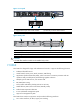
Figure 1 Front panel (1) Copper Ethernet port of the combo interface (2) Fiber SFP port of the combo interface (3) Console port (4) USB interface Figure 2 Rear panel (1) Power supply slot 1 (PWR1) (2) Power supply slot 2 (PWR2) (3) Interface module slot 2 (SLOT2) (4) ”OPEN BOOK” mark (5) Grounding screw and mark (6) Interface module slot 1 (SLOT1) CAUTION: A 2*10GE fiber interface module can be installed only in slot 1. F1000-E The F1000-E is designed for large- and medium-sized networks.
Two high-speed interface module (HIM) expansion slots, which support the following interface modules: 4GBE, 8GBE, HIM-1EXP, and 4GBP. • Figure 3 Front panel (1) AC-input power receptacle (100 VAC to 240 VAC, 50 or 60 Hz at 2.
• Protection against external attacks, internal network protection, traffic monitoring, email filtering, web filtering, application layer filtering • ASPF • Multiple types of VPN services, such as L2TP VPN, GRE VPN, IPsec VPN, and dynamic VPN • RIP/OSPF/BGP routing, routing policy, and policy-based routing • Power module 1+1 redundancy backup (AC+AC or DC+DC) • Multiple types of service interface cards • High availability functions, such as stateful failover and VRRP Figure 5 Front panel 1 7
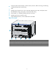
Figure 6 Rear panel (1) Rear cover handle (do not use this handle to lift the chassis) (2) Air filter (optional) (3) Chassis handle (4) Grounding terminal and sign (5) Air vents Firewall modules The HP Firewall modules are developed based on the Open Application Architecture (OAA) for carrier-level customers. A firewall module can be installed in the 5800/7500E/9500E/12500 Switch Series or an 6608/8800 router.
Figure 7 Firewall module for 5800 series switches Figure 8 Firewall module for 7500E/9500E/12500 series switches Figure 9 Firewall module for 6600/8800 routers Application scenarios F1000-S-EI/F1000-A-EI applications Firewall application With powerful filtering and management functions, the F1000-S-EI/F1000-A-EI can be deployed at the egress of an internal network to defend against external attacks and control internal access by separating security zones.
Figure 10 Network diagram Virtual firewall application The F1000-S-EI/F1000-A-EI supports the virtual firewall function. You can create multiple virtual firewalls on one firewall. Each virtual firewall can have its own security policy and can be managed independently.
VPN application The F1000-S-EI/F1000-A-EI supports VPN functions, helping branch offices and remote users securely access the resources in the headquarters and those in their own networks.
Figure 13 Network diagram F5000 application Large data centers are connected to the 10G core network usually through a 10G Ethernet. The F5000 firewall has a 10G processing capability and abundant port features. It can be deployed at the egress of a network to protect security for the internal network. You can deploy two firewalls to implement stateful failover. • Active-active stateful failover can balance user data. • Active-standby stateful failover improves availability of the firewalls.
Figure 14 Network diagram Firewall module application Firewall modules work with the main network devices (such as 5800/7500E/9500E/12500 switches and 6600/8800 routers). Deployed at the egress of a network, the firewall modules can protect against external attacks and implement security access control of the internal network by using security zones. You can meet the development of the network simply by installing more firewall modules to a switch or router.
Figure 15 Network diagram Quidview CAMS XLOG Network Management Zone Firewall Module Internet LAN Firewall Module DMZ Zone Mail Web DNS 11
Login overview Feature and hardware compatibility Feature F1000-A-EI/S-EI F1000-E F5000 Firewall module FIPS No No No Yes Login methods at a glance Login method Default state Logging in to the CLI: Logging in through the console port By default, login through the console port is enabled, no username or password is required, and the user privilege level is 3. Logging in through telnet By default, you can log in to a device through Telnet with the IP address 192.168.0.
CLI user interfaces The device uses user interfaces (also called "lines") to control CLI logins and monitor CLI sessions. You can configure access control settings, including authentication, user privilege, and login redirect on user interfaces. After users are logged in, their actions must be compliant with the settings on the user interfaces assigned to them. Users are assigned different user interfaces, depending on their login methods, as shown in Table 1.
Logging in to the CLI By default, the first time you access the CLI you must log in through the console port. At the CLI, you can configure Telnet or SSH for remote access. Logging in through the console port To log in through the console port, make sure the console terminal has a terminal emulation program (for example, HyperTerminal in Windows XP). In addition, the port settings of the terminal emulation program must be the same as the default settings of the console port in Table 2.
3. Select a serial port to be connected to the device, and set terminal parameters as follows: set Bits per second to 9600, Data bits to 8, Parity to None, Stop bits to 1, and Flow control to None, as shown in Figure 17 through Figure 19. NOTE: On Windows 2003 Server operating system, add the HyperTerminal program first, and then log in to and manage the device as described in this document.
Figure 19 Setting the properties of the serial port 4. Power on the device and press Enter if the device successfully completes the power-on self test (POST). A prompt such as appears after you press Enter. 5. Execute commands to configure the device or check the running status of the device. 6. To get help, enter ?. Configuring console login control settings The following authentication modes are available for controlling console logins: • None—Requires no authentication.
Table 3 Configuration required for different console login authentication modes Authentication mode Configuration tasks Reference None Set the authentication mode to none for the console user interface. "Configuring none authentication for console login." Password Enable password authentication on the console user interface. Set a password. "Configuring password authentication for console login." Enable scheme authentication on the console user interface.
Step Command Remarks user-interface console first-number [ last-number ] N/A 2. Enter console user interface view 3. Configure the authentication mode as local password authentication authentication-mode password By default, you can log in to the device through the console port without authentication and have user privilege level 3 after login. 4. Set the local password set authentication password { cipher | simple } password By default, no local password is set. 5.
Step Command Remarks Optional. By default, command accounting is disabled. The accounting server does not record the commands executed by users. 5. Enable command accounting. command accounting 6. Return to system view. quit N/A a. Enter ISP domain view: domain domain-name 7. Apply an AAA authentication scheme to the intended domain. b.
When users adopt the scheme mode to log in to the device, the level of the commands that the users can access depends on the user privilege level defined in the AAA scheme. • When the AAA scheme is local, the user privilege level is defined by the authorization-attribute level level command. • When the AAA scheme is RADIUS or HWTACACS, the user privilege level is configured on the RADIUS or HWTACACS server. • For more information about AAA, RADIUS, and HWTACACS, see Access Control Configuration Guide.
Step Command Remarks Optional. By default, the data bits of the console port is 8. 7. Configure the data bits. databits { 5 | 6 | 7 | 8 } 8. Define a shortcut key for enabling a terminal session. activation-key character 9. Define a shortcut key for terminating tasks. Data bits is the number of bits representing one character. The setting depends on the contexts to be transmitted.
Step Command Remarks Optional. 14. Set the idle-timeout timer. idle-timeout minutes [ seconds ] The default idle-timeout is 10 minutes. The system automatically terminates the user's connection if there is no information interaction between the device and the user within the idle-timeout time. Setting idle-timeout to 0 disables the timer.
To control Telnet access to the device working as a Telnet server, configure login authentication and user privilege levels for Telnet users. By default, password authentication applies to Telnet login, but no login password is configured. To allow Telnet access to the device after you enable the Telnet server, you must configure a password. The following are authentication modes available for controlling Telnet logins: • None—Requires no authentication and is insecure.
Step Command Remarks 4. Specify the none authentication mode. authentication-mode none By default, authentication mode for VTY user interfaces is password. 5. Configure the command level for login users on the current user interfaces. user privilege level level By default, the default command level is 0 for VTY user interfaces. Configure common settings for VTY user interfaces. See "Configuring common VTY user interface settings (optional)." Optional. 6.
Step 4. Specify the scheme authentication mode. Command Remarks authentication-mode scheme Whether local, RADIUS, or HWTACACS authentication is adopted depends on the configured AAA scheme. By default, local authentication is adopted. Optional. By default, command authorization is not enabled. 5. Enable command authorization. command authorization Create a HWTACACS scheme, and specify the IP address of the authorization server and other authorization parameters.
Step Command Remarks Optional. 8. Apply an AAA authentication scheme to the intended domain. a. Enter ISP domain view: domain domain-name By default, local authentication is used. b. Apply an AAA scheme to the domain: authentication default { hwtacacs-scheme hwtacacs-scheme-name [ local ] | local | none | radius-scheme radius-scheme-name [ local ] } For local authentication, configure local user accounts. c. Exit to system view: quit 9. Create a local user and enter local user view.
Step Command Remarks N/A 1. Enter system view. system-view 2. Enable display of copyright information. copyright-info enable 3. Enter one or multiple VTY user interface views. user-interface vty first-number [ last-number ] 4. Enable the terminal service shell 5. Enable the current user interface(s) to support either Telnet, SSH, or both of them protocol inbound { all | ssh | telnet } 6. Define a shortcut key for terminating tasks escape-key { default | character } 7.
Step Command Remarks Optional. By default, command auto-execution is disabled. 11. Specify a command to be automatically executed when a user logs in to the current user interface auto-execute command command The system automatically executes the specified command when a user logs in to the user interface, and ends the user connection after the command is executed. If the command triggers another task, the system does not end the user connection until the task is completed.
Step Command Remarks • Log in to an IPv4 Telnet server: 4. Use the device to log in to a Telnet server. telnet remote-host [ service-port ] [ [ vpn-instance vpn-instance-name ] | [ source { interface interface-type interface-number | ip ip-address } ] ] • Log in to an IPv6 Telnet server: Use either command.
Configuring the SSH server on the device Follow these guidelines when you configure the SSH server: • To make the command authorization or command accounting function take effect, apply an HWTACACS scheme to the intended ISP domain. This scheme must specify the IP address of the authorization server and other authorization parameters. For more information, see Access Control Configuration Guide.
Step Command Remarks Optional. By default, command authorization is not enabled. 8. Enable command authorization. command authorization By default, command level for a login user depends on the user privilege level. The user is authorized the command with the default level not higher than the user privilege level. With the command authorization configured, the command level for a login user is determined by both the user privilege level and AAA authorization.
Step Command a. Enter the default ISP domain view: domain domain-name b. Apply the specified AAA scheme to the domain: authentication default.{ hwtacacs-schem e hwtacacs-scheme-name [ local ] | local | none | radius-scheme radius-scheme-name [ local ] } 11. Configure the authentication mode. c. Exit to system view: quit Remarks Optional. For local authentication, configure local user accounts.
Task Command Remarks Log in to an IPv6 SSH server. ssh2 ipv6 server server is the IPv6 address or host name of the server. To work with the SSH server, you might need to configure the SSH client. For information about configuring the SSH client, see System Management and Maintenance Configuration Guide. Displaying and maintaining CLI login Task Command Remarks Display information about the user interfaces that are being used.
Logging in to the Web interface The device provides the web-based network management function to facilitate device operation and maintenance. With this function, you can visually manage and maintain network devices through the web interface. Feature and hardware compatibility Feature F1000-A-EI/S-EI F1000-E F5000 Firewall module FIPS No No No Yes The firewall does not support HTTP in FIPS mode.
3. Configure routes to make sure the PC and device can communicate with each other properly. 4. Open the browser, enter the IP address 192.168.0.1 in the address bar, and press Enter to enter the login page of the Web interface. 5. Enter the username and password, and the verification code, select the language (English and Chinese are supported), and click Login.
HTTPS login—The Secure HTTP (HTTPS) refers to the HTTP protocol that supports the Security Socket Layer (SSL) protocol. HTTPS uses SSL to encrypt the data exchanged between the HTTPS client and the server to ensure data security and integrity. You can define a certificate attribute-based access control policy to allow legal clients to access the device securely and prohibit illegal clients. • Table 7 shows the basic Web login configuration requirements.
Step Command Remarks 10. Enter management interface view. interface interface-type interfac-number N/A 11. Assign an IP address to the interface. ip address ip-address { mask | mask-length } By default, the IP address of the management interface is 192.168.0.1/24. Configuring HTTPS login HTTPS is not supported in FIPS mode. To configure HTTPS login: Step 1. Enter system view. Command Remarks system-view N/A By default, the HTTPS service is not associated with any SSL server policy. 2.
Step Command Remarks Optional. By default, the HTTPS service is not associated with any certificate-based attribute access control policy. 4. Associate the HTTPS service with a certificate attribute-based access control policy. Associating the HTTPS service with a certificate-based attribute access control policy enables the device to control the access rights of clients.
Displaying and maintaining Web login Task Command Remarks Display information about Web users. display web users [ | { begin | exclude | include } regular-expression ] Available in any view Display HTTP state information. display ip http [ | { begin | exclude | include } regular-expression ] Available in any view Display HTTPS state information.
Figure 26 Web login page # Enterthe user name, password, verify code, select English, and click Login. The homepage appears. After login, you can configure device settings through the Web interface. HTTPS login example Network requirements As shown in Figure 27, to prevent unauthorized users from accessing the Firewall, configure HTTPS login as follows: • Configure Firewall as the HTTPS server, and request a certificate for it. • The Host acts as the HTTPS client. Request a certificate for it.
Figure 27 Network diagram Firewall 10.1.1.1/24 10.1.1.2/24 10.1.2.1/24 10.1.2.2/24 Host CA Configuration procedure 1. Configure Firewall as the HTTPS server: # Configure a PKI entity, configure the common name of the entity as http-server1, and the FQDN of the entity as ssl.security.com. system-view [Firewall] pki entity en [Firewall-pki-entity-en] common-name http-server1 [Firewall-pki-entity-en] fqdn ssl.security.
# Create a certificate attribute-based access control policy myacp. Configure a certificate attribute-based access control rule, specifying that a certificate is considered valid when it matches an attribute rule in certificate attribute group myacp. [Firewall] pki certificate access-control-policy myacp [Firewall-pki-cert-acp-myacp] rule 1 permit mygroup1 [Firewall-pki-cert-acp-myacp] quit # Associate the HTTPS service with SSL server policy myssl.
Analysis • If you use the Microsoft Internet Explorer, you can access the Web interface only when the following functions are enabled: Run ActiveX controls and plug-ins, script ActiveX controls marked safe for scripting and active scripting. • If you use the Mozilla Firefox, you can access the Web interface only when JavaScript is enabled. Configuring the Internet Explorer settings 1. Open the Internet Explorer, and then select Tools > Internet Options. 2.
Figure 29 Internet Explorer Setting (2) 5. Click OK. Configuring Firefox Web browser Settings 1. Open the Firefox Web browser. 2. Select Tools > Options. 3. Click the Content tab. 4. Select the Enable JavaScript box. 5. Click OK.
Figure 30 Firefox Web browser setting 45
Logging in through SNMP You can run SNMP on an NMS to access the device MIB and perform GET and SET operations to manage and monitor the device. Overview An NMS runs the SNMP client software. It offers a user-friendly interface to facilitate network management. An agent is a program that resides in the device. It receives and handles requests from the NMS. An NMS is a manager in an SNMP enabled network, whereas agents are managed by the NMS.
CAUTION: Before configuring the IP address of the management Ethernet interface of the firewall module on the network device, you must configure the same IP address on the firewall module. Otherwise, the NMS cannot access the firewall module by using the IP address. Configuring NMS login Connect the Ethernet port of the PC to the management interface of the device, as shown in Figure 31. Make sure the PC and the management interface can reach each other.
Step 3. Command Create or update MIB view information. Remarks snmp-agent mib-view { excluded | included } view-name oid-tree [ mask mask-value ] Optional. By default, the MIB view name is ViewDefault and OID is 1. • (Approach 1) Specify the SNMP NMS access right directly by configuring an SNMP community: snmp-agent community { read | write } community-name [ acl acl-number | mib-view view-name ]* • (Approach 2) Configure an SNMP 4. Configure SNMP NMS access right.
Figure 32 IMC login page # Enterthe username and password, and then click Login. The IMC homepage appears, as shown in Figure 33. Figure 33 IMC homepage # Log in to IMC and configure SNMP settings for IMC to find the device. After the device is found, you can manage and maintain the device through IMC. For example, query device information or configure device parameters. The SNMP settings on IMC must be the same as those configured on the device. If not, the device cannot be found or managed by IMC.
Logging in to the firewall module from the network device This chapter describes how to log in to the firewall module from the network device. Other login methods for the firewall module are the same as a firewall. Logging in to the firewall module from the network device Before logging in to the firewall module from the network device, you must configure the AUX user interface of the firewall module. To configure the AUX user interface: Step Command Remarks 1. Enter system view. system-view N/A 2.
The firewall module has an independent CPU; therefore, the network device can still recognize and control the firewall module when you reset the system of firewall module. To reset the system of the firewall module: Task Command Remarks Reset the system of the firewall module oap reboot slot slot-number Available in user view CAUTION: The reset operation may cause data loss and service interruption.
The monitoring timer is used to periodically trigger the ACSEI client to send monitoring requests to the ACSEI server. You cannot set this timer. • ACSEI startup and running ACSEI starts up and runs in the following procedures: The firewall module runs the ACSEI client application to enable ACSEI client. Start up the network device and enable the ACSEI server function on it. The ACSEI client multicasts a registration request.
Displaying and maintaining ACSEI server and client Task Command Remarks Display ACSEI client summary. display acsei client summary [ client-id ] Available in any view Display ACSEI client information. display acsei client info [ client-id ] Available in any view Display ACSEI client information. display acsei-client information Available in any view Display current ACSEI client state.
# Log in to the firewall module. oap connect slot 3 Connected to OAP! 2. Configure the clock synchronization timer and the monitoring timer on the network device: # Enable ACSEI server. system-view [Switch] acsei server enable # Enter ACSEI server view. [Switch] acsei server # Set the clock synchronization timer to 10 minutes. [Switch-acsei server] acsei timer clock-sync 10 # Set the monitoring timer to 10 seconds. [Switch-acsei server] acsei timer monitor 10 3.
Performing basic configuration You can perform the following basic configuration in the web interface or at the CLI: • System name and user password. Modify the system name and the password of the current user. For more information, see " Managing the device." and " Managing users." • Service management. Specify whether to enable the services like FTP, telnet, HTTP, and HTTPS, and set port numbers for HTTP and HTTPS. For more information, see Access Control Configuration Guide. • Interface IP address.
Figure 35 Basic configuration wizard—1/6 Configuring the system name and user password 1. Click Next on the first page of the basic configuration wizard to enter the basic information configuration page.
Figure 36 Basic configuration wizard—2/6 (basic information) 2. Configure the system name and user password as described in Table 8. Table 8 Configuration items Item Description Sysname Set the system name. Modify Current User Password Specify whether to modify the login password of the current user. New Password To modify the password of the current user, set the new password and the confirm password, and the two passwords must be identical.
Figure 37 Basic configuration wizard—3/6 (service management) 2. Configure services as described in Table 9. Table 9 Configuration items Item FTP Telnet Description Specify whether to enable FTP on the firewall. Disabled by default. Specify whether to enable telnet on the firewall. Disabled by default. Specify whether to enable HTTP on the firewall, and set the HTTP port number. Enabled by default.
Item Description Specify whether to enable HTTPS on the firewall, and set the HTTPS port number. Disabled by default. IMPORTANT: • If the current user logged in to the web interface through HTTPS, disabling HTTPS HTTPS or modifying the HTTPS port number will result in disconnection with the firewall. Therefore, perform the operation with caution. • When you modify a port number, make sure that the port number is not used by another service. • By default, HTTPS uses the PKI domain default.
Table 10 Configuration items Item Description Set the approach for obtaining the IP address, including: • None—The IP address of the interface is not specified, that is, the interface has no IP address. • Static Address—Specify the IP address for the interface IP Configuration manually; if you select this item, you need to specify both the IP address and the mask. • DHCP—The interface obtains an IP address automatically through the DHCP protocol.
Table 11 Configuration items Item Description Interface Select an interface on which the NAT configuration will be applied. Specify whether to enable dynamic NAT on the interface. Dynamic NAT If dynamic NAT is enabled, the IP address of the interface will be used as the IP address of a matched packet after the translation. By default, dynamic NAT is disabled. Source IP/Wildcard If dynamic NAT is enabled, set the source IP address and wildcard for packets.
Figure 40 Basic configuration wizard—6/6 2. To save the current configuration to the startup configuration file (.cfg or .xml file) for the next device boot when you submit the configurations, select Save Configuration. 3. To modify your configuration, click Back to go back to the previous page. To complete the configuration, click Finish.
Step 7. Enable static NAT on the interface. Command Remarks nat outbound static [ track vrrp virtual-router-id ] N/A 8. Add the interface to a security zone. N/A This task is not supported at the CLI. Complete this task in the web interface. For more information, see the firewall configuration guide. 9. Return to the upper-level view quit N/A 10. Save the running configuration to the root directory of the storage medium and specify the file as the configuration file for the next startup.
Managing the device Device management functions enable you to check the operating status and configure the running parameters of devices. Feature and hardware compatibility Feature F1000-A-EI/S-EI F1000-E F5000 Firewall module Monitoring an NMS-connected interface Yes No No No Configuring the device name A device name identifies a device in a network. Configuring the device name in the Web interface 1. Select Device Management > Device Basic > Device Basic Info from the navigation tree. 2.
Step Command Remarks N/A 1. Enter system view. system-view 2. Configure the device name. sysname sysname Optional. By default, the device name is HP. Configuring the system time Configuring the system time in the Web interface You can display and change the system time in the Web interface. The device allows you to change the system time through manual configuration and automatic synchronization of NTP server time.
Figure 44 Calendar page 3. Modify the system time either in the System Time Configuration field, or through the calendar page: { { 4. Click Today to set the current date on the calendar to the current system date of the local host, and the time keeps unchanged. Set the year, month, date and time, and then click OK. Click Apply in the system time configuration page to save your configuration. Configuring the network time 1. Select Device Management > System Time from the navigation tree. 2.
Table 12 Configuration items Item Description Clock status Displays the synchronization status of the system clock. Set the IP address of the local clock source to 127.127.1.u, where u ranges from 0 to 3, representing the NTP process ID. • If the IP address of the local clock source is specified, the local Local Reference Source clock is used as the reference clock, and thus can provide time for other devices.
Network requirements • The local clock of Device A is set as the reference clock, with the stratum of 2. • Device B works in the client mode, and uses Device A as the NTP server. Figure 46 Network diagram Configuring Device A Configure the local clock as the reference clock, with the stratum of 2: 1. Select Device Management > System Time from the navigation tree. 2. Click Net Time. 3. Select 127.127.1.1 from the Local Reference Source list. 4. Select 2 from the Stratum list. 5. Click Apply.
Figure 48 Configuring Device A as the NTP server of Device B Verifying the configuration After the configuration, you can see that the current system time displayed on the System Time page is the same for Device A and Device B. Configuring the system time at the CLI You must synchronize your device with a trusted time source by using NTP or manually configuring a correct system time before you run it on the network.
Command 2, 1 Effective system time Configuration example clock timezone zone-time add 1 date-time clock datetime 3:00 2007/3/3 The original system time outside the daylight saving time range: The system time does not change until it falls into the daylight saving time range.
Command 3, 1 (date-time in the daylight saving time range) Effective system time Configuration example System time date-time – summer-offset outside the daylight saving time range: clock summer-time ss one-off 1:00 2007/1/1 1:00 2007/8/8 2 23:30:00 UTC Sun 12/31/2006 date-time – summer-offset clock datetime 1:30 2007/1/1 date-time – summer-offset in the daylight saving time range: clock summer-time ss one-off 1:00 2007/1/1 1:00 2007/8/8 2 date-time clock datetime 3:00 2007/1/1 Original system
Command Effective system time Configuration example clock timezone zone-time add 1 date-time outside the daylight saving time range: clock summer-time ss one-off 1:00 2008/1/1 1:00 2008/8/8 2 date-time 2, 3, 1 or 3, 2, 1 System time 01:00:00 zone-time Mon 01/01/2007 clock datetime 1:00 2007/1/1 date-time in the daylight saving time range, but date-time – summer-offset outside the summer-time range: clock timezone zone-time add 1 date-time – summer-offset clock datetime 1:30 2008/1/1 Both date-
To set the idle timeout timer: 1. Select Device Management > Device Basic > Web Management from the navigation tree to enter the page shown in Figure 49. 2. Set the idle timeout timer value. 3. Click Apply. Figure 49 Web management Setting the idle timeout timer at the CLI You can set the idle timeout timer for a logged-in user. After a user logs in to the firewall, if the user does not perform any operation when the timer expires, the firewall automatically tears down the connection to the user.
Step 2. Command Enable displaying the copyright statement. copyright-info enable Remarks Optional. Enabled by default. Configuring banners Banners are messages that the system displays during user login. The system supports the following banners: • Legal banner—Appears after the copyright or license statement. To continue login, the user must enter Y or press Enter. To quit the process, the user must enter N. Y and N are case-insensitive.
Please input the password.A { Method III—After you type the last keyword, type the start delimiter and part of the banner message and press Enter. At the system prompt, enter the rest of the banner and end the last line with a delimiter that is the same as the start delimiter. In this approach, you can use any character as the start and end delimiters but must make sure that it is not the same as the end character of the message text in the first line.
Configuring the exception handling method The firewall supports the following software exception handling methods: • reboot—The firewall automatically reboots to recover from the error condition. • maintain—The firewall stays in the error condition so you can collect complete data, including error messages, for diagnosis. In this approach, you must manually reboot the firewall. When multiple users configure a setting in system view, only the last configuration applies.
Device reboot configuration example in the Web interface Network requirements The IP address and mask of the interface on Firewall and those of Host A are shown in Figure 51. It is required to reboot Firewall through the Web interface on Host A. Figure 51 Network diagram Configuration procedure 1. Select Device Management > Reboot from the navigation tree. 2. Click Apply to reboot Firewall. 3. Wait until the reboot result page appears.
Task Command Remarks • Schedule a reboot to occur at a specific Schedule a reboot. time and date: schedule reboot at hh:mm [ date ] • Schedule a reboot to occur after a delay: schedule reboot delay { hh:mm | mm } Use either command. The scheduled reboot function is disabled by default. Scheduling jobs You can schedule a job to automatically run a command or a set of commands without administrative interference. The commands in a job are polled every minute.
• The configuration interface, view, and user status that you have before job execution restores even if the job has run a command that changes the user interface (for example, telnet, ftp, and ssh2), the view (for example, system-view and quit), or the user status (for example, super). • The jobs run in the background without displaying any messages except log, trap and debugging messages. • In the modular approach: { { { Every job can have only one view and up to 10 commands.
Step Command Remarks • Configure a command to run at a specific time and date: time time-id at time date command command • Configure a command to run at a 4. Add commands to the job. specific time: time time-id { one-off | repeating } at time [ month-date month-day | week-day week-daylist ] command command Use any of the commands. Changing a clock setting does not affect the schedule set by using the time at or time delay command.
[Firewall-job-pc1] time 1 repeating at 8:00 week-day mon tue wed thu fri command undo shutdown # Configure the firewall to shut down GigabitEthernet 0/1 at 18:00 on working days every week. [Firewall-job-pc1] time 2 repeating at 18:00 week-day mon tue wed thu fri command shutdown [Firewall-job-pc1] quit # Create scheduled job pc2, and enter its view. [Firewall] job pc2 # Configure the job to be executed in the view of GigabitEthernet 0/2.
Configuring the port status detection timer Some protocols might shut down ports under specific circumstances. For example, MSTP shuts down a BPDU guard–enabled port when the port receives a BPDU. In this case, you can set the port status detection timer. If the port is still down when the detection timer expires, the protocol module automatically cancels the shutdown action and restores the port to its original physical status. To configure the port status detection timer: Step Command Remarks N/A 1.
NOTE: • Make sure you have configured the NMS as the SNMP notification destination host. For more information, see Network Management and Monitoring Configuration Guide. • The monitoring function only applies to interfaces that use IPv4 addresses. To monitor NMS-connected interfaces: Step 1. Enter system view. Command Remarks system-view N/A • Specify the primary interface: 2. Specify NMS-connected interfaces.
Transceiver type Application environment Whether can be an optical transceiver Whether can be an electrical transceiver SFP+(Enhanced 8.
Displaying and maintaining device management For diagnosis or troubleshooting, you can use separate display commands to collect running status data module by module, or use the display diagnostic-information command to bulk collect running data for multiple modules. The display diagnostic-information command equals this set of commands: display clock, display version, display device, and display current-configuration. Task Command Remarks Display system version information.
Task Command Remarks Display the mode of the last reboot. display reboot-type [ subslot subslot-number ] [ | { begin | exclude | include } regular-expression ] Available in any view Display the configuration of the job configured by using the schedule job command. display schedule job [ | { begin | exclude | include } regular-expression ] Available in any view Display the device reboot schedule.
Managing users To enable users using a certain network service to pass local authentication, you must configure local user accounts on the firewall. A local user is uniquely identified by username. The attributes of a local user include: username, user password, user privilege level, the service type that the user can use, and the virtual device to which the user belongs.
Figure 54 Adding a local user 3. Configure a local user as described in Table 16. 4. Click Apply. Table 16 Configuration items Item Description Enter a username which is case sensitive, with "/", "\", ":", "|", "*", "?", "<", ">", "@" and """excluded. User Name IMPORTANT: When you create a local user, there can be spaces in the username, but there cannot be spaces before and after the username. Leading and trailing spaces will be ignored.
Item Description Set the virtual device to which a user belongs. Virtual Device Every time a user logs in through the Web interface, the user logs in to the virtual device to which the user belongs. When a root virtual device user with privilege level Configure or Management logs in to the device, the user can log in to another virtual device by selecting Device > Virtual Device > Virtual Device. The access right of the user is the same as other virtual device users that have the same privilege level.
e. Select the service type Web. f. Enter the password aabbcc. g. Enter the confirm password aabbcc. h. Set the virtual device to which the user belongs to Root. i. Click Apply. Configuring a local user at the CLI For more information, see Access Control Configuration Guide. Controlling user logins User login control configuration is only available at the CLI.
Step Command Remarks N/A 5. Enter user interface view. user-interface [ type ] first-number [ last-number ] 6. Use the ACL to control user login by source IP address. acl [ ipv6 ] acl-number { inbound | outbound } inbound: Filters incoming Telnet packets. outbound: Filters outgoing Telnet packets.
Step Command Remarks 4. Exit the advanced ACL view. quit N/A 5. Enter user interface view. user-interface [ type ] first-number [ last-number ] N/A 6. Use the ACL to control user login by source MAC address. acl acl-number inbound inbound: Filters incoming Telnet packets. NOTE: The configuration does not take effect if the Telnet client and server are not in the same subnet.
Before configuration, determine the permitted or denied source IP addresses. Configuring source IP-based SNMP login control Basic ACLs match the source IP addresses of packets, so you can use basic ACLs to implement source IP-based login control over NMS users. Basic ACLs are numbered from 2000 to 2999. For more information about ACL, see Access Control Configuration Guide. To configure source IP-based SNMP login control: Step Command Remarks 1. Enter system view. system-view N/A 2.
Figure 58 Network diagram Host A 10.110.100.46 IP network Firewall Host B 10.110.100.52 Configuration procedure # Create ACL 2000, and configure rule 1 to permit packets sourced from Host B, and rule 2 to permit packets sourced from Host A. system-view [Sysname] acl number 2000 match-order config [Sysname-acl-basic-2000] rule 1 permit source 10.110.100.52 0 [Sysname-acl-basic-2000] rule 2 permit source 10.110.100.
Step Command Remarks 5. Associate the HTTP service with the ACL. ip http acl acl-number Use one command. 6. Associate the HTTPS service with the ACL. ip https acl acl-number For more information, see Getting Started Command Reference. Logging off online Web users To log off online Web users: Task Command Remarks Log off online Web users. free web-users { all | user-id user-id | user-name user-name } Execute the command in user interface view.
To display online users, select User > Online User from the navigation tree. Figure 60 Online users Table 17 Field description Field Description User ID Identity of the online user in the system User Name User name used for authentication IP Address IP address of the user's host User Type Access type of the online user, including PPP, 8021X, Portal, GCM, Admin (Telnet, Web), L2TP, MAC-authentication, and VoIP. The webpage does not display FTP users. Login Time User login time.
Using the CLI At the command-line interface (CLI), you can enter text commands to configure, manage, and monitor your device. Figure 61 CLI example Logging in to the CLI You can log in to the CLI in a variety of ways. For example, you can log in through the console port, or by using Telnet or SSH. For more information about login methods, see "Logging in to the CLI." Command conventions Command conventions help you understand the syntax of commands.
The following example analyzes the syntax of the clock datetime time date command according to Table 18. Figure 62 Understanding command-line parameters For example, to set the system time to 10:30:20, February 23, 2011, enter the following command line at the CLI and press Enter: clock datetime 10:30:20 2/23/2011 Using the undo form of a command Most configuration commands have an undo form for canceling a configuration, restoring the default, or disabling a feature.
Figure 63 CLI view hierarchy …… Entering system view from user view Task Command Enter system view from user view. system-view Returning to the upper-level view from any view Task Command Return to the upper-level view from any view. quit Executing the quit command in user view terminates your connection to the device. NOTE: In public key code view, use the public-key-code end command to return to the upper-level view (public key view).
Accessing the CLI online help The CLI online help is context sensitive. You can enter a question mark at any point of a command to display all available options. To access the CLI online help, use one of the following methods: • Enter a question mark at a view prompt to display the first keywords of all commands available in the view.
ftp-user Entering a command When you enter a command, you can use some keys or hotkeys to edit the command line, or use abbreviated keywords or keyword aliases. Editing a command line You can use the keys listed in Table 19 or the hotkeys listed in Table 20 to edit a command line. Table 19 Keys for editing a command line Key Function Common keys If the edit buffer is not full, pressing a common key inserts the character at the position of the cursor and moves the cursor to the right.
• When the command keyword alias function is enabled, if a string you entered partially matches a keyword and an alias, the command indicated by the alias is executed. To execute the command indicated by the keyword, enter the complete keyword. • If you enter a string that partially matches multiple aliases, the system gives you a prompt. Configuration procedure To configure a command keyword alias: Step Command Remarks 1. Enter system view. system-view N/A 2.
Hotkey Function Ctrl+B Moves the cursor one character to the left. Ctrl+C Stops the current command. Ctrl+D Deletes the character at the cursor. Ctrl+E Moves the cursor to the end of the line. Ctrl+F Moves the cursor one character to the right. Ctrl+H Deletes the character to the left of the cursor. Ctrl+K Aborts the connection request. Ctrl+N Displays the next command in the command history buffer. Ctrl+P Displays the previous command in the command history buffer.
Step 2. Command Enable redisplaying entered-but-not-submitted commands. Remarks By default, the feature is disabled. info-center synchronous For more information about this command, see System Management and Maintenance Command Reference. Understanding command-line error messages If a command line fails the syntax check, the CLI displays error messages. Table 21 Common command-line error messages Error message Cause % Unrecognized command found at '^' position.
To view command history, use one of the following methods: Task Command Display all commands in the command history buffer. display history-command Display the previous history command. Up arrow key or Ctrl+P Display the next history command. Down arrow key or Ctrl+N Setting the command history buffer size for user interfaces Step Command Remarks 1. Enter system view. system-view N/A 2. Enter user interface view.
Task Disable pausing between screens of output for the current session. Command Remarks screen-length disable The default for a session depends on the setting of the screen-length command in user interface view. The default of the screen-length command is pausing between screens of output and displaying up to 24 lines on a screen. This command is executed in user view, and takes effect only for the current session. When you relog in to the device, the default is restored.
Character Meaning Remarks _ If it is at the beginning or the end of a regular expression, it equals ^ or $. In other cases, it equals comma, space, round bracket, or curly bracket. For example, "a_b" matches "a b" or "a(b"; "_ab" only matches a line starting with "ab"; "ab_" only matches a line ending with "ab". - It connects two values (the smaller one before it and the bigger one after it) to indicate a range together with [ ].
Character Meaning Remarks character1\w Matches character1character2. character2 must be a number, letter, or underline, and \w equals [A-Za-z0-9_]. For example, "v\w" matches "vlan" ("v" is character1 and "l" is character2) and "service" ( "i" is character2). \W Equals \b. For example, "\Wa" matches "-a", with "-" being character1, and "a" being character2, but does not match "2a" or "ba". \ Escape character.
Table 24 Command levels and user privilege levels Level 0 Privilege Default set of commands Visit Includes commands for network diagnosis and commands for accessing an external device. Configuration of commands at this level cannot survive a device restart. Upon device restart, the commands at this level are restored to the default settings. Commands at this level include ping, tracert, telnet and ssh2. 1 Monitor Includes commands for system maintenance and service fault diagnosis.
Step 5. Configure the authentication mode for SSH users as password. Command Remarks For more information, see System Management and Maintenance Configuration Guide. This task is required only for SSH users who are required to provide their usernames and passwords for authentication. • To use local authentication: a. Use the local-user command to create a local user and enter local user view. 6. b. Use the level keyword in the authorization-attribute command to configure the user privilege level.
Step 4. 5. Enable the scheme authentication mode. Configure the user privilege level. Command Remarks authentication-mode scheme By default, the authentication mode for VTY users is password, and no authentication is needed for console users. user privilege level level By default, the user privilege level for users logged in through the console user interface is 3, and that for users logged in through the other user interfaces is 0.
[Sysname] user-interface vty 0 4 [Sysname-ui-vty0-4] authentication-mode none [Sysname-ui-vty0-4] user privilege level 1 # Display the commands a Telnet user can use after login. Because the user privilege level is 1, a Telnet user can use more commands now.
Configuring the authentication parameters for user privilege level switching A user can switch to a privilege level equal to or lower than the current one unconditionally and is not required to enter a password (if any). For security, a user is required to enter a password (if any) to switch to a higher privilege level.
If local-only authentication is used, a console user interface user (a user logged in through the console port) can switch to a higher privilege level even if the privilege level has not been assigned a password. If you specify the simple keyword, the password is saved in the configuration file in plain text, which is easy to be stolen. If you specify the cipher keyword, the password is saved in the configuration file in cipher text, which is safer.
User interface authentication mode User privilege level switching authentication mode Information required for the first authentication mode Information required for the second authentication mode scheme Password for privilege level switching (configured on the AAA server). The system uses the username used for logging in as the privilege level switching username. N/A scheme local Password for privilege level switching (configured on the AAA server).
Support and other resources Contacting HP For worldwide technical support information, see the HP support website: http://www.hp.
Conventions This section describes the conventions used in this documentation set. Command conventions Convention Description Boldface Bold text represents commands and keywords that you enter literally as shown. Italic Italic text represents arguments that you replace with actual values. [] Square brackets enclose syntax choices (keywords or arguments) that are optional. { x | y | ... } Braces enclose a set of required syntax choices separated by vertical bars, from which you select one.
Network topology icons Represents a generic network device, such as a router, switch, or firewall. Represents a routing-capable device, such as a router or Layer 3 switch. Represents a generic switch, such as a Layer 2 or Layer 3 switch, or a router that supports Layer 2 forwarding and other Layer 2 features. Represents a firewall. Port numbering in examples The port numbers in this document are for illustration only and might be unavailable on your device.
Index ACDEFLMNOPRSTUVW A F Accessing the CLI online help,100 Feature and hardware compatibility,64 Application scenarios,6 Feature and hardware compatibility,34 C Feature and hardware compatibility,12 Clearing unused 16-bit interface indexes,83 L CLI user interfaces,13 Logging in through SSH,29 CLI views,98 Logging in through telnet,22 Command conventions,97 Logging in through the console port,14 Configuration guidelines,34 Logging in to the CLI,97 Configuring a local user,87 Logging in t
U V Understanding command-line error messages,104 Verifying and diagnosing transceiver modules,83 Using the command history function,104 W Using the undo form of a command,98 Web login example,39 120