HP High-End Firewalls High Availability Configuration Guide Part number: 5998-2653 Software version: F1000-A-EI&F1000-S-EI: R3721 F5000: F3210 F1000-E: F3171 Firewall module: F3171 Document version: 6PW101-20120719
Legal and notice information © Copyright 2012 Hewlett-Packard Development Company, L.P. No part of this documentation may be reproduced or transmitted in any form or by any means without prior written consent of Hewlett-Packard Development Company, L.P. The information contained herein is subject to change without notice.
Contents High availability overview··········································································································································· 1 Availability requirements ·················································································································································· 1 Availability evaluation ········································································································································
Node······································································································································································· 58 Link ·········································································································································································· 58 Channel ······················································································································································
Configuring SNMP tests ····································································································································· 109 Configuring TCP tests ·········································································································································· 109 Configuring UDP echo tests ································································································································ 110 Configuring DLSw tests ···
How BFD works ··················································································································································· 165 BFD packet format ··············································································································································· 167 Supported features ·············································································································································· 169 Protocols and
High availability overview Communication interruptions can seriously affect widely-deployed value-added services such as IPTV and video conference. Therefore, the basic network infrastructures must be able to provide high availability.
MTTR = fault detection time + hardware replacement time + system initialization time + link recovery time + routing time + forwarding recovery time. A smaller value of each item means a smaller MTTR and a higher availability. High availability technologies Increasing MTBF or decreasing MTTR can enhance the availability of a network. The high availability technologies described in this section meet the level 3 high availability requirements in the aspect of decreasing MTTR.
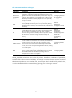
Table 3 Protection switchover technologies Technology Introduction Reference Ethernet Link Aggregation Ethernet link aggregation, most often simply called link aggregation, aggregates multiple physical Ethernet links into one logical link to increase link bandwidth beyond the limits of any one single link. This logical link is an aggregate link. It allows for link redundancy because the member physical links can dynamically back up one another.
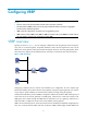
Configuring VRRP NOTE: • The term router in this document refers to both routers and Layer 3 firewalls. • The interfaces that VRRP involves can be only Layer 3 Ethernet interfaces and Layer 3 aggregate interfaces unless otherwise specified. • VRRP cannot be configured on an interface of an aggregation group. • VRRP versions include VRRPv2 and VRRPv3. VRRPv2 is based on IPv4, and VRRPv3 is based on IPv6. The web interface supports only configuration of IPv4 VRRP.
without configuration changes (such as dynamic routing protocols, route discovery protocols) when a router fails, and prevent network interruption due to a single link failure. Introduction to VRRP group VRRP combines a group of routers (including a master and multiple backups) on a LAN into a virtual router called VRRP group. A VRRP group has the following features: • A virtual router has a virtual IP address.
VRRP priority is in the range of 0 to 255. The greater the number, the higher the priority. Priorities 1 to 254 are configurable. Priority 0 is reserved for special uses and priority 255 for the IP address owner. When a router acts as the IP address owner, its running priority is always 255. That is, the IP address owner in a VRRP group acts as the master as long as it operates properly.
Packet format The master multicasts VRRP packets periodically to declare its existence. VRRP packets are also used for checking the parameters of the virtual router and electing the master. VRRP packets are encapsulated in IP packets, with the protocol number being 112. Figure 3 shows the format of a VRRPv2 packet and Figure 4 shows the format of a VRRPv3 packet.
• Count IP Addrs/Count IPv6 Addrs—Number of virtual IPv4 or IPv6 addresses for the VRRP group. A VRRP group can have multiple virtual IPv4 or IPv6 addresses. • Auth Type—Authentication type. 0 means no authentication, 1 means simple text authentication, and 2 means MD5 authentication. VRRPv3 does not support MD5 authentication. • Adver Int—Interval for sending advertisement packets. For VRRPv2, the interval is in seconds and defaults to 1.
Tracking a specified interface The interface tracking function expands the backup functionality of VRRP. It provides backup not only when the interface to which a VRRP group is assigned fails but also when other interfaces (such as uplink interfaces) on the router become unavailable. • If the uplink interface of a router in a VRRP group fails, usually the VRRP group cannot be aware of the uplink interface failure.
Assume that Router A is the master and therefore can forward packets to external networks, whereas Router B and Router C are backups and are thus in the state of listening. If Router A fails, Router B and Router C elect for a new master to forward packets to hosts on the LAN. Load sharing More than one VRRP group can be created on an interface of a router to allow the router to be the master of one VRRP group but a backup of another at the same time.
Configuring IPv4-based VRRP Configuring IPv4-based VRRP in the web interface Configuration task list Task Remarks Required Create a VRRP group on a VRRP interface and configure the virtual IP address. IMPORTANT: Creating a VRRP group • Before creating a VRRP group on an interface, you should first configure an IP address for the interface and make sure that the virtual IP address to be configured is in the same network segment as the IP address of the interface.
Figure 9 Creating a VRRP group Table 4 Configuration items Item Description VRID Set the group number of the VRRP group. Configure the virtual IP address of the VRRP group. If the VRRP interface connects to multiple subnets, you can configure multiple virtual IP addresses for the VRRP group to implement router backup on different subnets. IMPORTANT: • The virtual IP address cannot be all 0s (0.0.0.0), a broadcast address (255.255.255.255), a loopback address, any other invalid IP address (like 0.0.0.
group to be configured to enter the Modify VRRP Group page, and then click Display Track Config to expand the configuration items of the tracking function, as shown in Figure 10. Figure 10 Modifying VRRP group Table 6 Configuration items Item Description VRID Display group number of the VRRP group.
Item Description Configure the virtual IP address of the VRRP group. If an interface connects to multiple subnets, you can configure multiple virtual IP addresses for the VRRP group to implement router backup on different subnets. IMPORTANT: • The virtual IP address cannot be 0.0.0.0, 255.255.255.255, a loopback address, any other invalid IP address (like 0.0.0.1), or an address that does not belong to class A, B or C.
Item Description Set the interval at which the master sends VRRP advertisements. Advertise Time Excessive traffic or different timer setting on routers can cause the Backup timer to time out abnormally and trigger a change of the state. To solve this problem, you can prolong the time interval to send VRRP packets. IMPORTANT: Routers in the same VRRP group must use the same setting of advertisement interval.
Task Remarks Creating a VRRP group and configuring virtual IP address Required. Configuring router priority, preemptive mode and tracking function Optional. Configuring VRRP packet attributes Optional. Enabling the trap function for VRRP Optional.
By default, an ambiguous termination-enabled Layer 3 subinterface or VLAN interface drops broadcast and multicast packets they receive, instead of transmitting them. You can enable a Layer 3 Ethernet subinterface, or a VLAN interface configured with ambiguous termination to transmit broadcast/multicast packets within all VLANs whose VLAN packets are configured to be terminated by the subinterface or VLAN interface.
Step 1. Enter system view. Command Remarks system-view N/A • Enter Layer 3 Ethernet subinterface view: interface interface-type interface-number.subnumber 2. Enter interface view. • Enter Layer 3 aggregation subinterface Use either command. • Specify a VRRP control VLAN for the Use either command. view: interface route-aggregation interface-number.subnumber 3. Specify a VRRP control VLAN.
NOTE: • You can create up to 16 VRRP groups on an interface and up to 16 virtual IP addresses in a VRRP group. • When a router is the IP address owner in a VRRP group, HP recommends you not to use the IP address of the interface (virtual IP address of the VRRP group) to establish a neighbor relationship with the adjacent router, that is, not to use the network command to enable OSPF on the interface. • A VRRP group is removed after you remove all the virtual IP addresses configured for it.
NOTE: • The running priority of an IP address owner is always 255 and you do not need to configure it. An IP address owner always operates in preemptive mode. • If you configure an interface to be tracked or a track entry to be monitored on a router that is the IP address owner in a VRRP group, the configuration does not take effect. If the router is not the IP address owner in the VRRP group later, the configuration takes effect.
Enabling the trap function for VRRP When the trap function is enabled for VRRP, VRRP generates traps with severity level errors to report its key events. The traps are sent to the information center of the firewall, where you can configure whether to output the trap information and the output destination. For how to configure the information center, see System Management and Maintenance Configuration Guide. To enable the trap function for VRRP: Step Command Remarks 1. Enter system view.
Task Remarks Configuring VRRP packet attributes Optional.
Configuration prerequisites Before creating a VRRP group and configuring a virtual IPv6 address on an interface, configure an IPv6 address for the interface and make sure that it is in the same network segment as the virtual IPv6 address to be configured. Configuration procedure To create a VRRP group and configure its virtual IPv6 address: Step Command Remarks 1. Enter system view. system-view N/A 2. Enter the specified interface view. interface interface-type interface-number N/A 3.
To configure router priority, preemptive mode and interface tracking: Step Command Remarks 1. Enter system view. system-view N/A 2. Enter the specified interface view. interface interface-type interface-number N/A 3. Configure the priority of the router in the VRRP group. vrrp ipv6 vrid virtual-router-id priority priority-value Configure the router in the VRRP group to operate in preemptive mode and configure preemption delay of the VRRP group.
Step Command Remarks N/A 2. Enter the specified interface view. interface interface-type interface-number 3. Configure the authentication mode and authentication key when the VRRP groups send or receive VRRP packets. vrrp ipv6 vrid virtual-router-id authentication-mode simple key Configure the time interval for the master in the VRRP group to send VRRP advertisement. vrrp ipv6 vrid virtual-router-id timer advertise adver-interval 4. Optional. Authentication is not performed by default. Optional.
• If Firewall A operates properly, packets sent from Host A to Host B are forwarded by Firewall A. If GigabitEthernet 0/2 connecting Firewall A with the Internet becomes unavailable, packets sent from Host A to Host B are forwarded by Firewall B. Figure 12 Network diagram Configuring Firewall A # Configure the IP address of each interface and the zones. (Details not shown.) # Create VRRP group 1 on GigabitEthernet 0/1 and configure the virtual IP address as 202.38.160.111.
Figure 14 Configuring VRRP group attributes • Enter 110 in the Priority field. • Select Preemptive from the Preempt Mode field. • Enter 5 in the Delay field. • Select Simple from the Authentication field. • Enter hello in the Key field. • Enter 5 in the Advertise Time field. • Click Display Track Config. • Select GigabitEthernet0/2 from the Interface field, type 30 in the Reduced Priority field, and then click Add to add the interface to the list box of tracked interface. • Click Apply.
Figure 15 Creating VRRP group 1 • Enter 1 in the VRID field. • Enter 202.38.160.111 in the Virtual IP field and click Add to add the virtual IP address to the Virtual IP Members field. • Click Apply. # Configure VRRP group attributes. • On the VRRP group page of GigabitEthernet 0/1, click the 1 to enter the page shown in Figure 16. Figure 16 Configuring VRRP group attributes • Select Preemptive from the Preempt Mode field. • Enter 5 in the Delay field.
Verifying the configuration After the configuration, Host A can ping Host B. You can view the VRRP group information on GigabitEthernet 0/1 respectively on Firewall A and Firewall B. In VRRP group 1, Firewall A is the master and Firewall B is the backup router. Firewall A is responsible for forwarding packets sent from Host A to Host B. If the interface that connects Firewall A to the Internet fails, Host A can still ping Host B.
Configuring Firewall B system-view [FirewallB] interface gigabitethernet 0/1 [FirewallB-GigabitEthernet0/1] ip address 202.38.160.2 255.255.255.0 # Create VRRP group 1 and configure its virtual IP address as 202.38.160.111. [FirewallB-GigabitEthernet0/1] vrrp vrid 1 virtual-ip 202.38.160.111 # Configure Firewall B to operate in the preemptive mode, with the preemption delay set to 5 seconds.
# If Firewall A fails, display detailed information about VRRP group 1 on Firewall B. [FirewallB-GigabitEthernet0/1] display vrrp verbose IPv4 Standby Information: Run Mode : Standard Run Method : Virtual MAC Total number of virtual routers : 1 Interface GigabitEthernet0/1 VRID : 1 Adver Timer : 1 Admin Status : Up State : Master Config Pri : 100 Running Pri : 100 Preempt Mode : Yes Delay Time : 5 Auth Type : None Virtual IP : 202.38.160.
Figure 18 Network diagram Configuring Firewall A system-view [FirewallA] interface gigabitethernet 0/2 [FirewallA-GigabitEthernet0/2] ip address 202.38.160.1 255.255.255.0 # Create VRRP group 1 and configure its virtual IP address as 202.38.160.111. [FirewallA-GigabitEthernet0/2] vrrp vrid 1 virtual-ip 202.38.160.111 # Configure the priority of Firewall A in the VRRP group as 110, which is higher than that of Firewall B (100), so that Firewall A can become the master.
[FirewallB-GigabitEthernet0/2] vrrp vrid 1 authentication-mode simple hello # Configure the master to send VRRP packets every four seconds. [FirewallB-GigabitEthernet0/2] vrrp vrid 1 timer advertise 4 # Configure Firewall B to operate in preemptive mode, so that Firewall B can become the master after the priority of Firewall A decreases to a value lower than 100. Configure the preemption delay as five seconds to avoid frequent status switchover.
If interface GigabitEthernet 0/1 through which Firewall A connects to the Internet is not available, you can still successfully ping Host B on Host A. To view detailed information about the VRRP group, use the display vrrp verbose command. # If interface GigabitEthernet 0/1 on Firewall A is not available, detailed information about VRRP group 1 on Firewall A is displayed.
Use VRRP groups to implement load balancing and mutual backup between default gateways. Figure 19 Network diagram Configuring Firewall A # Configure the IP address of each interface and the zones. (Details not shown.) # Create VRRP group 1 on GigabitEthernet 0/1 and configure the virtual IP address as 202.38.160.111. • Select High Availability > VRRP from the navigation tree to enter the VRRP interfaces page.
Figure 21 Creating VRRP group 2 • Enter 2 in the VRID field. • Enter 202.38.160.112 in the Virtual IP field and click Add to add the virtual IP address to the Virtual IP Members field. • Click Apply. # Set the priority of Firewall A in VRRP group 1 to 110. • On the VRRP group page of GigabitEthernet 0/1, click the 1 to enter the page shown in Figure 22. icon corresponding to VRRP group Figure 22 Setting the priority of Firewall A in VRRP group 1 • Enter 110 in the Priority field.
• Select High Availability > VRRP from the navigation tree to enter the VRRP interfaces page. Click the icon corresponding to GigabitEthernet 0/1 to enter the VRRP Configuration on Interface page and then click Add. • Enter 1 in the VRID field. • Enter 202.38.160.111 in the Virtual IP field and click Add to add the virtual IP address to the Virtual IP Members field. • Click Apply. # Create VRRP group 2 on GigabitEthernet 0/1 and configure the virtual IP address as 202.38.160.112.
Figure 23 Network diagram Configuring Firewall A system-view [FirewallA] interface gigabitethernet 0/1 [FirewallA-GigabitEthernet0/1] ip address 202.38.160.1 255.255.255.0 # Create VRRP group 1 and configure its virtual IP address as 202.38.160.111. [FirewallA-GigabitEthernet0/1] vrrp vrid 1 virtual-ip 202.38.160.111 # Set the priority of Firewall A in VRRP group 1 to 110, which is higher than that of Firewall B (100), so that Firewall A can become the master in VRRP group 1.
IPv4 Standby Information: Run Mode : Standard Run Method : Virtual MAC Total number of virtual routers : 2 Interface GigabitEthernet0/1 VRID : 1 Adver Timer : 1 Admin Status : Up State : Master Config Pri : 110 Running Pri : 110 Preempt Mode : Yes Delay Time : 0 Auth Type : None Virtual IP : 202.38.160.111 Virtual MAC : 0000-5e00-0101 Master IP : 202.38.160.
Firewall A is the backup, Firewall B is the master and the host with the default gateway of 202.38.160.112/24 accesses the Internet through Firewall B. NOTE: To implement load balancing between the VRRP groups, be sure to configure the default gateway as 202.38.160.111 or 202.38.160.112 on the hosts on network segment 202.38.160.0/24.
[FirewallA-GigabitEthernet0/1] vrrp ipv6 vrid 1 priority 110 # Configure Firewall A to operate in preemptive mode so that it can become the master whenever it operates properly; configure the preemption delay as five seconds to avoid frequent status switchover. [FirewallA-GigabitEthernet0/1] vrrp ipv6 vrid 1 preempt-mode timer delay 5 # Enable Firewall A to send RA messages, so that Host A can learn the default gateway address.
Interface GigabitEthernet0/1 VRID : 1 Adver Timer : 100 Admin Status : Up State : Backup Config Pri : 100 Running Pri : 100 Preempt Mode : Yes Delay Time : 5 Become Master : 4200ms left Auth Type : None Virtual IP : FE80::10 Master IP : FE80::1 1::10 The output shows that in VRRP group 1 Firewall A is the master, Firewall B is the backup and packets sent from Host A to Host B are forwarded by Firewall A. When Firewall A fails, you can still ping Firewall B successfully on Host A.
Virtual MAC : 0000-5e00-0201 Master IP : FE80::1 The output shows that after Firewall A resumes normal operation, it becomes the master, and packets sent from host A to host B are forwarded by Firewall A. VRRP interface tracking configuration example Network requirements • Firewall A and Firewall B belong to VRRP group 1 with the virtual IPv6 addresses of 1::10/64 and FE80::10.
# Set the authentication mode of VRRP group 1 as simple and authentication key to hello. [FirewallA-GigabitEthernet0/2] vrrp ipv6 vrid 1 authentication-mode simple hello # Set the interval on Firewall A for sending VRRP advertisements to 400 centiseconds.
VRID : 1 Adver Timer : 400 Admin Status : Up State : Master Config Pri : 110 Running Pri : 110 Preempt Mode : Yes Delay Time : 5 Auth Type : Simple Key : hello Virtual IP : FE80::10 Virtual MAC : 0000-5e00-0201 Master IP : FE80::1 1::10 VRRP Track Information: Track Interface: GE0/1 State : Up Pri Reduced : 30 # Display detailed information about VRRP group 1 on Firewall B.
Master IP : FE80::2 VRRP Track Information: Track Interface: GE0/1 State : Down Pri Reduced : 30 # When interface GigabitEthernet 0/1 on Firewall A fails, display detailed information about VRRP group 1 on Firewall B.
Figure 26 Network diagram Configuring Firewall A system-view [FirewallA] ipv6 [FirewallA] interface gigabitethernet 0/1 [FirewallA-GigabitEthernet0/1] ipv6 address fe80::1 link-local [FirewallA-GigabitEthernet0/1] ipv6 address 1::1 64 # Create VRRP group 1 and set its virtual IPv6 addresses to FE80::10 and 1::10.
# Set the priority of Firewall B in VRRP group 2 to 110, which is higher than that of Firewall A (100), so that Firewall B can become the master in VRRP group 2. [FirewallB-GigabitEthernet0/1] vrrp ipv6 vrid 2 priority 110 Verifying the configuration To verify your configuration, use the display vrrp ipv6 verbose command. # Display detailed information about the VRRP group on Firewall A.
Interface GigabitEthernet0/1 VRID : 2 Adver Timer : 100 Admin Status : Up State : Master Config Pri : 110 Running Pri : 110 Preempt Mode : Yes Delay Time : 0 Auth Type : None Virtual IP : FE80::20 1::20 Virtual MAC : 0000-5e00-0202 Master IP : FE80::2 The output shows that in VRRP group 1, Firewall A is the master, Firewall B is the backup and the host with the default gateway of 1::10/64 accesses the Internet through Firewall A; in VRRP group 2, Firewall A is the backup, Firewall B
Frequent VRRP state transition Analysis The VRRP advertisement interval is set too short. Solution Increase the interval to sent VRRP advertisement or introduce a preemption delay.
Configuring stateful failover NOTE: The stateful failover configuration is available only in the web interface. Overview Introduction to stateful failover Some customers require the key entries or access points of their networks, such as the Internet access point of an enterprise or a database server of a bank, to be highly reliable to ensure continuous data transmission.
Figure 28 Network diagram for stateful failover Internet GE0/0 GE0/0 GE0/1 Device A GE0/1 Device B Failover link GE0/2 GE0/2 Internal network Host A Host B Service backup The two devices exchange state negotiation messages through the failover link periodically. After the two devices enter the synchronization state, they back up the services of each other to make sure that the services on them are consistent.
Figure 29 Stateful failover state diagram Configuring stateful failover NOTE: The firewall does not support the IPsec failover function. Select High Reliability > Stateful Failover from the navigation tree to enter the stateful failover configuration page, as shown in Figure 30. The upper part of the page allows you to configure stateful failover parameters, and the lower part of the page displays the current stateful failover state and the configuration synchronization state.
Table 7 Configuration items Item Description Enable/disable the stateful failover feature. Enable Stateful Failover IMPORTANT: The configuration items are available only after you select the Enable Stateful Failover box. Enable/disable the session failover function. Session Failover IMPORTANT: To enable stateful failover for NAT, ALG, and ASPF services, you must enable session failover. Enable/disable the IPsec failover function.
Item Description Click Modify Backup Interface to enter the Backup Interface Configuration page, and then you can: • Select one or more interfaces from the Optional Backup Interface(s) list, and then click the << button to add the selected interfaces to the Backup Interface(s) list. • Select one or more interfaces from the Backup Interface(s) list, and then click the >> button to remove the selected interfaces from the list.
Network requirements In Figure 28, Device A and Device B are deployed for stateful failover in an enterprise network to provide Internet access. They both run NAT to provide IP address translation. It is required to: • Configure the devices to back up each other, so that when one device fails, the other device takes over the services to ensure service continuity. • Enable automatic configuration synchronization from Device A (active device) to Device B (standby device). Configuration procedure 1.
Figure 32 Configuring stateful failover 2. Configure Device B. Except the Main Device for Configuration Synchronization and Auto Synchronization settings that are not needed for Device B, other settings on Device B are consistent with those on Device A. (Details not shown.
Configuring IPC IPC commands are available only at CLI and applicable to stateful failover network environments. Overview Inter-Process Communication (IPC) provides a reliable communication mechanism among processing units, typically CPUs. IPC is typically used on a distributed device or in an IRF fabric to provide reliable inter-card or inter-device transmission. This section describes the basic IPC concepts. Node An IPC node is an independent IPC-capable processing unit, typically, a CPU.
Figure 33 Relationship between a node, link and channel Node 1 Application 2 Application 1 IPC Application 3 ha nn el 2 Ch a nn e C l1 Application 1 IPC Application 3 Application 2 Node 2 Packet sending modes IPC uses one of the following modes to send packets for upper layer application modules: • Unicast—One node sends packets to another node. • Multicast—One node sends packets to several other nodes. This mode includes broadcast, a special multicast.
Displaying and maintaining IPC Task Command Remarks Display IPC node information. display ipc node [ | { begin | exclude | include } regular-expression ] Available in any view Display channel information for a node. display ipc channel { node node-id | self-node } [ | { begin | exclude | include } regular-expression ] Available in any view Display queue information for a node.
Configuring a collaboration group NOTE: Collaboration group configuration is available only in the Web interface. Overview As shown in Figure 34, LAN users Host A, Host B and Host C access the Internet through Device B. When the link connecting Device A and Device B goes down, the traffic switches from Device B to the standby device Device C because dynamic routing is enabled in the network.
Configuration task list Task Remarks Required. In this procedure, ports are assigned to a collaboration group. Configuring a collaboration group Collaboration groups are not manually created. By default, there are 24 collaboration groups in the system. The group numbers are from 1 to 24. By default, none of these collaboration groups contain any member port. Displaying the status of a collaboration group and its member ports Optional. Display the status of a collaboration group and its member ports.
Figure 36 Configuring a collaboration group To assign a port to the collaboration group, select the box in front of the port and click Apply. Ports that are not selected do not belong to the collaboration group. NOTE: • A port can belong to only one collaboration group. • The page for configuring a collaboration group displays all the current member ports of the collaboration group, as well as the ports that do no belong to any collaboration group.
Title Description • Up—The port is physically up. Interface Status • Down—The port is physically down. • Linkgroup-down—The port is administratively down. Collaboration group configuration example Network requirements As shown in Figure 37, LAN users Host A, Host B, and Host C access the Internet through the Firewall. Device B serves as a backup for the Firewall.
Figure 38 Assigning GigabitEthernet 0/1 and GigabitEthernet 0/2 to Collaboration Group 1 • Select the boxes in front of GigabitEthernet 0/1 and GigabitEthernet 0/2. • Click Apply. Verifying the configuration # Unplug the cable connecting Device A to GigabitEthernet 0/1 on the Firewall, and check the status of Collaboration Group 1 and its member ports. • Select High Reliability > Collaboration Group from the navigation tree, and check the status of Collaboration Group 1.
Figure 39 Checking the status of Collaboration Group 1 • Click the icon for Collaboration Group 1 and check the status of its member ports. The status of GigabitEthernet 0/1 is Down, and that of GigabitEthernet 0/2 is Linkgroup-down, as shown in Figure 40.
Figure 40 Checking the status of Collaboration Group 1's member ports Configuration guidelines When the firewall is connected to another device through multiple ports, do not assign these ports to the same collaboration group. Otherwise, when one port goes down, its peer port on the remote device may be set to the Link-group down state, in which case, all the ports will fail to be brought up.
Track configuration NOTE: The track configuration is available only at the CLI. Feature and hardware compatibility Feature F1000-A-EI/S-EI F1000-E F5000 Firewall module Associating track with BFD No No Yes No Track overview Introduction to collaboration The track module works between application and detection modules, as shown in Figure 41. It shields the differences between various detection modules from application modules.
Collaboration between the track module and a detection module The detection module sends the detection result of the associated tracked object to the track module, which then changes the status of the track entry: • If the tracked object functions normally, for example, the target interface is up or the target network is reachable, the state of the track entry is Positive.
Track configuration task list To implement the collaboration function, establish associations between the track module and the detection modules, and between the track module and the application modules. Complete these tasks to configure the track module: Task Remarks Associating the track module with a detection module Associating track with NQA Required. Associating track with BFD Use any of the approaches.
NOTE: If the specified NQA test group or the reaction entry in the track entry does not exist, the status of the track entry is Invalid. Associating track with BFD BFD supports the control packet mode and echo mode. Only echo-mode BFD can be associated with a track entry. When associated with a track entry, the BFD functions as follows: • If the BFD detects the link fails, it informs the track entry of the link failure. The track module then sets the track entry to the Negative state.
Step Command Remarks N/A 1. Enter system view. system-view 2. Create a track entry, associate it with the interface management module to monitor the physical status of an interface, and specify the delay time for the track module to notify the associated application module when the track entry status changes.
Step Command Remarks 3. Create a VRRP group and configure its virtual IP address. vrrp vrid virtual-router-id virtual-ip virtual-address No VRRP group is created by default. 4. Associate a track entry with a VRRP group. vrrp [ ipv6 ] vrid virtual-router-id track track-entry-number [ reduced priority-reduced | switchover ] No track entry is specified for a VRRP group by default. NOTE: • VRRP tracking is not valid on an IP address owner.
Step Command Remarks • Approach 1: 2. Associate the static route with a track entry to check the reachability of the next hop.
• Next hop • Default outgoing interface • Default next hop Configuration prerequisites Before you associate track with PBR, create a policy or a policy node and configure the match criteria as well. Configuration procedure To associate track with PBR: Step Command Remarks 1. Enter system view. system-view N/A 2. Create a policy or policy node and enter PBR policy node view. policy-based-route policy-name [ deny | permit ] node node-number N/A • Define a packet length match criterion: 3.
Associating track with interface backup Interface backup allows interfaces on a device to back up each other, with the active interface transmitting data and the standby interfaces staying in backup state. When the active interface or the link where the active interface resides fails, and data cannot be transmitted, a standby interface is brought up to transmit data, enhancing the reliability of the network.
Track configuration examples VRRP-track-NQA collaboration configuration example (the master monitors the uplinks) Network requirements • As shown in Figure 42, Host A needs to access Host B on the Internet. The default gateway of Host A is 10.1.1.10/24. • Firewall A and Firewall B belong to VRRP group 1, which has the virtual IP address 10.1.1.10. • When Router A works normally, packets from Host A to Host B are forwarded through Firewall A.
# Start the NQA test. [FirewallA] nqa schedule admin test start-time now lifetime forever 3. Configure a track entry on Firewall A: # Configure track entry 1, and associate it with reaction entry 1 of the NQA test group (with the administrator admin, and the operation tag test). [FirewallA] track 1 nqa entry admin test reaction 1 4. Configure VRRP on Firewall A: # Create VRRP group 1, and configure the virtual IP address 10.1.1.10 for the group.
Auth Type : Simple Virtual IP : 10.1.1.10 Key Virtual MAC : 0000-5e00-0101 Master IP : 10.1.1.1 : hello VRRP Track Information: Track Object : 1 State : Positive Pri Reduced : 30 # Display detailed information about VRRP group 1 on Firewall B.
Run Method : Virtual MAC Total number of virtual routers : 1 Interface GigabitEthernet0/1 VRID : 1 Adver Timer : 5 Admin Status : Up State : Master Config Pri : 100 Running Pri : 100 Preempt Mode : Yes Delay Time : 5 Auth Type : Simple Key : hello Virtual IP : 10.1.1.10 Virtual MAC : 0000-5e00-0101 Master IP : 10.1.1.2 The output shows that when a fault is on the link between Firewall A and Router A, the priority of Firewall A decreases to 80.
Figure 43 Network diagram Internet Firewall A Master Virtual Router Virtual IP address: 192.168.0.10 Firewall B Backup GE0/1 192.168.0.101/24 GE0/1 192.168.0.102/24 L2 switch BFD probe packets VRRP packets Configuration procedure 1. Configure VRRP on Firewall A: system-view [FirewallA] interface gigabitethernet 0/1 # Create VRRP group 1, and configure the virtual IP address 192.168.0.10 for the group. Set the priority of Firewall A in VRRP group 1 to 110.
[FirewallB-GigabitEthernet 0/1] vrrp vrid 1 virtual-ip 192.168.0.10 [FirewallB-GigabitEthernet 0/1] vrrp vrid 1 track 1 switchover [FirewallB-GigabitEthernet 0/1] return 5. Verify the configuration: # Display the detailed information of VRRP group 1 on Firewall A.
The output shows that when the status of the track entry becomes Positive, Firewall A is the master and Firewall B the backup. # Enable VRRP state debugging and BFD event debugging on Firewall B. terminal debugging terminal monitor debugging vrrp state debugging bfd event # When Firewall A fails, the following output is displayed on Firewall B. *Dec 17 14:44:34:142 2008 FirewallB BFD/7/EVENT:Send sess-down Msg, [Src:192.168.0.102,Dst:192.168.0.
Figure 44 Network diagram Configuration procedure 1. Configure BFD on Firewall A: # Configure the source address of BFD echo packets as 10.10.10.10. system-view [FirewallA] bfd echo-source-ip 10.10.10.10 2. Create the track entry to associate with the BFD session on Firewall A: # Create track entry 1 for the BFD session on Firewall A to check whether the uplink device with the IP address 1.1.1.2 is reachable. [FirewallA] track 1 bfd echo interface gigabitethernet 0/1 remote ip 1.1.1.
[FirewallB] interface gigabitethernet 0/2 [FirewallB-GigabitEthernet 0/2] vrrp vrid 1 virtual-ip 192.168.0.10 [FirewallB-GigabitEthernet 0/2] return 5. Verify the configuration: # Display the detailed information of the VRRP group on Firewall A.
The output shows that when the status of track entry 1 becomes Positive, Firewall A is the master and Firewall B the backup. # When the uplink of Firewall A goes down, the status of track entry 1 becomes Negative. display track 1 Track ID: 1 Status: Negative Duration: 0 days 0 hours 0 minutes 32 seconds Notification delay: Positive 0, Negative 0 (in seconds) Reference object: BFD session: Packet type: Echo Interface : GigabitEthernet 0/1 Remote IP : 1.1.1.2 Local IP : 1.1.1.
Static routing-track-NQA collaboration configuration example Network requirements As shown in Figure 45, Firewall A, Router A, Router B, and Firewall B are connected to two segments 20.1.1.0/24 and 30.1.1.0/24. Configure static routes on these firewalls so that the two segments can communicate with each other, and configure firewall backup to improve reliability of the network. Firewall A is the default gateway of the hosts in segment 20.1.1.0/24. Two static routes to 30.1.1.
# Configure a static route to 30.1.1.0/24, with the address of the next hop as 10.1.1.2 and the default priority 60. This static route is associated with track entry 1. system-view [FirewallA] ip route-static 30.1.1.0 24 10.1.1.2 track 1 # Configure a static route to 30.1.1.0/24, with the address of the next hop as 10.3.1.3 and the priority 80. [FirewallA] ip route-static 30.1.1.0 24 10.3.1.3 preference 80 # Configure a static route to 10.2.1.4, with the address of the next hop as 10.1.1.2.
system-view [FirewallB] ip route-static 20.1.1.0 24 10.2.1.2 track 1 # Configure a static route to 20.1.1.0/24, with the address of the next hop as 10.4.1.3 and the default priority 80. [FirewallB] ip route-static 20.1.1.0 24 10.4.1.3 preference 80 # Configure a static route to 10.1.1.1, with the address of the next hop as 10.2.1.2. [FirewallB] ip route-static 10.1.1.1 24 10.2.1.2 # Create an NQA test group with the administrator admin and the operation tag test.
10.1.1.1/32 Direct 0 0 127.0.0.1 InLoop0 10.2.1.0/24 Static 60 0 10.1.1.2 GE0/1 10.3.1.0/24 Direct 0 0 10.3.1.1 GE0/2 10.3.1.1/32 Direct 0 0 127.0.0.1 InLoop0 20.1.1.0/24 Direct 0 0 20.1.1.1 GE0/3 20.1.1.1/32 Direct 0 0 127.0.0.1 InLoop0 30.1.1.0/24 Static 60 0 10.1.1.2 GE0/1 127.0.0.0/8 Direct 0 0 127.0.0.1 InLoop0 127.0.0.1/32 Direct 0 0 127.0.0.
PING 30.1.1.1: 56 data bytes, press CTRL_C to break Reply from 30.1.1.1: bytes=56 Sequence=1 ttl=254 time=2 ms Reply from 30.1.1.1: bytes=56 Sequence=2 ttl=254 time=1 ms Reply from 30.1.1.1: bytes=56 Sequence=3 ttl=254 time=1 ms Reply from 30.1.1.1: bytes=56 Sequence=4 ttl=254 time=2 ms Reply from 30.1.1.1: bytes=56 Sequence=5 ttl=254 time=1 ms --- 30.1.1.1 ping statistics --5 packet(s) transmitted 5 packet(s) received 0.
• The static route with Firewall A as the next hop has a higher priority, and is the master route. If this route is available, Firewall B forwards packets to 20.1.1.0/24 through Firewall A. • The static route with Router as the next hop acts as the backup route. • Configure static routing-track-BFD collaboration to determine whether the master route is available in real time.
# Configure track entry 1 that is associated with the BFD session to check whether Firewall A can communicate with the next hop Firewall B of the static route. [FirewallB] track 1 bfd echo interface gigabitethernet 0/1 remote ip 10.2.1.1 local ip 10.2.1.2 4. Configure Router: # Configure a static route to 30.1.1.0/24, with the address of the next hop as 10.4.1.2. system-view [Router] ip route-static 30.1.1.0 24 10.4.1.2 # Configure a static route to 20.1.1.
[FirewallA] display track all Track ID: 1 Status: Negative Duration: 0 days 0 hours 0 minutes 32 seconds Notification delay: Positive 0, Negative 0 (in seconds) Reference object: BFD Session: Packet type: Echo Interface : GigabitEthernet 0/1 Remote IP : 10.2.1.2 Local IP : 10.2.1.1 # Display the routing table of Firewall A. [FirewallA] display ip routing-table Routing Tables: Public Destinations : 9 Destination/Mask Proto 10.2.1.0/24 Routes : 9 Pre Cost NextHop Interface Direct 0 0 10.2.1.
Reply from 20.1.1.1: bytes=56 Sequence=1 ttl=254 time=2 ms Reply from 20.1.1.1: bytes=56 Sequence=2 ttl=254 time=1 ms Reply from 20.1.1.1: bytes=56 Sequence=3 ttl=254 time=1 ms Reply from 20.1.1.1: bytes=56 Sequence=4 ttl=254 time=1 ms Reply from 20.1.1.1: bytes=56 Sequence=5 ttl=254 time=1 ms --- 20.1.1.1 ping statistics --5 packet(s) transmitted 5 packet(s) received 0.
[FirewallA] interface gigabitethernet 0/1 [FirewallA-GigabitEthernet0/1] vrrp vrid 1 virtual-ip 10.1.1.10 # Set the priority of Firewall A in VRRP group 1 to 110. [FirewallA-GigabitEthernet0/1] vrrp vrid 1 priority 110 # Configure to monitor track entry 1 and specify the priority decrement as 30. [FirewallA-GigabitEthernet0/1] vrrp vrid 1 track 1 reduced 30 4.
The output shows that in VRRP group 1, Firewall A is the master and Firewall B is a backup. Packets from Host A to Host B are forwarded through Firewall A. # Shut down the uplink interface GigaibtEthernet 0/2 on Firewall A. [FirewallA-GigabitEthernet0/1] interface gigabitethernet 0/2 [FirewallA-GigabitEthernet0/2] shutdown After shutting down the uplink interface on Firewall A, you can still successfully ping Host B on Host A. Use the display vrrp command to view information about VRRP group 1.
Configuring NQA NOTE: The NQA configuration is available only at the CLI. Overview Network Quality Analyzer (NQA) can perform various types of tests and collect network performance and service quality parameters such as delay jitter, time for establishing a TCP connection, time for establishing an FTP connection, and file transfer rate. With the NQA test results, you can diagnose and locate network faults, be aware of network performance in time and take proper actions to correct any problems.
• Upon the detection results, the track module changes the status of the track entry and informs the associated application module. The track module works between the application modules and the detection modules. It hides the differences among detection modules from application modules. • The application module takes actions when the tracked object changes its state. The following describes how a static route is monitored through collaboration: 1. NQA monitors the reachability to 192.168.0.88. 2.
NOTE: The counting for the average or accumulate threshold type is performed per test, but that for the consecutive type is performed since the test group is started. 3. Triggered actions: { { 4. none—NQA only records events for terminal display; it does not send trap information to the network management server. trap-only—NQA records events and sends trap messages to the network management server.
Figure 49 Relationship between the NQA client and NQA server Not all test types require the NQA server. Only the TCP, UDP echo, or UDP jitter test requires both the NQA client and server, as shown in Figure 49. You can create multiple TCP or UDP listening services on the NQA server. Each listens to a specific destination address and port number. Make sure the destination IP address and port number for a listening service on the server are the same as those configured for the test group on the NQA client.
Task Remarks Configuring SNMP tests Configuring TCP tests Configuring UDP echo tests Configuring DLSw tests Configuring the collaboration function Optional. Configuring threshold monitoring Optional. Configuring the NQA statistics collection function Optional. Configuring the history records saving function Optional. Configuring optional parameters for an NQA test group Optional. Configuring a schedule for an NQA test group Required.
Creating an NQA test group Create an NQA test group before you configure NQA tests. To create an NQA test group: Step Command Remarks N/A 1. Enter system view. system-view 2. Create an NQA test group and enter the NQA test group view. nqa entry admin-name operation-tag In the NQA test group view, you can specify the test type You can use the nqa entry command to enter the test type view of an NQA test group with test type configured.
Step 8. Command Configure the source interface for ICMP echo requests. The requests take the IP address of the source interface as their source IP address when no source IP address is specified.. Remarks Optional. source interface interface-type interface-number By default, no source interface is configured for probe packets. The specified source interface must be up; otherwise, no ICMP echo requests can be sent out. Optional. By default, no source IP address is configured. 9.
Step 3. Configure the test type as DHCP and enter test type view. Command Remarks type dhcp N/A 4. Specify an interface to perform DHCP tests. operation interface interface-type interface-number 5. Configure optional parameters. See "Configuring optional parameters for an NQA test group" By default, no interface is configured to perform DHCP tests. The specified interface must be up; otherwise, no probe packets can be sent out. Optional.
Step Command Remarks Optional. By default, the operation type for the FTP is get, which means obtaining files from the FTP server. 6. Configure the operation type. operation { get | put } 7. Configure a login username. username name By default, no login username is configured. 8. Configure a login password. password password By default, no login password is configured. 9. Specify a file to be transferred between the FTP server and the FTP client.
Step Command Remarks Optional. 5. Configure the source IP address of request packets. By default, no source IP address is specified. source ip ip-address The source IP address must be the IP address of a local interface. The local interface must be up; otherwise, no probe packets can be sent out. Optional. 6. Configure the operation type. operation { get | post } By default, the operation type for the HTTP is get, which means obtaining data from the HTTP server. 7.
Configuring UDP jitter tests Step Command Remarks 1. Enter system view. system-view N/A 2. Enter NQA test group view. nqa entry admin-name operation-tag N/A 3. Configure the test type as UDP jitter and enter test type view. type udp-jitter N/A 4. Configure the destination address of UDP packets. By default, no destination IP address is configured. destination ip ip-address By default, no destination port number is configured. 5. Configure the destination port of UDP packets. 6.
Step Command Remarks 13. Configure optional parameters. See "Configuring optional parameters for an NQA test group" Optional. NOTE: The probe count command specifies the number of probe operations during one UDP jitter test. The probe packet-number command specifies the number of probe packets sent in each UDP jitter probe operation. Configuring SNMP tests SNMP tests of an NQA test group are used to test the time the NQA client takes to send an SNMP packet to the SNMP agent and receive a response.
TCP tests require cooperation between the NQA server and the NQA client. Before you start TCP tests, configure a TCP listening service on the NQA server. For more information about the TCP listening service configuration, see "Configuring the NQA server." To configure TCP tests: Step Command Remarks 1. Enter system view. system-view N/A 2. Enter NQA test group view. nqa entry admin-name operation-tag N/A 3. Configure the test type as TCP and enter test type view. type tcp N/A 4. 5.
Step 3. 4. Configure the test type as UDP echo and enter test type view. Configure the destination address of UDP packets. Command Remarks type udp-echo N/A By default, no destination IP address is configured. destination ip ip-address 5. Configure the destination port of UDP packets. destination port port-number 6. Configure the size of the data field in each UDP packet. data-size size 7. 8. Configure the string to be filled in the data field of each UDP packet.
Step Configure the destination address of probe packets. 4. Command Remarks destination ip ip-address By default, no destination IP address is configured. Optional. 5. 6. By default, no source IP address is specified. Configure the source IP address of probe packets. source ip ip-address Configure optional parameters. See "Configuring optional parameters for an NQA test group" The source IP address must be the IP address of a local interface.
Step Command Remarks 1. Enter system view. system-view N/A 2. Enter NQA test group view. nqa entry admin-name operation-tag N/A 3. Enter test type view of the test group.
Configuring the NQA statistics collection function NQA groups tests completed in a time period for a test group, and calculates the test result statistics. The statistics form a statistics group. To view information about the statistics groups, use the display nqa statistics command. To set the interval for collecting statistics, use the statistics interval command.
To configure the history records saving function of an NQA test group: Step Command Remarks 1. Enter system view. system-view N/A 2. Enter NQA test group view. nqa entry admin-name operation-tag N/A 3. Enter NQA test type view. type { dhcp | dlsw | ftp | http | icmp-echo | snmp | tcp | udp-echo | udp-jitter } N/A 4. Enable the saving of the history records of the NQA test group. history-record enable By default, history records of the NQA test group are not saved. 5. 6.
Step Command Remarks Optional. 5. 6. Configure the interval between two consecutive tests for a test group. frequency interval Configure the number of probe operations to be performed in one test. probe count times By default, the interval between two consecutive tests for a test group is 0 milliseconds. Only one test is performed. If the last test is not completed when the interval specified by the frequency command is reached, a new test does not start. Optional.
Step Command Remarks Enter system view. system-view N/A 2. Configure a schedule for an NQA test group. nqa schedule admin-name operation-tag start-time { hh:mm:ss [ yyyy/mm/dd ] | now } lifetime { lifetime | forever } 3. Configure the maximum number of tests that the NQA client can simultaneously perform. 1. now specifies the test group starts testing immediately. forever specifies that the tests do not stop unless you use the undo nqa schedule command. Optional.
Figure 50 Network diagram Configuration procedure NOTE: Before you make the configuration, make sure the devices can reach each other. # Create an ICMP echo test group and specify 10.2.2.2 as the destination IP address for ICMP echo requests to be sent. system-view [Firewall] nqa entry admin test [Firewall-nqa-admin-test] type icmp-echo [Firewall-nqa-admin-test-icmp-echo] destination ip 10.2.2.2 # Configure 10.1.1.2 as the next hop IP address for ICMP echo requests.
# Stop the ICMP echo tests after a period of time. [Firewall] undo nqa schedule admin test # Display the results of the last ICMP echo test. [Firewall] display nqa result admin test NQA entry (admin admin, tag test) test results: Destination IP address: 10.2.2.2 Send operation times: 10 Receive response times: 10 Min/Max/Average round trip time: 2/5/3 Square-Sum of round trip time: 96 Last succeeded probe time: 2007-08-23 15:00:01.
Configuration procedure # Create a DHCP test group and specify interface GigabitEthernet 0/1 to perform NQA DHCP tests. system-view [Firewall] nqa entry admin test [Firewall-nqa-admin-test] type dhcp [Firewall-nqa-admin-test-dhcp] operation interface gigabitethernet 0/1 # Enable the saving of history records. [Firewall-nqa-admin-test-dhcp] history-record enable [Firewall-nqa-admin-test-dhcp] quit # Start DHCP tests.
Figure 52 Network diagram Configuration procedure NOTE: Before you make the configuration, make sure the devices can reach each other. # Create an FTP test group. system-view [Firewall] nqa entry admin test [Firewall-nqa-admin-test] type ftp # Specify the IP address of the FTP server 10.2.2.2 as the destination IP address for FTP tests. [Firewall-nqa-admin-test-ftp] destination ip 10.2.2.2 # Specify 10.1.1.1 as the source IP address for probe packets.
Failures due to no connection: 0 Failures due to sequence error: 0 Failures due to internal error: 0 Failures due to other errors: 0 Packet(s) arrived late: 0 # Display the history of FTP tests. [Firewall] display nqa history admin test NQA entry (admin admin, tag test) history record(s): Index Response Status Time 1 173 Succeeded 2007-11-22 10:07:28.
# Start HTTP tests. [Firewall] nqa schedule admin test start-time now lifetime forever # Stop HTTP tests after a period of time. [Firewall] undo nqa schedule admin test # Display results of the last HTTP test. [Firewall] display nqa result admin test NQA entry (admin admin, tag test) test results: Destination IP address: 10.2.2.2 Send operation times: 1 Receive response times: 1 Min/Max/Average round trip time: 64/64/64 Square-Sum of round trip time: 4096 Last succeeded probe time: 2007-11-22 10:12:47.
system-view [FirewallB] nqa server enable [FirewallB] nqa server udp-echo 10.2.2.2 9000 2. Configure Firewall A: # Create a UDP jitter test group. system-view [FirewallA] nqa entry admin test [FirewallA-nqa-admin-test] type udp-jitter # Configure UDP jitter packets to use 10.2.2.2 as the destination IP address and port 9000 as the destination port. [FirewallA-nqa-admin-test-udp-jitter] destination ip 10.2.2.
Negative SD sum: 38 Negative DS sum: 52 Negative SD average: 10 Negative DS average: 10 Negative SD square sum: 460 Negative DS square sum: 754 One way results: Max SD delay: 15 Max DS delay: 16 Min SD delay: 7 Min DS delay: 7 Number of SD delay: 10 Number of DS delay: 10 Sum of SD delay: 78 Sum of DS delay: 85 Square sum of SD delay: 666 Square sum of DS delay: 787 SD lost packet(s): 0 DS lost packet(s): 0 Lost packet(s) for unknown reason: 0 # Display the statistics of UDP jitter tests.
Sum of SD delay: 3705 Sum of DS delay: 3891 Square sum of SD delay: 45987 Square sum of DS delay: 49393 SD lost packet(s): 0 DS lost packet(s): 0 Lost packet(s) for unknown reason: 0 NOTE: The display nqa history command does not show the results of UDP jitter tests. To know the result of a UDP jitter test, use the display nqa result command to view the probe results of the latest NQA test, or use the display nqa statistics command to view the statistics of NQA tests.
# Stop the SNMP tests after a period of time. [FirewallA] undo nqa schedule admin test # Display the results of the last SNMP test. [FirewallA] display nqa result admin test NQA entry (admin admin, tag test) test results: Destination IP address: 10.2.2.2 Send operation times: 1 Receive response times: 1 Min/Max/Average round trip time: 50/50/50 Square-Sum of round trip time: 2500 Last succeeded probe time: 2007-11-22 10:24:41.
[FirewallB] nqa server tcp-connect 10.2.2.2 9000 2. Configure Firewall A: # Create a TCP test group. system-view [FirewallA] nqa entry admin test [FirewallA-nqa-admin-test] type tcp # Configure TCP probe packets to use 10.2.2.2 as the destination IP address and port 9000 as the destination port. [FirewallA-nqa-admin-test-tcp] destination ip 10.2.2.2 [FirewallA-nqa-admin-test-tcp] destination port 9000 # Enable the saving of history records.
Figure 57 Network diagram Configuration procedure NOTE: Before you make the configuration, make sure the devices can reach each other. 1. Configure Firewall B: # Enable the NQA server and configure a listening service to listen to IP address 10.2.2.2 and UDP port 8000. system-view [FirewallB] nqa server enable [FirewallB] nqa server udp-echo 10.2.2.2 8000 2. Configure Firewall A: # Create a UDP echo test group.
Failures due to sequence error: 0 Failures due to internal error: 0 Failures due to other errors: 0 Packet(s) arrived late: 0 # Display the history of UDP echo tests. [FirewallA] display nqa history admin test NQA entry (admin admin, tag test) history record(s): Index Response Status Time 1 25 Succeeded 2007-11-22 10:36:17.9 DLSw test configuration example Network requirements As shown in Figure 58, configure NQA DLSw tests to test the response time of the DLSw device.
Last succeeded probe time: 2007-11-22 10:40:27.7 Extended results: Packet loss in test: 0% Failures due to timeout: 0 Failures due to disconnect: 0 Failures due to no connection: 0 Failures due to sequence error: 0 Failures due to internal error: 0 Failures due to other errors: 0 Packet(s) arrived late: 0 # Display the history of DLSw tests. [Firewall] display nqa history admin test NQA entry (admin admin, tag test) history record(s): Index Response Status Time 1 19 Succeeded 2007-11-22 10:40:27.
[Firewall-nqa-admin-test] type icmp-echo # Configure ICMP echo requests to use 10.2.2.1 as the destination IP address. [Firewall-nqa-admin-test-icmp-echo] destination ip 10.2.1.1 # Configure the device to perform tests at an interval of 100 milliseconds. [Firewall-nqa-admin-test-icmp-echo] frequency 100 # Create reaction entry 1. If the number of consecutive probe failures reaches 5, collaboration with other modules is triggered.
Status: Negative Notification delay: Positive 0, Negative 0 (in seconds) Reference object: NQA entry: admin test Reaction: 1 # Display brief information about active routes in the routing table on Firewall. [Firewall] display ip routing-table Routing Tables: Public Destinations : 4 Destination/Mask Proto 10.2.1.0/24 10.2.1.2/32 Routes : 4 Pre Cost NextHop Interface Direct 0 0 10.2.1.2 GE0/1 Direct 0 0 127.0.0.1 InLoop0 127.0.0.0/8 Direct 0 0 127.0.0.1 InLoop0 127.0.0.
Configuring Ethernet link aggregation Feature and hardware compatibility Feature F1000-A-EI/S-EI F1000-E F5000 Firewall module Limiting the number of Selected ports for an aggregation group No No Yes No Overview Ethernet link aggregation, or simply link aggregation, combines multiple physical Ethernet ports into one logical link, called an aggregate link. Link aggregation delivers the following benefits: • Increases bandwidth beyond the limits of any single link.
NOTE: • On a Layer 3 aggregate interface, you can create subinterfaces. The Layer 3 aggregate subinterfaces are logical interfaces that operate at the network layer. They can receive VLAN tagged packets for their Layer 3 aggregate interface. • The rate of an aggregate interface equals the total rate of its member ports in the Selected state, and its duplex mode is the same as the selected member ports.
NOTE: • Class-two configurations made on an aggregate interface are automatically synchronized to all its member ports. These configurations are retained on the member ports even after the aggregate interface is removed. • Any class-two configuration change may affect the aggregation state of link aggregation member ports and ongoing traffic. To make sure that you are aware of the risk, the system displays a warning message every time you attempt to change a class-two configuration setting on a member port.
Table 12 LACP priorities Type Description Used by two peer devices (or systems) to determine which one is superior in link aggregation. System LACP priority In dynamic link aggregation, the system that has higher system LACP priority sets the Selected state of member ports on its side first and then the system that has lower priority sets port state accordingly. Port aggregation priority 3. Remarks Determines the likelihood of a member port to be selected on a system.
Selecting a reference port The system selects a reference port from the member ports that are in the up state and have the same class-two configurations as the aggregate interface. The candidate ports are sorted by aggregation priority, duplex, and speed in the following order: • Lowest aggregation priority value • Full duplex/high speed • Full duplex/low speed • Half duplex/high speed • Half duplex/low speed The one at the top is selected as the reference port.
NOTE: • The maximum number of selected ports in a static aggregation group is 8. • To ensure stable aggregation state and service continuity, do not change port attributes or class-two configurations on any member port. • If a static aggregation group has reached the limit on Selected ports, any port joins the group is placed in the Unselected state to avoid traffic interruption on the current Selected ports.
Figure 62 Setting the state of a member port in a dynamic aggregation group Meanwhile, the system with the higher system ID, being aware of the aggregation state changes on the remote system, sets the aggregation state of local member ports the same as their peer ports.
Load sharing criteria for link aggregation groups In a link aggregation group, traffic may be load-shared across the selected member ports based on a set of criteria, depending on your configuration.
Figure 63 Creating a Layer 2 static link aggregation group Table 15 shows the detailed configurations for a Layer 2 static link aggregation group. Table 15 Configuration items Item Description Enter Link Aggregation Interface ID. Select Bridge-Aggregation to create a Layer 2 static aggregation group, and set the aggregate interface number. Select port(s) for the link aggregation interface. Select one or multiple ports to be assigned to the link aggregation group from the chassis front panel.
Figure 64 Creating a Layer 3 static link aggregation group Table 16 shows the detailed configurations for a Layer 3 static link aggregation group. Table 16 Configuration items Item Description Enter Link Aggregation Interface ID. Select Route-Aggregation to create a Layer 3 static aggregation group, and set the aggregate interface number. Select port(s) for the link aggregation interface. Select one or multiple ports to be assigned to the link aggregation group from the chassis front panel.
Figure 65 Displaying information about an aggregate interface Table 17 Field description Field Description Aggregation interface Type and ID of the aggregate interface. Link Type Type of the aggregate interface. Partner ID ID of the remote device, including its LACP priority and MAC address. Selected Ports Number of Selected ports in each link aggregation group. (Only Selected ports can transmit and receive user data.) Standby Ports Number of Unselected ports in each link aggregation group.
Figure 66 Network diagram Configuration procedure # Create static Layer 2 link aggregation group 1. Select Network > Link Aggregation from the navigation tree, and then click Create to enter the page as shown in Figure 67. Figure 67 Creating Layer 2 static link aggregation group 1 1. Select the Bridge-Aggregation option and set the link aggregation interface ID to 1. 2. Select GigabitEthernet 0/1, GigabitEthernet 0/2, and GigabitEthernet 0/3 on the chassis front panel. 3. Click Apply.
Layer 3 static link aggregation configuration example Network requirements As shown in Figure 68, aggregate the Layer 3 Ethernet ports on each firewall to form a static link aggregation group, balancing incoming/outgoing traffic across the member ports. Figure 68 Network diagram Configuration procedure # Create Layer 3 static link aggregation group 1. Select Network > Link Aggregation from the navigation tree, and then click Create to enter the page as shown in Figure 69.
2. Select GigabitEthernet 0/1, GigabitEthernet 0/2, and GigabitEthernet 0/3 on the chassis front panel. 3. Click Apply. Configuring link aggregation at the CLI Ethernet link aggregation configuration task list Task Configuring an aggregation group Configuring an aggregate interface Remarks Configuring a static aggregation group Configuring a dynamic aggregation group Perform either task. Configuring the description of an aggregate interface or subinterface Optional.
NOTE: To guarantee a successful static aggregation, make sure that the ports at both ends of each link are in the same aggregation state. To configure a Layer 2 static aggregation group: Step Command Remarks 1. Enter system view. system-view N/A 2. Create a Layer 2 aggregate interface and enter Layer 2 aggregate interface view.
Step 4. Command a. Enter Layer 3 Ethernet interface view: interface interface-type interface-number Assign an Ethernet interface to the aggregation group. b. Assign the Ethernet interface to the aggregation group: port link-aggregation group number Remarks Repeat this step to assign more Layer 3 Ethernet interfaces to the aggregation group. Optional. By default, the aggregation priority of a port is 32768. 5. Assign the port an aggregation priority.
Step 4. 5. 6. Command Remarks Configure the aggregation group to operate in dynamic aggregation mode. link-aggregation mode dynamic By default, an aggregation group operates in static aggregation mode. Exit to system view. quit N/A a. Enter Layer 2 Ethernet interface view: interface interface-type interface-number Assign an Ethernet interface to the aggregation group. b.
Step 6. Command Assign an Ethernet interface to the aggregation group. Remarks a. Enter Layer 3 Ethernet interface view: interface interface-type interface-number b. Assign the Ethernet interface to the aggregation group: port link-aggregation group number Repeat this step to assign more Layer 3 Ethernet interfaces to the aggregation group. Optional. 7. 8. Assign the port an aggregation priority. Set the LACP timeout interval on the port to the short timeout interval (1 second).
Step 3. Command Configure the description of the aggregate interface or subinterface. Remarks Optional. By default, the description of an interface is in the format of interface-name Interface, such as Bridge-Aggregation1 Interface. description text Configuring the MTU of a Layer 3 aggregate interface or subinterface The maximum transmission unit (MTU) of an interface affects IP packets fragmentation and reassembly on the interface.
Limiting the number of Selected ports for an aggregation group The bandwidth of an aggregate link increases along with the number of selected member ports. To avoid congestion caused by insufficient Selected ports on an aggregate link, you can set the minimum number of Selected ports required for bringing up the specific aggregate interface.
Step Set the maximum number of Selected ports for the aggregation group. 4. Command Remarks link-aggregation selected-port maximum number By default, the maximum number of Selected ports allowed in an aggregation group depends on only the hardware capabilities of the member ports.
Step 3. Restore the default settings for the aggregate interface or subinterface. Command Remarks default N/A Configuring load sharing for link aggregation groups You can determine how traffic is load-shared in a link aggregation group by configuring load sharing criteria. The criteria can be service port numbers, IP addresses, or IP protocols carried in packets, or any combination. You can configure global or group-specific load sharing criteria.
Displaying and maintaining Ethernet link aggregation Task Display information for an aggregate interface or multiple aggregate interfaces. Command display interface [ bridge-aggregation | route-aggregation ] [ brief [ down ] ] [ | { begin | exclude | include } regular-expression ] display interface { bridge-aggregation | route-aggregation } interface-number [ brief ] [ | { begin | exclude | include } regular-expression ] Remarks Available in any view Display the local system ID.
Network requirements As shown in Figure 70, configure a Layer 2 static aggregation group on Device A and Device B respectively, and enable VLAN 10 at one end of the aggregate link to communicate with VLAN 10 at the other end, and VLAN 20 at one end to communicate with VLAN 20 at the other end. Enable traffic to be load-shared across aggregation group member ports based on the source and destination MAC addresses.
# Configure Layer 2 aggregate interface Bridge-Aggregation 1 as a trunk port and assign it to VLANs 10 and 20. [DeviceA] interface bridge-aggregation 1 [DeviceA-Bridge-Aggregation1] port link-type trunk [DeviceA-Bridge-Aggregation1] port trunk permit vlan 10 20 Please wait... Done. Configuring GigabitEthernet0/1... Done. Configuring GigabitEthernet0/2... Done. Configuring GigabitEthernet0/3... Done.
Network requirements As shown in Figure 71, configure two Layer 2 static aggregation groups (1 and 2) on Device A and Device B respectively, and enable VLAN 10 at one end of the aggregate link to communicate with VLAN 10 at the other end, and VLAN 20 at one end to communicate with VLAN 20 at the other end.
# Configure Layer 2 aggregate interface Bridge-Aggregation 1 as a trunk port and assign it to VLAN 10. [DeviceA] interface bridge-aggregation 1 [DeviceA-Bridge-Aggregation1] port link-type trunk [DeviceA-Bridge-Aggregation1] port trunk permit vlan 10 Please wait... Done. Configuring GigabitEthernet0/1... Done. Configuring GigabitEthernet0/2... Done.
The output shows that link aggregation groups 1 and 2 are both load-shared Layer 2 static aggregation groups and each contains two Selected ports. # Display all the group-specific load sharing criteria on Device A.
[DeviceA-GigabitEthernet0/2] port link-aggregation group 1 [DeviceA-GigabitEthernet0/2] quit [DeviceA] interface gigabitethernet 0/3 [DeviceA-GigabitEthernet0/3] port link-aggregation group 1 [DeviceA-GigabitEthernet0/3] quit # Configure the global link-aggregation load sharing criteria as the source and destination IP addresses of packets. [DeviceA] link-aggregation load-sharing mode source-ip destination-ip 2. Configure Device B in the same way as you configure Device A. (Details not shown.) 3.
Figure 73 Network diagram Configuration procedure 1. Configure Device A: # Create Layer 3 aggregate interface Route-Aggregation 1, configure it to perform load sharing based on source IP address, and configure an IP address and subnet mask for the aggregate interface. system-view [DeviceA] interface route-aggregation 1 [DeviceA-Route-Aggregation1] link-aggregation load-sharing mode source-ip [DeviceA-Route-Aggregation1] ip address 192.168.1.
BAGG -- Bridge-Aggregation, RAGG -- Route-Aggregation Aggregation Mode: S -- Static, D -- Dynamic Loadsharing Type: Shar -- Loadsharing, NonS -- Non-Loadsharing Actor System ID: 0x8000, 000f-e2ff-0001 AGG AGG Interface Mode Partner ID Select Unselect Share Ports Type Ports ------------------------------------------------------------------------------RAGG1 S none 2 0 Shar RAGG2 S none 2 0 Shar The output shows that link aggregation groups 1 and 2 are both load-shared Layer 3 static agg
Configuring BFD NOTE: • The term router in this document refers to both routers and firewalls running routing protocols. • The BFD configuration is available only at the CLI. Feature and hardware compatibility Feature F1000-A-EI/S-EI F1000-E F5000 Firewall module BFD No No Yes No Introduction to BFD Devices must quickly detect communication failures so that measures can be taken in time to ensure service continuity and enhance network availability.
Operation of BFD Figure 74 BFD session establishment (on OSPF routers) BFD session establishment: 1. A protocol sends Hello messages to discover neighbors and establish neighborships. 2. After establishing neighborships, the protocol notifies BFD of the neighbor information, including destination and source addresses. 3. BFD uses the information to establish BFD sessions.
BFD detection methods • Single-hop detection—Detects the IP connectivity between two directly connected systems. • Multi-hop detection—Detects any of the paths between two systems. These paths have multiple hops and may be overlapped. • Bidirectional detection—Sends detection packets at two sides of a bidirectional link to detect the bidirectional link status, finding link failures in milliseconds.
echo packets have a similar format as BFD control packets (except that the Desired Min TX Interval and Required Min RX Interval fields are null) with UDP port number 3785. Figure 76 illustrates the packet format. Figure 76 BFD packet format • Vers—Protocol version. The protocol version is 1. • Diag—This bit indicates the reason for the last transition of the local session from up to some other state. Table 18 lists the states.
• Demand (D)—If set, Demand mode is active in the transmitting system (the system wishes to operate in Demand mode, knows that the session is up in both directions, and is directing the remote system to cease the periodic transmission of BFD Control packets). If clear, Demand mode is not active in the transmitting system. • Reserved (R)—This byte must be set to zero on transmit, and ignored on receipt. • Detect Mult—Detection time multiplier. • Length—Length of the BFD control packet, in bytes.
Configuration prerequisites Before you configure BFD basic functions, complete the following tasks: • Configure the network layer addresses of the interfaces so that adjacent nodes are reachable to each other at the network layer • Configure the routing protocols that support BFD Configuration procedure To configure BFD basic functions: Step Command Remarks 1. Enter system view. system-view N/A 2. Specify the mode for establishing a BFD session.
Step Command Remarks Optional. Configure the minimum interval for receiving BFD control packets. 8. bfd min-receive-interval value For relevant information, see the description of the Required Min RX Interval field in "BFD packet format." The value ranges from 10 to 1000 and the default is 400. Optional. Configure the detection time multiplier. 9. bfd detect-multiplier value For relevant information, see the description of the Detect Mult field in "BFD packet format." 5 by default.
NOTE: • For the description of the snmp-agent trap enable bfd command, see System Management and Maintenance Command Reference. • For the information center configuration, see System Management and Maintenance Configuration Guide. Displaying and maintaining BFD Task Command Remarks Display information about BFD-enabled interfaces. display bfd interface [ verbose ] [ | { begin | exclude | include } regular-expression ] Available in any view Display information about enabled BFD debugging.
Support and other resources Contacting HP For worldwide technical support information, see the HP support website: http://www.hp.
Conventions This section describes the conventions used in this documentation set. Command conventions Convention Description Boldface Bold text represents commands and keywords that you enter literally as shown. Italic Italic text represents arguments that you replace with actual values. [] Square brackets enclose syntax choices (keywords or arguments) that are optional. { x | y | ... } Braces enclose a set of required syntax choices separated by vertical bars, from which you select one.
Network topology icons Represents a generic network device, such as a router, switch, or firewall. Represents a routing-capable device, such as a router or Layer 3 switch. Represents a generic switch, such as a Layer 2 or Layer 3 switch, or a router that supports Layer 2 forwarding and other Layer 2 features. Represents a firewall. Port numbering in examples The port numbers in this document are for illustration only and might be unavailable on your device.
Index ACDEFHINORSTV Displaying the status of a collaboration group and its member ports,63 A Associating the track module with a detection module,70 E Associating the track module with an application module,72 Enabling IPC performance statistics,59 Enabling the NQA client,102 Availability evaluation,1 Enabling Trap,171 Availability requirements,1 C Ethernet link aggregation configuration examples at the CLI,156 Collaboration group configuration example,64 F Configuration guidelines,164 Feature a
Track overview,68 V Troubleshooting VRRP,49 VRRP overview,4 177