
R3721-F3210-F3171-HP High-End Firewalls High Availability Configuration Guide-6PW101


95
Reply from 20.1.1.1: bytes=56 Sequence=1 ttl=254 time=2 ms
Reply from 20.1.1.1: bytes=56 Sequence=2 ttl=254 time=1 ms
Reply from 20.1.1.1: bytes=56 Sequence=3 ttl=254 time=1 ms
Reply from 20.1.1.1: bytes=56 Sequence=4 ttl=254 time=1 ms
Reply from 20.1.1.1: bytes=56 Sequence=5 ttl=254 time=1 ms
--- 20.1.1.1 ping statistics ---
5 packet(s) transmitted
5 packet(s) received
0.00% packet loss
round-trip min/avg/max = 1/1/2 ms
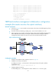
VRRP-track-interface management collaboration configuration
example (the master monitors the uplink interface)
Network requirements
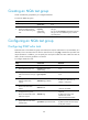
• As shown in Figure 47, Host A needs to access Host B on the Internet. The default gateway of Host
A i s 10 .1.1.10 / 24 .
• Firewall A and Firewall B belong to VRRP group 1, whose virtual IP address is 10.1.1.10.
• When Firewall A works normally, packets from Host A to Host B are forwarded through Firewall A.
When VRRP detects that a fault is on the uplink interface of Firewall A through the interface
management module, packets from Host A to Host B are forwarded through Firewall B.
Figure 47 Network diagram
Configuration procedure
1. Configure the IP address of each interface as shown in Figure 47.
2. Configure a track entry on Firewall A:
# Configure track entry 1, and associate it with the physical status of the uplink interface
GigabitEthernet 0/2.
[FirewallA] track 1 interface gigabitethernet 0/2
3. Configure VRRP on Firewall A:
# Create VRRP group 1, and configure the virtual IP address 10.1.1.10 for the group.