
R3721-F3210-F3171-HP High-End Firewalls High Availability Configuration Guide-6PW101


157
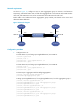
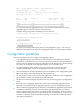
Network requirements
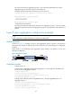
As shown in Figure 70, configure a Layer 2 static aggregation group on Device A and Device B
respectively, and enable VLAN 10 at one end of the aggregate link to communicate with VLAN 10 at the
other end, and VLAN 20 at one end to communicate with VLAN 20 at the other end.
Enable traffic to be load-shared across aggregation group member ports based on the source and
destination MAC addresses.
Figure 70 Network diagram
Configuration procedure
1. Configure Device A:
# Create VLAN 10, and assign port GigabitEthernet 0/4 to VLAN 10.
<DeviceA> system-view
[DeviceA] vlan 10
[DeviceA-vlan10] port gigabitethernet 0/4
[DeviceA-vlan10] quit
# Create VLAN 20, and assign port GigabitEthernet 0/5 to VLAN 20.
[DeviceA] vlan 20
[DeviceA-vlan20] port gigabitethernet 0/5
[DeviceA-vlan20] quit
# Create Layer 2 aggregate interface Bridge-Aggregation 1.
[DeviceA] interface bridge-aggregation 1
[DeviceA-Bridge-Aggregation1] quit
# Assign ports GigabitEthernet 0/1 through GigabitEthernet 0/3 to link aggregation group 1.
[DeviceA] interface gigabitethernet 0/1
[DeviceA-GigabitEthernet0/1] port link-aggregation group 1
[DeviceA-GigabitEthernet0/1] quit
[DeviceA] interface gigabitethernet 0/2
[DeviceA-GigabitEthernet0/2] port link-aggregation group 1
[DeviceA-GigabitEthernet0/2] quit
[DeviceA] interface gigabitethernet 0/3
[DeviceA-GigabitEthernet0/3] port link-aggregation group 1
[DeviceA-GigabitEthernet0/3] quit
GE0/2
GE0/1
GE0/3
Link aggregation 1
GE0/2
GE0/1
GE0/3
BAGG1 BAGG1
Device A Device B
VLAN 10
VLAN 20
GE0/4
GE0/5
VLAN 10
VLAN 20
GE0/4
GE0/5