
R3721-F3210-F3171-HP High-End Firewalls High Availability Configuration Guide-6PW101


163
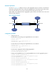
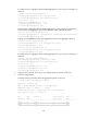
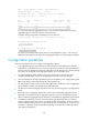
Figure 73 Network diagram
Configuration procedure
1. Configure Device A:
# Create Layer 3 aggregate interface Route-Aggregation 1, configure it to perform load sharing
based on source IP address, and configure an IP address and subnet mask for the aggregate
interface.
<DeviceA> system-view
[DeviceA] interface route-aggregation 1
[DeviceA-Route-Aggregation1] link-aggregation load-sharing mode source-ip
[DeviceA-Route-Aggregation1] ip address 192.168.1.1 24
[DeviceA-Route-Aggregation1] quit
# Assign Layer 3 Ethernet interfaces GigabitEthernet 0/1 and GigabitEthernet 0/2 to aggregation
group 1.
[DeviceA] interface gigabitethernet 0/1
[DeviceA-GigabitEthernet0/1] port link-aggregation group 1
[DeviceA-GigabitEthernet0/1] quit
[DeviceA] interface gigabitethernet 0/2
[DeviceA-GigabitEthernet0/2] port link-aggregation group 1
[DeviceA-GigabitEthernet0/2] quit
# Create Layer 3 aggregate interface Route-Aggregation 2, configure its link aggregation group
to perform load sharing based on destination IP address, and configure an IP address and subnet
mask for the aggregate interface.
[DeviceA] interface route-aggregation 2
[DeviceA-Route-Aggregation2] link-aggregation load-sharing mode destination-ip
[DeviceA-Route-Aggregation2] ip address 192.168.2.1 24
[DeviceA-Route-Aggregation2] quit
# Assign Layer 3 Ethernet interfaces GigabitEthernet 0/3 and GigabitEthernet 0/4 to aggregation
group 2.
[DeviceA] interface gigabitethernet 0/3
[DeviceA-GigabitEthernet0/3] port link-aggregation group 2
[DeviceA-GigabitEthernet0/3] quit
[DeviceA] interface gigabitethernet 0/4
[DeviceA-GigabitEthernet0/4] port link-aggregation group 2
[DeviceA-GigabitEthernet0/4] quit
2. Configure Device B in the same way as you configure Device A. (Details not shown.)
3. Verify the configurations:
# Display summary information about all aggregation groups on Device A.
[DeviceA] display link-aggregation summary
Aggregation Interface Type: