
R3721-F3210-F3171-HP High-End Firewalls High Availability Configuration Guide-6PW101


52
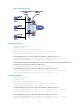
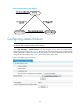
Figure 28 Network diagram for stateful failover
Service backup
The two devices exchange state negotiation messages through the failover link periodically. After the two
devices enter the synchronization state, they back up the services of each other to make sure that the
services on them are consistent. If one device fails, the other device can take over the services by using
VRRP or a dynamic routing protocol (such as OSPF).
Configuration synchronization
To implement service backup, the key service configurations on the two devices must be consistent. With
the configuration synchronization function, you can synchronize such configurations from the active
device to the standby device through the failover link, instead of making repeated configurations on both
devices.
With auto synchronization, the active device synchronizes all its configurations to the standby device at
a time. After that, when its configuration is changed, the active device automatically synchronizes the
new configuration to the standby device.
Introduction to stateful failover states
The stateful failover states include:
• Silence—Indicates that the device has just started, or is transiting from synchronization state to
independence state.
• Independence—Indicates that the silence timer has expired, but no failover link is established.
• Synchronization—Indicates that the device has completed state negotiation with the other device
and is ready for data backup.
The following figure shows state relations.
Internet
Internal
network
Device A
Host A Host B
Device B
Failover link
GE0/1 GE0/1
GE0/0 GE0/0
GE0/2 GE0/2