
R3721-F3210-F3171-HP High-End Firewalls High Availability Configuration Guide-6PW101


87
Static routing-track-NQA collaboration configuration example
Network requirements
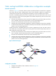
As shown in Figure 45, Firewall A, Router A, Router B, and Firewall B are connected to two segments
20.1.1.0/24 and 30.1.1.0/24. Configure static routes on these firewalls so that the two segments can
communicate with each other, and configure firewall backup to improve reliability of the network.
Firewall A is the default gateway of the hosts in segment 20.1.1.0/24. Two static routes to 30.1.1.0/24
exist on Firewall A, with the next hop being Router A and Router B respectively. These two static routes
back up each other, where:
• The static route with Router A as the next hop has a higher priority, and is the master route. If this
route is available, Firewall A forwards packets to 30.1.1.0/24 through Router A.
• The static route with Router B as the next hop acts as the backup route.
• Configure static routing-track-NQA collaboration to determine whether the master route is available
in real time. If the master route is unavailable, the backup route takes effect, and Firewall A forwards
packets to 30.1.1.0/24 through Router B.
Similarly, Firewall B is the default gateway of the hosts in segment 30.1.1.0/24. Two static routes to
20.1.1.0/24 exist on Firewall B, with the next hop being Router A and Router B respectively. These two
static routes back up each other, where:
• The static route with Router A as the next hop has a higher priority, and is the master route. If this
route is available, Firewall B forwards pack e t s t o 2 0 .1.1. 0 / 24 t h r o u g h R o u t e r A .
• The static route with Router B as the next hop acts as the backup route.
• Configure static routing-track-NQA collaboration to determine whether the master route is available
in real time. If the master route is unavailable, the backup route takes effect, and Firewall B forwards
packets to 20.1.1.0/24 through Router B.
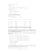
Figure 45 Network diagram
Configuration procedure
1. Configure the IP address of each interface as shown in Figure 45.
2. Configure Firewall A: