HP High-End Firewalls NAT and ALG Configuration Guide Part number: 5998-2649 Software version: F1000-A-EI&F1000-S-EI: R3721 F5000: F3210 F1000-E: F3171 Firewall module: F3171 Document version: 6PW101-20120719
Legal and notice information © Copyright 2012 Hewlett-Packard Development Company, L.P. No part of this documentation may be reproduced or transmitted in any form or by any means without prior written consent of Hewlett-Packard Development Company, L.P. The information contained herein is subject to change without notice.
Contents Configuring NAT ·························································································································································· 1 Overview············································································································································································ 1 Introduction to NAT ·······························································································································
Configuration prerequisites ·································································································································· 34 Enabling NAT-PT ··················································································································································· 35 Configuring a NAT-PT prefix ································································································································ 35 Configuring IPv4/IPv6 a
Configuring NAT Overview Introduction to NAT Network Address Translation (NAT) provides a way of translating the IP address in an IP packet header to another IP address. In practice, NAT is primarily used to allow users using private IP addresses to access public networks. With NAT, a small number of public IP addresses are used to enable a large number of internal hosts to access the Internet. Thus, NAT effectively alleviates the depletion of IP addresses.
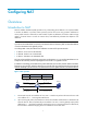
3. The external server responds to the internal host with an IP packet whose destination IP address is 20.1.1.1. Upon receiving the packet, the NAT device checks the IP header, looks into its NAT table for the mapping, replaces the destination address with the private address of 192.168.1.3, and then sends the new packet to the internal host. The NAT operation is transparent to the terminals involved. The external server believes that the IP address of the internal PC is 20.1.1.
NOTE: The number of public IP addresses that a NAT device needs is usually far less than the number of internal hosts because not all internal hosts access external networks at the same time. The number of public IP addresses is related to the number of internal hosts that might access external networks simultaneously during peak hours. NAPT Network Address Port Translation (NAPT) is a variation of basic NAT.
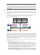
source port number but different destination addresses and destination port numbers, different NAPT mappings apply so that the source address and port number are mapped to the same external IP address but different port numbers. The NAT device allows the hosts only on the corresponding external networks where these destination addresses reside to access the internal network. This mode is secure but inconvenient for communication among hosts that connect to different NAT devices.
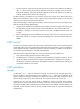
Figure 4 Operation of NAT DNS mapping A DNS mapping entry records the domain name, public address, public port number, and protocol type of an internal server. Upon receiving a DNS reply, the NAT-enabled interface matches the domain name in the message against the DNS mapping entries. If a match is found, the private address of the internal server is found and the interface replaces the public IP address in the reply with the private IP address.
To solve the problem, the low-priority address pool attribute is introduced to NAT. You can configure address pools on the two devices to have different priorities. For example, suppose that two addresses pools, 100.0.0.1 through 100.0.0.5 (A), and 100.0.0.6 through 100.0.0.10 (B), are configured on the two devices. You can configure A as the low-priority address pool on a device and configure B as the low-priority address pool on the other device.
Configuring an internal server Table 3 Internal server configuration task list Task Remarks Required. Creating an internal server After you map the private IP address/port number of an internal server to a public IP address/port number, hosts in external networks can access the server located in the private network. Optional.
Table 4 Configuration items Item Description Index Specify the index of an address pool. Start IP Address Specify the start IP address of the address pool. End IP Address Specify the end IP address of the address pool. The end IP address must be identical to or higher than the start IP address. Configure the address pool as a low-priority or a non low-priority address pool. Low priority IMPORTANT: This configuration item is applicable to the stateful failover networking only.
Item Description Specify an ACL for dynamic NAT. You cannot associate an ACL with multiple NAT address pools, or associate an ACL with both Easy IP and an address pool. ACL IMPORTANT: On some devices, the rules of an ACL applied on an interface cannot conflict with one another, that is, rules with the same source IP address, destination IP address, and VPN instance are considered as a conflict.
Figure 8 Static NAT configuration page Figure 9 Adding static address mapping Table 6 Configuration item Item Description Specify a name of the VPN instance to which the internal IP addresses belong. Internal VPN Instance If no internal VPN instance is specified, this indicates that the internal address is a common private network address. Internal IP Address Enter an internal IP address for the static address mapping. Specify a name of the VPN instance to which the external IP addresses belong.
Item Description Specify the ACL number. ACL If the acl-number argument is specified, the device performs NAT for the packets matching a specific ACL rule, and no longer matches the packets against the interzone policy. Enabling static NAT on an interface Select Firewall > NAT Policy > Static NAT from the navigation tree to enter the page shown in Figure 8.
Figure 11 Internal server configuration page Figure 12 Adding an internal server Table 8 Configuration items Item Description Interface Specify an interface to which the internal server policy is applied. Protocol Type Select or specify the type of the protocol to be carried by IP.
Item Description Specify a name of the VPN instance to which the external address belongs. Global VPN Instance External IP Address If no global VPN instance is specified, this indicates that the external IP address is a common public network address that does not belong to any VPN instance. Specify the public IP address for the internal server. You can enter an IP address, or use the IP address of an interface. Specify the global port number(s) for the internal server.
Figure 13 Adding the DNS-MAP Table 9 Configuration items Item Description Protocol Select the protocol supported by an internal server. Global IP Specify the external IP address of the internal server. Global Port Specify the port number of the internal server. Domain Specify the domain name of the internal server. NAT configuration example Network requirements As shown in Figure 14, a company has three public IP addresses ranging from 202.38.1.1/24 to 202.38.1.
Figure 15 Defining ACL 2001 • Enter 2001 in ACL Number. • Select Config in Match Order. • Click Apply. • Click the icon in the Operation column corresponding to ACL 2001 to enter the ACL 2001 configuration page, click Add, and then perform the following operations, as shown in Figure 16. Figure 16 Configuring ACL 2001 to permit users on network 10.110.10.0/24 to access the Internet • Select Permit in Operation. • Select the Source IP Address box and then enter 10.110.10.0. • Enter 0.0.0.
Figure 17 Configuring ACL 2001 to prohibit other users to access the Internet • Select Deny for Operation. • Click Apply. # Configure a NAT address pool. • Select Firewall > NAT Policy > Dynamic NAT from the navigation tree, click Add, and then perform the following operations, as shown in Figure 18. Figure 18 Configuring NAT address pool 0 • Enter 0 in Index. • Enter 202.38.1.2 in Start IP Address. • Enter 202.38.1.3 in End IP Address. • Click Apply. # Configure dynamic NAT.
Figure 19 Configuring dynamic NAT • Select GigabitEthernet0/1 for Interface. • Enter 2001 in ACL. • Select PAT for Address Transfer. • Enter 0 in Address Pool Index. • Click Apply. Internal server configuration example Network requirements As shown in Figure 20, a company provides two Web servers and one FTP server for external users to access. The internal network address is 10.110.0.0/16. The internal address for the FTP server is 10.110.10.3/16, for the Web server 1 is 10.110.10.
• Select Firewall > NAT Policy > Internal Server from the navigation tree, click Add in the Internal Server field, and then perform the following operations, as shown in Figure 21. Figure 21 Configuring an internal FTP server • Select GigabitEthernet0/1 for Interface. • Select 6(TCP) for Protocol Type. • Select the option next to Assign IP Address, and then enter 202.38.1.1 in Global IP. • Select the upper option next to Global Port and enter 21. • Enter 10.110.10.3 in Internal IP.
Figure 22 Configuring internal Web server 1 • Select GigabitEthernet0/1 for Interface. • Select 6(TCP) for Protocol Type. • Select the option next to Assign IP Address, and then enter 202.38.1.1 for Global IP. • Select the upper option next to Global Port and enter 80. • Enter 10.110.10.1 in Internal IP. • Enter 80 in Internal Port. • Click Apply. # Configure Web server 2. • Click Add in the Internal Server field and perform the following operations, as shown in Figure 23.
Figure 23 Configuring internal Web server 2 • Select GigabitEthernet0/1 for Interface. • Select 6(TCP) for Protocol Type. • Select the option next to Assign IP Address, and then enter 202.38.1.1 for Global IP. • Select the upper option next to Global Port and enter 8080. • Enter 10.110.10.2 in Internal IP. • Enter 80 in Internal Port. • Click Apply.
NOTE: • If the NAT configuration (address translation or internal server configuration) on an interface is changed, save the configuration and reboot the device (or use the reset nat session command to manually clear the relevant NAT entries), to avoid problems.
To configure net-to-net static NAT: Step Command 1. Enter system view. system-view 2. Configure a net-to-net static NAT mapping. nat static [ acl-number ] net-to-net local-network [ vpn-instance local-name ] global-network [ vpn-instance global-name ] { netmask-length | netmask } 3. Return to system view. quit 4. Enter interface view. interface interface-type interface-number 5. Enable static NAT on the interface.
Step Command Remarks 1. Enter system view. system-view N/A 2. Configure an address pool. nat address-group group-number start-address end-address Not necessary when the router provides only Easy IP, where an interface's public IP address is used as the translated IP address. To configure an address group: Step Command 1. Enter system view. system-view 2. Create an address group and enter its view. nat address-group group-number 3. Add a member to the address group.
Configuring NAPT With a specific ACL associated with an address pool or interface address, NAPT translates the source address of a packet permitted by the ACL into an IP address of the address pool or the interface address, with using the port information. To configure NAPT: Step Command 1. Enter system view. system-view 2. Enter interface view. interface interface-type interface-number 3.
CAUTION: • The firewall supports using the interface address as the external address of an internal server, which is the Easy IP feature. If you want to specify an interface, the interface must be a loopback interface and must already exist. • If you configure an internal server using Easy IP but do not configure an IP address for the interface, the internal server configuration does not take effect.
NAT configuration examples One-to-one static NAT configuration example Network requirements As shown in Figure 24, an internal host 10.110.10.8/24 uses public address 202.38.1.100 to access the Internet. Figure 24 Network diagram GE0/1 10.110.10.1/24 Host 10.110.10.8/24 GE0/2 202.38.1.1/16 Internet Server Firewall Configuration procedure # Configure the IP addresses for the interfaces. (Details not shown.) # Configure a one-to-one static NAT mapping system-view [Firewall] nat static 10.110.
# Configure address pool 1. system-view [Firewall] nat address-group 1 202.38.1.2 202.38.1.3 # Configure ACL 2001, permitting only users from network segment 10.110.10.0/24 to access the Internet. [Firewall] acl number 2001 [Firewall-acl-basic-2001] rule permit source 10.110.10.0 0.0.0.255 [Firewall-acl-basic-2001] rule deny [Firewall-acl-basic-2001] quit # Associate address pool 1 and ACL 2001 with the outbound interface GigabitEthernet 0/2.
system-view [Firewall] interface gigabitethernet 0/2 # Configure the internal FTP server. [Firewall-GigabitEthernet0/2] nat server protocol tcp global 202.38.1.1 21 inside 10.110.10.3 ftp # Configure the internal Web server 1. [Firewall-GigabitEthernet0/2] nat server protocol tcp global 202.38.1.1 80 inside 10.110.10.1 www # Configure the internal Web server 2. [Firewall-GigabitEthernet0/2] nat server protocol tcp global 202.38.1.1 8080 inside 10.110.10.
system-view [Firewall] interface gigabitethernet 0/2 # Configure the internal Web server. [Firewall-GigabitEthernet0/2] nat server protocol tcp global 202.38.1.2 inside 10.110.10.1 www # Configure the internal FTP server. [Firewall-GigabitEthernet0/2] nat server protocol tcp global 202.38.1.2 inside 10.110.10.2 ftp [Firewall-GigabitEthernet0/2] quit # Configure two DNS mapping entries: map the domain name www.server.com of the Web server to 202.38.1.2, and ftp.server.
5. Be aware of the possible effects that the firewall or the ACLs have on NAT, and note the route configurations. Symptom 2 The internal server functions abnormally Solution 1. Verify the internal server host is properly configured. 2. Verify the router is correctly configured with respect to the internal server parameters, such as the internal server IP address. 3. Use the display acl command to verify that the firewall permits has denied external access to the internal network.
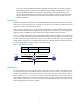
Configuration NAT-PT NOTE: The NAT-PT configuration is available only at the command line interface (CLI). Overview Application scenario Because of the coexistence of IPv4 networks and IPv6 networks, Network Address Translation – Protocol Translation (NAT-PT) was introduced to realize translation between IPv4 and IPv6 addresses. For example, it can enable a host in an IPv6 network to access the FTP server in an IPv4 network. As shown in Figure 28, NAT-PT runs on the device between IPv4 and IPv6 networks.
port numbers so that these IPv6 hosts can share one IPv4 address to accomplish the address translation and save IPv4 addresses. NAT-PT prefix The 96-bit NAT-PT prefix in the IPv6 address prefix format is used in the following cases: • Upon receiving a packet from an IPv6 host to an IPv4 host, the NAT-PT device detects the prefix of the destination IPv6 address in the packet.
Upon receiving a reply packet from the IPv4 host to the IPv6 host, the NAT-PT device swaps the source and destination IPv4 addresses according to the stored mappings and forwards the packet to the IPv6 host. Session initiated by an IPv4 host The NAT-PT implementation process for a session initiated by an IPv4 host is as follows: 1. Determines whether to perform NAT-PT or not.
NAT-PT configuration task list NAT-PT configuration task list on the IPv6 side Complete the following tasks to configure NAT-PT to allow active access from an IPv4 host to an IPv6 host: Task Remarks Enabling NAT-PT Required. Configuring a NAT-PT prefix Required. Configuring IPv4/IPv6 address mappings on the IPv6 side Required. Optional.
Enabling NAT-PT After NAT-PT is enabled on both the IPv4 network interface and the IPv6 network interface, the firewall can implement translation between IPv4 and IPv6 addresses. To enable NAT-PT: Step Command Remarks 1. Enter system view. system-view N/A 2. Enter interface view. interface interface-type interface-number N/A 3. Enable NAT-PT on the interface. natpt enable Disabled by default NOTE: • The natpt enable command enables both NAT-PT and Address Family Translation (AFT).
Step Command 1. Enter system view. system-view 2. Configure a static IPv4/IPv6 address mapping on the IPv6 side.
Step Command Remarks • Associate an IPv6 ACL with an address pool: natpt v6bound dynamic acl6 number acl-number address-group address-group [ no-pat ] • Associate an IPv6 ACL with an Configure a dynamic IPv4/IPv6 address mapping policy on the IPv6 side. 3. interface address: natpt v6bound dynamic acl6 number acl-number interface interface-type interface-number Use one of the commands.
Step 2. Command Configure a static IPv4/IPv6 address mapping on the IPv4 side. natpt v4bound static ipv4-address ipv6-address Configuring a dynamic mapping policy on the IPv4 side A dynamic IPv4/IPv6 address mapping policy on the IPv4 side is that if the source IPv4 address matches a specified ACL, the source IPv4 address is added with a NAT-PT prefix as the translated IPv6 address. To configure a dynamic IPv4/IPv6 mapping policy on the IPv4 side: Step Command 1. Enter system view. system-view 2.
Step Set the Traffic Class field in IPv6 packets translated from IPv4 packets to 0. 2. Command Remarks natpt turn-off traffic-class By default, the value of the Traffic Class field of IPv6 packets is the same as that of the ToS field in corresponding IPv4 packets. Configuring static NAPT-PT mappings of IPv6 servers Generally, a server such as the FTP server, Web server, or Telnet server on an IPv6 network provides services for IPv6 hosts only.
Task Command Remarks Display NAT-PT statistics information. display natpt statistics [ | { begin | exclude | include } regular-expression ] Available in any view Clear all NAT-PT statistics information. reset natpt statistics Available in user view NAT-PT configuration examples Configuring dynamic mapping on the IPv6 side Network requirements As shown in Figure 30, Firewall C with IPv6 address 2001::2/64 on an IPv6 network wants to access Firewall A with IPv4 address 8.0.0.
Configuring Firewall A on the IPv4 side # Configure a static route to subnet 9.0.0.0/24. system-view [FirewallA] ip route-static 9.0.0.0 24 8.0.0.1 Configuring Firewall C on the IPv6 side # Enable IPv6. system-view [FirewallC] ipv6 # Configure a static route to the subnet with the NAT-PT prefix.
Figure 31 Network diagram Configuring Firewall B # Configure interface addresses and enable NAT-PT on the interfaces. system-view [FirewallB] ipv6 [FirewallB] interface GigabitEthernet 0/1 [FirewallB-GigabitEthernet0/1] ip address 8.0.0.1 255.255.255.
Responder: Source IP/Port : 2001::0002/33024 Dest IP/Port : 3001::0005/1 VPN-Instance/VLAN ID/VLL ID: Pro: ICMP(1) App: unknown Start time: 2011-07-20 19:08:44 Root State: ICMP-CLOSED TTL: 10s Zone(in): Zone(out): Received packet(s)(Init): 5 packet(s) 420 byte(s) Received packet(s)(Reply): 5 packet(s) 520 byte(s) Using the ping ipv6 3001::5 command on Firewall C can receive response packets, and you can view the following NAT-PT session information on Firewall B by using the display command.
Configuration ALG ALG overview The application level gateway (ALG) feature is used to process application layer packets. Usually, Network Address Translation (NAT) translates only IP address and port information in packet headers and does not analyze fields in application layer payloads. However, the packet payloads of some protocols may contain IP address or port information, which, if not translated, may cause problems.
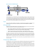
The following describes the FTP operation on an ALG-enabled device. As shown in Figure 32, the host in the outside network accesses the FTP server in the inside network in passive mode through the ALG-enabled device.
Configuring ALG in the web interface By default, the ALG function is enabled for all protocols. From the navigation tree, select Firewall > ALG to enter the page as shown in Figure 33. Figure 33 ALG configuration page • To add selected application protocols, select them in the Optional Application Protocols list and click the << button. Then the protocols will be added to the Selected Application Protocols list.
Figure 34 Network diagram Configuration procedure 1. Enable FTP ALG: By default, the FTP ALG function is enabled, and this step is optional. a. Select Firewall > ALG from the navigation tree. The Application Layer Inspection tab appears, as shown in Figure 35. b. Select ftp in the Optional Application Protocols list and click the << button to add it to the Selected Application Protocols list. c. Click OK. Figure 35 Configuring FTP ALG 2. Configure an ACL: # Create a basic ACL: a.
Figure 36 Adding ACL 2001 # Configure an ACL rule. a. Click the icon for ACL 2001 and then click Add. b. Select Permit as the operation, as shown in Figure 37: c. Click Apply. Figure 37 Adding an ACL rule 3. Configure dynamic NAT and the internal server: # Configure the address pool: a. Select Firewall > NAT Policy > Dynamic NAT from the navigation tree and then click Add in the Address Pool area. b. Add a NAT address pool as shown in Figure 38: Enter 1 in the Index field. Enter 5.5.5.
Figure 38 Adding a NAT address pool # Configure dynamic NAT: a. In the Dynamic NAT area, click Add. b. Configure dynamic NAT as shown in Figure 39: Select GigabitEthernet0/1. Enter 2001 for the ACL field. Select PAT as the address translation. Enter 1 as the address pool index. c. Click Apply. Figure 39 Configuring dynamic NAT # Configure the internal FTP server: a. Select Firewall > NAT > Internal Server from the navigation tree and then click Add in the Internal Server area. b.
Figure 40 Configuring an internal FTP server SIP/H.323 ALG configuration example The H.323 ALG configuration is similar to the SIP ALG configuration. This example describes the SIP ALG configuration. Network requirements As shown in Figure 41, a company uses the private network segment 192.168.1.0/24, and has four public network addresses: 5.5.5.1, 5.5.5.9, 5.5.5.10, and 5.5.5.11. SIP UA 1 is on the internal network and SIP UA 2 is on the external network.
By default, the SIP ALG function is enabled, and this step is optional. a. Select Firewall > ALG from the navigation tree. The Application Layer Inspection tab appears, as shown in Figure 42. b. Select sip in the Optional Application Protocols list and click the << button to add it to the Selected Application Protocols list. c. Click OK. Figure 42 Configuring SIP ALG 2. Configure an ACL: # Create a basic ACL: a. Select Firewall > ACL from the navigation tree and then click Add. b.
# Create an ACL rule: a. Click the icon for ACL 2001 and then click Add. b. Crate an ACL rule as shown in Figure 44: Select Permit as the operation. Select Source IP Address, and enter 192.168.1.0 as the source IP address, and 0.0.0.255 as the source wildcard. c. Click Apply. Figure 44 Configuring an ACL rule to permit packets sourced from 192.168.1.0/24 d. Click Add. e. Select Deny as the operation, as shown in Figure 45. f. Click Apply. Figure 45 Configuring an ACL rule to deny packets 3.
Figure 46 Configuring a NAT address pool # Configure dynamic NAT: a. In the Dynamic NAT area, click Add. b. Configure dynamic NAT as shown in Figure 47: Select GigabitEthernet0/1. Enter 2001 for the ACL field. Select PAT as the address translation. Enter 1 as the address pool index. c. Click Apply. Figure 47 Configuring dynamic NAT NBT ALG configuration example Network requirements As shown in Figure 48, a company using the private network segment 192.168.1.
Figure 48 Network diagram Configuration procedure 1. Enable NBT ALG: By default, the NBT ALG function is enabled, and this step is optional. a. Select Firewall > ALG from the navigation tree. The Application Layer Inspection tab appears, as shown in Figure 49. b. Select nbt in the Optional Application Protocols list and click the << button to add it to the Selected Application Protocols list. c. Click OK. Figure 49 Configuring NBT ALG 2.
Figure 50 Configuring a static address mapping # Configure static NAT for interface GigabitEthernet 0/1: a. In the Interface Static Translation area, click Add. b. Select GigabitEthernet0/1, as shown in Figure 51. c. Click Apply. Figure 51 Configuring interface static translation # Configure the internal WINS server. a. Select Firewall > NAT > Internal Server from the navigation tree and then click Add in the Internal Server area. b.
Figure 52 Configure an internal WINS server d. In the Internal Server area, click Add. e. Configure an interval WINS server, which is similar to the configuration shown in Figure 52. Select GigabitEthernet0/1. Select 17(UDP) as the protocol type, Enter 5.5.5.10 as the external IP address. Enter 138 as the global port. Enter 192.168.1.2 as the internal IP address. Enter 138 as the internal port. f. Click Apply. g. In the Internal Server area, click Add. h.
Enabling ALG at the CLI Step 1. 2. Command Remarks Enter system view. system-view N/A Optional. Enable ALG. alg { all | dns | ftp | gtp | h323 | ils | msn | nbt | pptp | qq | rtsp | sccp | sip | sqlnet | tftp } Enabled for all protocols by default. ALG configuration examples at the CLI The following examples describe only ALG-related configurations, assuming that other required configurations on the server and client have been done.
The H.323 ALG configuration is similar to the SIP ALG configuration. This example describes the SIP ALG configuration. Network requirements As shown in Figure 54, a company uses the private network segment 192.168.1.0/24, and has four public network addresses: 5.5.5.1, 5.5.5.9, 5.5.5.10, and 5.5.5.11. SIP UA 1 is on the internal network and SIP UA 2 is on the external network.
Figure 55 Network diagram Configuration procedure # Configure a static NAT entry. system-view [Firewall] nat static 192.168.1.3 5.5.5.9 # Enable ALG for NBT. [Firewall] alg nbt # Configure NAT. [Firewall] interface GigabitEthernet 0/2 [Firewall-GigabitEthernet0/2] nat outbound static # Configure the internal WINS server. [Firewall-GigabitEthernet0/2] nat server protocol udp global 5.5.5.10 137 inside 192.168.1.2 137 [Firewall-GigabitEthernet0/2] nat server protocol udp global 5.5.5.
Support and other resources Contacting HP For worldwide technical support information, see the HP support website: http://www.hp.
Conventions This section describes the conventions used in this documentation set. Command conventions Convention Description Boldface Bold text represents commands and keywords that you enter literally as shown. Italic Italic text represents arguments that you replace with actual values. [] Square brackets enclose syntax choices (keywords or arguments) that are optional. { x | y | ... } Braces enclose a set of required syntax choices separated by vertical bars, from which you select one.
Network topology icons Represents a generic network device, such as a router, switch, or firewall. Represents a routing-capable device, such as a router or Layer 3 switch. Represents a generic switch, such as a Layer 2 or Layer 3 switch, or a router that supports Layer 2 forwarding and other Layer 2 features. Represents a firewall. Port numbering in examples The port numbers in this document are for illustration only and might be unavailable on your device.
Index ACDENORT A Displaying and maintaining NAT-PT,39 ALG configuration examples at the CLI,57 E ALG configuration examples in the web interface,46 Enabling ALG at the CLI,57 ALG overview,44 N C NAT configuration examples,26 Configuration guidelines,30 NAT configuration task list at the CLI,20 Configuring address translation,21 NAT-PT configuration examples,40 Configuring ALG in the web interface,46 NAT-PT configuration task list,34 Configuring an internal server,24 O Configuring DNS mappi