
R3721-F3210-F3171-HP High-End Firewalls Network Management Configuration Guide-6PW101
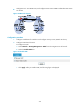
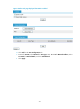
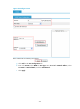
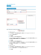
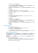

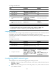
Table Of Contents
- Title Page
- Contents
- Configuring interface management
- Feature and hardware compatibility
- Overview
- Managing interfaces in the web interface
- Managing interfaces at the CLI
- General configuration for Ethernet interfaces and subinterfaces
- Configuring a combo interface
- Configuring basic settings of an Ethernet interface or subinterface
- Shutting down an Ethernet interface or subinterface
- Configuring flow control on an Ethernet interface
- Configuring loopback testing on an Ethernet interface
- Configuring the link mode of an Ethernet interface
- Enabling subinterface rate statistics collection on an Ethernet interface
- Configuring a Layer 2 Ethernet interface or subinterface
- Configuring a Layer 3 Ethernet interface or subinterface
- Configuring a loopback interface
- Configuring the null interface
- Displaying and maintaining loopback and null interfaces
- General configuration for Ethernet interfaces and subinterfaces
- Configuring IPv4 address
- Configuring VLANs
- Configuring the MAC address table
- Configuring MSTP
- Introduction to STP
- Introduction to RSTP
- Introduction to MSTP
- Configuring MSTP in the Web interface
- Configuring MSTP at the CLI
- Spanning tree configuration task list
- Setting the spanning tree mode
- Configuring the root bridge or a secondary root bridge
- Configuring the device priority
- Configuring the maximum hops of an MST region
- Configuring the timeout factor
- Configuring the maximum port rate
- Configuring edge ports
- Configuring path costs of ports
- Configuring the port priority
- Configuring the port link type
- Configuring the mode a port uses to recognize/send MSTP packets
- Enabling the spanning tree feature
- Performing mCheck
- Configuring Digest Snooping
- Configuring No Agreement Check
- Configuring protection functions
- Displaying and maintaining the spanning tree
- Spanning tree configuration example
- Configuration guidelines
- Configuring PPP
- Overview
- Performing general PPP configurations
- Configuring MS-CHAP or MS-CHAP-V2 authentication
- Configuring PPP negotiation
- Enabling the ignoring of next-hop address matching
- Displaying and maintaining PPP
- PPP configuration examples
- Troubleshooting PPP configuration
- Configuring PPPoE
- Configuring Layer 2 forwarding
- Feature and hardware compatibility
- Configuring general Layer 2 forwarding
- Configuring inline Layer 2 forwarding
- Working mechanism
- Configuring inline forwarding in the Web interface
- Forward-type inline forwarding configuration example in the Web interface
- Blackhole-type inline forwarding configuration example in the Web interface
- Configuring inline forwarding at the CLI
- Displaying and maintaining inline Layer 2 forwarding
- Forward-type inline Layer 2 forwarding configuration example at the CLI
- Blackhole-type inline Layer 2 forwarding configuration example at the CLI
- Configuration guidelines
- Viewing frame forwarding statistics
- DHCP overview
- Configuring DHCP server
- Introduction to DHCP server
- Configuring the DHCP server in the web interface
- DHCP server configuration task list
- Enabling DHCP
- Creating a static address pool for the DHCP server
- Creating a dynamic address pool for the DHCP server
- Enabling the DHCP server on an interface
- Display the information of assigned IP addresses
- DHCP server configuration examples
- Static IP address assignment configuration example
- Dynamic IP address assignment configuration example
- Configuring the DHCP server at the CLI
- DHCP server configuration task list
- Configuring an address pool for the DHCP server
- Configuration task list
- Creating a DHCP address pool
- Configuring an address allocation mode for a common address pool
- Configuring dynamic address allocation for an extended address pool
- Configuring a domain name suffix for the client
- Configuring DNS servers for the client
- Configuring WINS servers and NetBIOS node type for the client
- Configuring BIMS server information for the client
- Configuring gateways for the client
- Configuring Option 184 parameters for the client with voice service
- Configuring the TFTP server and bootfile name for the client
- Configuring self-defined DHCP options
- Enabling DHCP
- Enabling the DHCP server on an interface
- Applying an extended address pool on an interface
- Configuring the DHCP server security functions
- Enabling Option 82 handling
- Specifying the threshold for sending trap messages
- Displaying and maintaining the DHCP server
- DHCP server configuration examples
- Static IP address assignment configuration example
- Dynamic IP address assignment configuration example
- Self-defined option configuration example
- Configuring an address pool for the DHCP server
- Troubleshooting DHCP server configuration
- Configuring DHCP relay agent
- Introduction to DHCP relay agent
- Configuring the DHCP relay agent in the web interface
- Configuring the DHCP relay agent at the CLI
- DHCP relay agent configuration task list
- Enabling DHCP
- Enabling offline detection
- Configuring the DHCP relay agent to release an IP address
- Configuring the DHCP relay agent to support Option 82
- Displaying and maintaining the DHCP relay agent
- DHCP relay agent configuration example
- DHCP relay agent Option 82 support configuration example
- Troubleshooting DHCP relay agent configuration
- Configuring DHCP client
- Configuring BOOTP client
- Configuring DNS
- Overview
- Configuring DNS in the web interface
- Static name resolution table configuration task list
- Dynamic domain name resolution configuration task list
- DNS proxy configuration task list
- Configuring static name resolution entries
- Configuring dynamic domain name resolution
- Configuring DNS proxy
- Configuring DNS server addresses
- Configuring domain name suffixes
- Dynamic domain name resolution configuration example
- Configuring DNS at the CLI
- Troubleshooting IPv4 DNS configuration
- Configuring DDNS
- Configuring ARP
- Overview
- Configuring ARP in the web interface
- Configuring ARP at the CLI
- Configuring gratuitous ARP
- Configuring proxy ARP
- Configuring QoS
- Feature and hardware compatibility
- Overview
- Configuring a QoS policy
- Configuring line rate on a port
- QoS configuration examples
- Configuration guidelines
- Configuring traffic policing
- IP routing overview
- Static route configuration
- Feature and hardware compatibility
- Overview
- Configuring a static route in the web interface
- Configuring a static route at the CLI
- Configuring RIP
- Feature and hardware compatibility
- Configuring RIP in the web interface
- Configuring RIP at the CLI
- RIP configuration task list
- Configuring RIP basic functions
- Configuring RIP route control
- Tuning and optimizing RIP networks
- Configuring RIP timers
- Configuring split horizon and poison reverse
- Configuring the maximum number of ECMP routes
- Enabling zero field check on incoming RIPv1 messages
- Enabling source IP address check on incoming RIP updates
- Configuring RIPv2 message authentication
- Specifying a RIP neighbor
- Configuring RIP-to-MIB binding
- Configuring the RIP packet sending rate
- Configuring BFD for RIP
- Displaying and maintaining RIP
- RIP version configuration at the CLI
- Configuring RIP route redistribution at the CLI
- Configuring an additional metric for a RIP interface at the CLI
- Configuring RIP to advertise a summary route at the CLI
- Configuring BFD for RIP (single-hop detection in BFD echo packet mode) at the CLI
- Configuring BFD for RIP (bidirectional detection in BFD control packet mode) at the CLI
- Troubleshooting RIP
- Configuration guidelines
- Configuring OSPF
- Hardware and feature compatibility
- Overview
- Configuring OSPF in the web interface
- Configuring OSPF at the CLI
- OSPF configuration task list
- Enabling OSPF
- Configuring OSPF areas
- Configuring OSPF network types
- Configuring OSPF route control
- Configuration prerequisites
- Configuring OSPF route summarization
- Configuring ABR Type-3 LSA filtering
- Configuring an OSPF cost for an interface
- Configuring the maximum number of OSPF routes
- Configuring the maximum number of ECMP routes
- Configuring OSPF preference
- Configuring OSPF route redistribution
- Advertising a host route
- Tuning and optimizing OSPF networks
- Configuration prerequisites
- Configuring OSPF packet timers
- Specifying LSA transmission delay
- Specifying SPF calculation interval
- Specifying the LSA arrival interval
- Specifying the LSA generation interval
- Disabling interfaces from receiving and sending OSPF packets
- Configuring stub routers
- Configuring OSPF authentication
- Adding the interface MTU into DD packets
- Configuring the maximum number of external LSAs in LSDB
- Enabling compatibility with RFC 1583
- Logging neighbor state changes
- Configuring OSPF network management
- Enabling message logging
- Enabling the advertisement and reception of opaque LSAs
- Configuring OSPF to give priority to receiving and processing hello packets
- Configuring the LSU transmit rate
- Enabling OSPF ISPF
- Configuring BFD for OSPF
- Displaying and maintaining OSPF
- Configuring OSPF basic functions at the CLI
- Configuring OSPF route redistribution at the CLI
- Configuring OSPF to advertise a summary route at the CLI
- Configuring an OSPF stub area at the CLI
- Configuring an OSPF NSSA area at the CLI
- Configuring OSPF DR election at the CLI
- Configuring OSPF virtual links at the CLI
- Configuring route filtering at the CLI
- Configuring BFD for OSPF at the CLI
- Troubleshooting OSPF configuration
- Configuration guidelines
- Configuing IPv6 BGP
- Hardware and feature compatibility
- Overview
- Configuring BGP in the web interface
- Configuring BGP at the CLI
- BGP configuration task list
- Configuring BGP basic functions
- Controlling route generation
- Controlling route distribution and reception
- Configuration prerequisites
- Configuring BGP route summarization
- Advertising a default route to a peer or peer group
- Configuring BGP route distribution/reception filtering policies
- Enabling BGP and IGP route synchronization
- Limiting prefixes received from a peer/peer group
- Configuring BGP route dampening
- Configuring a shortcut route
- Configuring BGP route attributes
- Tuning and optimizing BGP networks
- Configuration prerequisites
- Configuring the BGP keepalive interval and holdtime
- Configuring the interval for sending the same update
- Configuring BGP soft-reset
- Enabling the BGP ORF capability
- Enabling 4-byte AS number suppression
- Enabling quick EBGP session reestablishment
- Enabling MD5 authentication for TCP connections
- Configuring BGP load balancing
- Forbidding session establishment with a peer or peer group
- Configuring a large scale BGP network
- Configuring BGP GR
- Enabling Trap
- Enabling logging of peer state changes
- Configuring BFD for BGP
- Displaying and maintaining BGP
- BGP basic configuration at the CLI
- BGP and IGP synchronization configuration at the CLI
- BGP load balancing configuration at the CLI
- BGP community configuration at the CLI
- BGP confederation configuration at the CLI
- BGP path selection configuration at the CLI
- BFD for BGP configuration example at the CLI
- Troubleshooting BGP
- Configuring IS-IS
- Feature and hardware compatibility
- IS-IS overview
- IS-IS configuration task list
- Configuring IS-IS basic functions
- Configuring IS-IS routing information control
- Tuning and optimizing IS-IS networks
- Configuration prerequisites
- Specifying intervals for sending IS-IS hello and CSNP packets
- Specifying the IS-IS hello multiplier
- Configuring a DIS priority for an interface
- Disabling an interface from sending/receiving IS-IS packets
- Enabling an interface to send small hello packets
- Configuring LSP parameters
- Configuring SPF parameters
- Assigning a high priority to an IS-IS IP prefix
- Setting the LSDB overload bit
- Configuring system ID to host name mappings
- Enabling the logging of neighbor state changes
- Enhancing IS-IS network security
- Enabling IS-IS SNMP trap
- Binding an IS-IS process with MIBs
- Displaying and maintaining IS-IS
- IS-IS configuration examples
- Configuring load sharing
- Displaying the routing table
- Configuring policy-based routing
- Overview
- Configuring PBR in the web interface
- Configuring PBR at the CLI
- Defining a policy
- Configuring local PBR
- Configuring interface PBR
- Displaying and maintaining PBR configuration
- Configuring local PBR based on packet type at the CLI
- Configuring interface PBR based on packet type at the CLI
- Configuring interface PBR based on packet length at the CLI
- Configuring local PBR to specify outgoing interface and next hop at the CLI
- Configuration guidelines
- Multicast overview
- Configuring multicast routing and forwarding
- Configuring multicast routing and forwarding in the Web interface
- Configuring multicast routing and forwarding at the CLI
- Multicast routing and forwarding configuration examples at the CLI
- Troubleshooting multicast static route failure
- Configuring IGMP
- Configuring IGMP in the Web interface
- IGMP configuration example in the Web interface
- Configuring IGMP at the CLI
- IGMP configuration examples at the CLI
- Troubleshooting IGMP
- Configuring PIM
- Configuring PIM in the Web interface
- PIM configuration example in the Web interface
- Configuring PIM at the CLI
- PIM configuration examples at the CLI
- Troubleshooting PIM
- Configuring MSDP
- MSDP configuration task list
- Configuring basic functions of MSDP
- Configuring an MSDP peer connection
- Configuring SA messages related parameters
- Displaying and maintaining MSDP
- MSDP configuration examples
- Troubleshooting MSDP
- Configuring IPv6 basics
- Overview
- IPv6 basics configuration task list
- Configuring basic IPv6 functions
- Configuring IPv6 ND
- Configuring path MTU discovery
- Configuring IPv6 TCP properties
- Configuring IPv6 FIB load sharing
- Configuring ICMPv6 packet sending
- Displaying and maintaining IPv6 basics configuration
- IPv6 basics configuration example
- Troubleshooting IPv6 basics configuration
- DHCPv6 overview
- Configuring the DHCPv6 server
- Configuring the DHCPv6 relay agent
- Configuring the DHCPv6 client
- Configuring IPv6 DNS
- Configuring IPv6 static routing
- RIPng configuration
- OSPFv3 configuration
- Feature and hardware compatibility
- Introduction to OSPFv3
- OSPFv3 configuration task list
- Enabling OSPFv3
- Configuring OSPFv3 area parameters
- Configuring OSPFv3 network types
- Configuring OSPFv3 routing information control
- Tuning and optimizing OSPFv3 networks
- Configuring BFD for OSPFv3
- Applying IPsec policies for OSPFv3
- Displaying and maintaining OSPFv3
- OSPFv3 configuration examples
- Troubleshooting OSPFv3 configuration
- IPv6 BGP configuration
- Feature and hardware compatibility
- IPv6 BGP overview
- IPv6 BGP configuration task list
- Configuring IPv6 BGP basic functions
- Prerequisites
- Specifying an IPv6 BGP peer
- Injecting a local IPv6 route
- Configuring a preferred value for routes from a peer/peer group
- Specifying the source interface for establishing TCP connections
- Allowing the establishment of a non-direct eBGP connection
- Configuring a description for an IPv6 peer/peer group
- Disabling session establishment to an IPv6 peer/peer group
- Logging IPv6 peer/peer group state changes
- Controlling route distribution and reception
- Configuring IPv6 BGP route attributes
- Tuning and optimizing IPv6 BGP networks
- Configuration prerequisites
- Configuring IPv6 BGP timers
- Configuring IPv6 BGP soft reset
- Enabling the IPv6 BGP ORF capability
- Enabling 4-byte AS number suppression
- Configuring the maximum number of load-balanced routes
- Enabling MD5 authentication for TCP connections
- Applying an IPsec policy to an IPv6 BGP peer or peer group
- Configuring a large scale IPv6 BGP network
- Configuring BFD for IPv6 BGP
- Displaying and maintaining IPv6 BGP
- IPv6 BGP configuration examples
- Troubleshooting IPv6 BGP configuration
- Configuring IPv6 IS-IS
- Displaying the IPv6 routing table
- Configuring IPv6 policy-based routing
- Configuring IPv6 multicast routing and forwarding
- Configuring IPv6 PIM
- Introduction to IPv6 PIM
- Configuring IPv6 PIM-SM
- Configuring IPv6 PIM-SSM
- Configuring IPv6 PIM common features
- Displaying and maintaining IPv6 PIM
- IPv6 PIM configuration examples
- Troubleshooting IPv6 PIM
- Configuring MLD
- Overview
- MLD configuration task list
- Configuring basic functions of MLD
- Adjusting MLD performance
- Configuring MLD SSM mapping
- Configuring MLD proxying
- Displaying and maintaining MLD
- MLD configuration examples
- Troubleshooting MLD
- Routing policy configuration
- Configuring SSL
- Support and other resources
- Index
374
d. Click Add on the Area Configuration tab.
e. Enter 1 for Area ID, Select NSSA for Area Type, enter 10.2.1.0 for Network Address, select
0.0.0.255 for Network Mask, and click Add Network.
f. Enter 10.4.1.0 for Network Address, and select 0.0.0.255 for Network Mask, and click Add
Network.
g. Click Apply.
h. Select Network > Static Route from the navigation tree and click Add.
i. Enter 3.2.1.1 as the destination IP address, select 255.255.255.0 from the mask list, and enter
10.4.1.2 as the nexthop.
j. Click Apply.
# Configure Device C.
a. Select Network > Routing Management > OSPF from the navigation tree of Device C.
b. Select the Enable OSPF box.
c. Click Apply.
d. Click Add on the Area Configuration tab.
e. Enter 2 for Area ID, select Normal for Area Type, enter 10.3.1.0 for Network Address, select
0.0.0.255 for Network Mask, and click Add Network.
f. Enter 10.5.1.0 for Network Address, and select 0.0.0.255 for Network Mask, and click Add
Network.
g. Click Apply.
Verifying the configuration
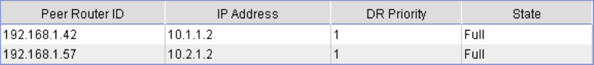
1. Display neighbor information of Firewall:
a. Select Network > Routing Management > OSPF from the navigation tree.
b. Click Show Peer in the Show Information field.
A neighbor in Full state is displayed in area 0 and area 1 respectively. (192.168.1.42 is the
router ID of Device A, and 192.168.1.57 is the router ID of Device B.)
Figure 261 OSPF configuration result I
2. Display the routing table of Firewall.
Select Network > Routing Management > Routing Info from the navigation tree. The OSPF routes
3.2.1.0/24, 10.3.1.0/24, 10.4.1.0/24 and 10.5.1.0/24 that are learned after OSPF is
enabled are displayed in the routing table.