
R3721-F3210-F3171-HP High-End Firewalls Network Management Configuration Guide-6PW101
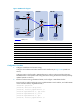
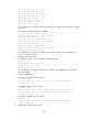
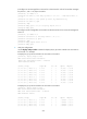
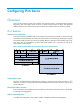
Table Of Contents
- Title Page
- Contents
- Configuring interface management
- Feature and hardware compatibility
- Overview
- Managing interfaces in the web interface
- Managing interfaces at the CLI
- General configuration for Ethernet interfaces and subinterfaces
- Configuring a combo interface
- Configuring basic settings of an Ethernet interface or subinterface
- Shutting down an Ethernet interface or subinterface
- Configuring flow control on an Ethernet interface
- Configuring loopback testing on an Ethernet interface
- Configuring the link mode of an Ethernet interface
- Enabling subinterface rate statistics collection on an Ethernet interface
- Configuring a Layer 2 Ethernet interface or subinterface
- Configuring a Layer 3 Ethernet interface or subinterface
- Configuring a loopback interface
- Configuring the null interface
- Displaying and maintaining loopback and null interfaces
- General configuration for Ethernet interfaces and subinterfaces
- Configuring IPv4 address
- Configuring VLANs
- Configuring the MAC address table
- Configuring MSTP
- Introduction to STP
- Introduction to RSTP
- Introduction to MSTP
- Configuring MSTP in the Web interface
- Configuring MSTP at the CLI
- Spanning tree configuration task list
- Setting the spanning tree mode
- Configuring the root bridge or a secondary root bridge
- Configuring the device priority
- Configuring the maximum hops of an MST region
- Configuring the timeout factor
- Configuring the maximum port rate
- Configuring edge ports
- Configuring path costs of ports
- Configuring the port priority
- Configuring the port link type
- Configuring the mode a port uses to recognize/send MSTP packets
- Enabling the spanning tree feature
- Performing mCheck
- Configuring Digest Snooping
- Configuring No Agreement Check
- Configuring protection functions
- Displaying and maintaining the spanning tree
- Spanning tree configuration example
- Configuration guidelines
- Configuring PPP
- Overview
- Performing general PPP configurations
- Configuring MS-CHAP or MS-CHAP-V2 authentication
- Configuring PPP negotiation
- Enabling the ignoring of next-hop address matching
- Displaying and maintaining PPP
- PPP configuration examples
- Troubleshooting PPP configuration
- Configuring PPPoE
- Configuring Layer 2 forwarding
- Feature and hardware compatibility
- Configuring general Layer 2 forwarding
- Configuring inline Layer 2 forwarding
- Working mechanism
- Configuring inline forwarding in the Web interface
- Forward-type inline forwarding configuration example in the Web interface
- Blackhole-type inline forwarding configuration example in the Web interface
- Configuring inline forwarding at the CLI
- Displaying and maintaining inline Layer 2 forwarding
- Forward-type inline Layer 2 forwarding configuration example at the CLI
- Blackhole-type inline Layer 2 forwarding configuration example at the CLI
- Configuration guidelines
- Viewing frame forwarding statistics
- DHCP overview
- Configuring DHCP server
- Introduction to DHCP server
- Configuring the DHCP server in the web interface
- DHCP server configuration task list
- Enabling DHCP
- Creating a static address pool for the DHCP server
- Creating a dynamic address pool for the DHCP server
- Enabling the DHCP server on an interface
- Display the information of assigned IP addresses
- DHCP server configuration examples
- Static IP address assignment configuration example
- Dynamic IP address assignment configuration example
- Configuring the DHCP server at the CLI
- DHCP server configuration task list
- Configuring an address pool for the DHCP server
- Configuration task list
- Creating a DHCP address pool
- Configuring an address allocation mode for a common address pool
- Configuring dynamic address allocation for an extended address pool
- Configuring a domain name suffix for the client
- Configuring DNS servers for the client
- Configuring WINS servers and NetBIOS node type for the client
- Configuring BIMS server information for the client
- Configuring gateways for the client
- Configuring Option 184 parameters for the client with voice service
- Configuring the TFTP server and bootfile name for the client
- Configuring self-defined DHCP options
- Enabling DHCP
- Enabling the DHCP server on an interface
- Applying an extended address pool on an interface
- Configuring the DHCP server security functions
- Enabling Option 82 handling
- Specifying the threshold for sending trap messages
- Displaying and maintaining the DHCP server
- DHCP server configuration examples
- Static IP address assignment configuration example
- Dynamic IP address assignment configuration example
- Self-defined option configuration example
- Configuring an address pool for the DHCP server
- Troubleshooting DHCP server configuration
- Configuring DHCP relay agent
- Introduction to DHCP relay agent
- Configuring the DHCP relay agent in the web interface
- Configuring the DHCP relay agent at the CLI
- DHCP relay agent configuration task list
- Enabling DHCP
- Enabling offline detection
- Configuring the DHCP relay agent to release an IP address
- Configuring the DHCP relay agent to support Option 82
- Displaying and maintaining the DHCP relay agent
- DHCP relay agent configuration example
- DHCP relay agent Option 82 support configuration example
- Troubleshooting DHCP relay agent configuration
- Configuring DHCP client
- Configuring BOOTP client
- Configuring DNS
- Overview
- Configuring DNS in the web interface
- Static name resolution table configuration task list
- Dynamic domain name resolution configuration task list
- DNS proxy configuration task list
- Configuring static name resolution entries
- Configuring dynamic domain name resolution
- Configuring DNS proxy
- Configuring DNS server addresses
- Configuring domain name suffixes
- Dynamic domain name resolution configuration example
- Configuring DNS at the CLI
- Troubleshooting IPv4 DNS configuration
- Configuring DDNS
- Configuring ARP
- Overview
- Configuring ARP in the web interface
- Configuring ARP at the CLI
- Configuring gratuitous ARP
- Configuring proxy ARP
- Configuring QoS
- Feature and hardware compatibility
- Overview
- Configuring a QoS policy
- Configuring line rate on a port
- QoS configuration examples
- Configuration guidelines
- Configuring traffic policing
- IP routing overview
- Static route configuration
- Feature and hardware compatibility
- Overview
- Configuring a static route in the web interface
- Configuring a static route at the CLI
- Configuring RIP
- Feature and hardware compatibility
- Configuring RIP in the web interface
- Configuring RIP at the CLI
- RIP configuration task list
- Configuring RIP basic functions
- Configuring RIP route control
- Tuning and optimizing RIP networks
- Configuring RIP timers
- Configuring split horizon and poison reverse
- Configuring the maximum number of ECMP routes
- Enabling zero field check on incoming RIPv1 messages
- Enabling source IP address check on incoming RIP updates
- Configuring RIPv2 message authentication
- Specifying a RIP neighbor
- Configuring RIP-to-MIB binding
- Configuring the RIP packet sending rate
- Configuring BFD for RIP
- Displaying and maintaining RIP
- RIP version configuration at the CLI
- Configuring RIP route redistribution at the CLI
- Configuring an additional metric for a RIP interface at the CLI
- Configuring RIP to advertise a summary route at the CLI
- Configuring BFD for RIP (single-hop detection in BFD echo packet mode) at the CLI
- Configuring BFD for RIP (bidirectional detection in BFD control packet mode) at the CLI
- Troubleshooting RIP
- Configuration guidelines
- Configuring OSPF
- Hardware and feature compatibility
- Overview
- Configuring OSPF in the web interface
- Configuring OSPF at the CLI
- OSPF configuration task list
- Enabling OSPF
- Configuring OSPF areas
- Configuring OSPF network types
- Configuring OSPF route control
- Configuration prerequisites
- Configuring OSPF route summarization
- Configuring ABR Type-3 LSA filtering
- Configuring an OSPF cost for an interface
- Configuring the maximum number of OSPF routes
- Configuring the maximum number of ECMP routes
- Configuring OSPF preference
- Configuring OSPF route redistribution
- Advertising a host route
- Tuning and optimizing OSPF networks
- Configuration prerequisites
- Configuring OSPF packet timers
- Specifying LSA transmission delay
- Specifying SPF calculation interval
- Specifying the LSA arrival interval
- Specifying the LSA generation interval
- Disabling interfaces from receiving and sending OSPF packets
- Configuring stub routers
- Configuring OSPF authentication
- Adding the interface MTU into DD packets
- Configuring the maximum number of external LSAs in LSDB
- Enabling compatibility with RFC 1583
- Logging neighbor state changes
- Configuring OSPF network management
- Enabling message logging
- Enabling the advertisement and reception of opaque LSAs
- Configuring OSPF to give priority to receiving and processing hello packets
- Configuring the LSU transmit rate
- Enabling OSPF ISPF
- Configuring BFD for OSPF
- Displaying and maintaining OSPF
- Configuring OSPF basic functions at the CLI
- Configuring OSPF route redistribution at the CLI
- Configuring OSPF to advertise a summary route at the CLI
- Configuring an OSPF stub area at the CLI
- Configuring an OSPF NSSA area at the CLI
- Configuring OSPF DR election at the CLI
- Configuring OSPF virtual links at the CLI
- Configuring route filtering at the CLI
- Configuring BFD for OSPF at the CLI
- Troubleshooting OSPF configuration
- Configuration guidelines
- Configuing IPv6 BGP
- Hardware and feature compatibility
- Overview
- Configuring BGP in the web interface
- Configuring BGP at the CLI
- BGP configuration task list
- Configuring BGP basic functions
- Controlling route generation
- Controlling route distribution and reception
- Configuration prerequisites
- Configuring BGP route summarization
- Advertising a default route to a peer or peer group
- Configuring BGP route distribution/reception filtering policies
- Enabling BGP and IGP route synchronization
- Limiting prefixes received from a peer/peer group
- Configuring BGP route dampening
- Configuring a shortcut route
- Configuring BGP route attributes
- Tuning and optimizing BGP networks
- Configuration prerequisites
- Configuring the BGP keepalive interval and holdtime
- Configuring the interval for sending the same update
- Configuring BGP soft-reset
- Enabling the BGP ORF capability
- Enabling 4-byte AS number suppression
- Enabling quick EBGP session reestablishment
- Enabling MD5 authentication for TCP connections
- Configuring BGP load balancing
- Forbidding session establishment with a peer or peer group
- Configuring a large scale BGP network
- Configuring BGP GR
- Enabling Trap
- Enabling logging of peer state changes
- Configuring BFD for BGP
- Displaying and maintaining BGP
- BGP basic configuration at the CLI
- BGP and IGP synchronization configuration at the CLI
- BGP load balancing configuration at the CLI
- BGP community configuration at the CLI
- BGP confederation configuration at the CLI
- BGP path selection configuration at the CLI
- BFD for BGP configuration example at the CLI
- Troubleshooting BGP
- Configuring IS-IS
- Feature and hardware compatibility
- IS-IS overview
- IS-IS configuration task list
- Configuring IS-IS basic functions
- Configuring IS-IS routing information control
- Tuning and optimizing IS-IS networks
- Configuration prerequisites
- Specifying intervals for sending IS-IS hello and CSNP packets
- Specifying the IS-IS hello multiplier
- Configuring a DIS priority for an interface
- Disabling an interface from sending/receiving IS-IS packets
- Enabling an interface to send small hello packets
- Configuring LSP parameters
- Configuring SPF parameters
- Assigning a high priority to an IS-IS IP prefix
- Setting the LSDB overload bit
- Configuring system ID to host name mappings
- Enabling the logging of neighbor state changes
- Enhancing IS-IS network security
- Enabling IS-IS SNMP trap
- Binding an IS-IS process with MIBs
- Displaying and maintaining IS-IS
- IS-IS configuration examples
- Configuring load sharing
- Displaying the routing table
- Configuring policy-based routing
- Overview
- Configuring PBR in the web interface
- Configuring PBR at the CLI
- Defining a policy
- Configuring local PBR
- Configuring interface PBR
- Displaying and maintaining PBR configuration
- Configuring local PBR based on packet type at the CLI
- Configuring interface PBR based on packet type at the CLI
- Configuring interface PBR based on packet length at the CLI
- Configuring local PBR to specify outgoing interface and next hop at the CLI
- Configuration guidelines
- Multicast overview
- Configuring multicast routing and forwarding
- Configuring multicast routing and forwarding in the Web interface
- Configuring multicast routing and forwarding at the CLI
- Multicast routing and forwarding configuration examples at the CLI
- Troubleshooting multicast static route failure
- Configuring IGMP
- Configuring IGMP in the Web interface
- IGMP configuration example in the Web interface
- Configuring IGMP at the CLI
- IGMP configuration examples at the CLI
- Troubleshooting IGMP
- Configuring PIM
- Configuring PIM in the Web interface
- PIM configuration example in the Web interface
- Configuring PIM at the CLI
- PIM configuration examples at the CLI
- Troubleshooting PIM
- Configuring MSDP
- MSDP configuration task list
- Configuring basic functions of MSDP
- Configuring an MSDP peer connection
- Configuring SA messages related parameters
- Displaying and maintaining MSDP
- MSDP configuration examples
- Troubleshooting MSDP
- Configuring IPv6 basics
- Overview
- IPv6 basics configuration task list
- Configuring basic IPv6 functions
- Configuring IPv6 ND
- Configuring path MTU discovery
- Configuring IPv6 TCP properties
- Configuring IPv6 FIB load sharing
- Configuring ICMPv6 packet sending
- Displaying and maintaining IPv6 basics configuration
- IPv6 basics configuration example
- Troubleshooting IPv6 basics configuration
- DHCPv6 overview
- Configuring the DHCPv6 server
- Configuring the DHCPv6 relay agent
- Configuring the DHCPv6 client
- Configuring IPv6 DNS
- Configuring IPv6 static routing
- RIPng configuration
- OSPFv3 configuration
- Feature and hardware compatibility
- Introduction to OSPFv3
- OSPFv3 configuration task list
- Enabling OSPFv3
- Configuring OSPFv3 area parameters
- Configuring OSPFv3 network types
- Configuring OSPFv3 routing information control
- Tuning and optimizing OSPFv3 networks
- Configuring BFD for OSPFv3
- Applying IPsec policies for OSPFv3
- Displaying and maintaining OSPFv3
- OSPFv3 configuration examples
- Troubleshooting OSPFv3 configuration
- IPv6 BGP configuration
- Feature and hardware compatibility
- IPv6 BGP overview
- IPv6 BGP configuration task list
- Configuring IPv6 BGP basic functions
- Prerequisites
- Specifying an IPv6 BGP peer
- Injecting a local IPv6 route
- Configuring a preferred value for routes from a peer/peer group
- Specifying the source interface for establishing TCP connections
- Allowing the establishment of a non-direct eBGP connection
- Configuring a description for an IPv6 peer/peer group
- Disabling session establishment to an IPv6 peer/peer group
- Logging IPv6 peer/peer group state changes
- Controlling route distribution and reception
- Configuring IPv6 BGP route attributes
- Tuning and optimizing IPv6 BGP networks
- Configuration prerequisites
- Configuring IPv6 BGP timers
- Configuring IPv6 BGP soft reset
- Enabling the IPv6 BGP ORF capability
- Enabling 4-byte AS number suppression
- Configuring the maximum number of load-balanced routes
- Enabling MD5 authentication for TCP connections
- Applying an IPsec policy to an IPv6 BGP peer or peer group
- Configuring a large scale IPv6 BGP network
- Configuring BFD for IPv6 BGP
- Displaying and maintaining IPv6 BGP
- IPv6 BGP configuration examples
- Troubleshooting IPv6 BGP configuration
- Configuring IPv6 IS-IS
- Displaying the IPv6 routing table
- Configuring IPv6 policy-based routing
- Configuring IPv6 multicast routing and forwarding
- Configuring IPv6 PIM
- Introduction to IPv6 PIM
- Configuring IPv6 PIM-SM
- Configuring IPv6 PIM-SSM
- Configuring IPv6 PIM common features
- Displaying and maintaining IPv6 PIM
- IPv6 PIM configuration examples
- Troubleshooting IPv6 PIM
- Configuring MLD
- Overview
- MLD configuration task list
- Configuring basic functions of MLD
- Adjusting MLD performance
- Configuring MLD SSM mapping
- Configuring MLD proxying
- Displaying and maintaining MLD
- MLD configuration examples
- Troubleshooting MLD
- Routing policy configuration
- Configuring SSL
- Support and other resources
- Index
653
Figure 348 Network diagram
Device Interface IP address
Device
Interface IP address
Source 1 — 10.110.3.100/24 Firewall C GE0/1 10.110.4.1/24
Source 2 — 10.110.6.100/24
GE0/2 10.110.5.1/24
Firewall A GE0/1 10.110.1.1/24
GE0/3 192.168.1.2/24
GE0/2 10.110.2.1/24 GE0/4 192.168.2.2/24
GE0/3 192.168.1.1/24
Loop0 2.2.2.2/32
Loop0 1.1.1.1/32
Firewall D
GE0/1 10.110.6.1/24
Firewall B GE0/1 10.110.3.1/24 GE0/2 10.110.7.1/24
GE0/2 10.110.2.2/24
GE0/3 10.110.5.2/24
GE0/3 192.168.2.1/24
Loop0 3.3.3.3/32
Configuration Procedure
1. Configure IP addresses and unicast routing:
Configure the IP address and subnet mask for each interface as per Figure 348. (Details not
shown.)
Configure OS
PF on the firewalls in PIM-SM domains to make sure the network-layer between
PIM-SM domains is interoperable and routing information among the firewalls can be dynamically
updated. (Details not shown.)
2. Enable IP multicast routing, PIM-SM and IGMP, and configure a PIM domain border:
# On Firewall A, enable IP multicast routing, enable PIM-SM on each interface, and enable IGMP
on the host-side interface, GigabitEthernet 0/1.
<FirewallA> system-view
[FirewallA] multicast routing-enable
[FirewallA] interface gigabitethernet 0/1
[FirewallA-GigabitEthernet0/1] igmp enable
[FirewallA-GigabitEthernet0/1] pim sm
[FirewallA-GigabitEthernet0/1] quit
[FirewallA] interface gigabitethernet 0/2
MSDP peers
PIM-SM 1 PIM-SM 2 PIM-SM 3
Loop0
Loop0
Source 1
Source 2
Receiver
Host B
Receiver
Host C
Receiver
Host A
GE0/1
GE0/1
GE0/1 GE0/2
GE0/2
GE0/2
GE
0
/
3
GE
0
/
3
GE
0
/
3
G
E
0
/
4
GE0/2
GE0/3
GE0/1
Firewall A
Firewall C
Firewall D
Firewall B