HP High-End Firewalls System Management and Maintenance Configuration Guide Part number: 5998-2654 Software version: F1000-A-EI&F1000-S-EI: R3721 F5000: F3210 F1000-E: F3171 Firewall module: F3171 Document version: 6PW101-20120719
Legal and notice information © Copyright 2012 Hewlett-Packard Development Company, L.P. No part of this documentation may be reproduced or transmitted in any form or by any means without prior written consent of Hewlett-Packard Development Company, L.P. The information contained herein is subject to change without notice.
Contents Device information ······················································································································································· 1 Displaying device information ········································································································································· 1 Device info ····················································································································································
Displaying the current working directory ············································································································ 23 Changing the current working directory ············································································································· 23 Creating a directory ·············································································································································· 24 Removing a directory ···················
System information levels ····································································································································· 54 Output channels and destinations ······················································································································· 55 Outputting system information by source module ······························································································ 56 Default output rules of system information ·····
NTP for VPNs ······················································································································································· 100 NTP configuration task list ··········································································································································· 101 Configuring the NTP operation modes ······················································································································ 101 Configuratio
Displaying and maintaining SNMP ··························································································································· 136 SNMP configuration examples ··································································································································· 137 SNMPv1/SNMPv2c configuration example ···································································································· 137 SNMPv3 configuration example··················
Configuration task list ········································································································································· 179 Creating a virtual device ···································································································································· 179 Setting the upper limit of sessions for a virtual device ···················································································· 180 Adding an interface to a virtual devi
Index ········································································································································································ 216 vii
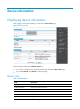
Device information Displaying device information After logging in to the Web interface, you will enter the Device Info page. Figure 1 Device overview Select the refresh mode from the Refresh Period list. • If you select a specific period, the system periodically refreshes the Device Info page. • If you select Manual, click Refresh to refresh the page. Device info Table 1 Field description Field Description Device Name Display the device name. Product Information Display the product information.
Field Description Hardware Version Display the hardware version of the device. Bootrom Version Display the Boot ROM version of the device. Running Time Display the running time after the latest boot of the device. System resource state Table 2 Field description Field Description CPU Usage Display the real-time CPU usage. Memory Usage Display the real-time memory usage. Temperature Display the temperature of the device.
Field Description Description Display the contents of the system logs. NOTE: To know more information about system operation logs, click the More hyperlink in the Recent System Logs area to enter the log Report > Report > System Log page to view the logs. For more information, see "Managing logs.
Using ping, tracert, and system debugging Use the ping, tracert, and system debugging utilities to test network connectivity and identify network problems. The term "router "in this document refers to both routers and Layer 3 firewalls. Ping The ping utility sends ICMP echo requests (ECHO-REQUEST) to the destination device. Upon receiving the requests, the destination device responds with ICMP echo replies (ECHO-REPLY) to the source device.
Figure 2 Page for executing the ping operation 2. Enter the IP address or the host name of the destination device in the field. 3. Click Start. The Summary box displays the ping operation result.
Executing the ping operation at the CLI Task Command Remarks • For IPv4 networks: Test the network connectivity to an IP address.
3. The source device sends a packet with a TTL value of 2 to the destination device. 4. The second hop (Device C) responds with a TTL-expired ICMP error message, which gives the source device the address of the second Layer 3 device (1.1.2.2). 5. The process continues until the packet sent by the source device reaches the ultimate destination device. Because no application uses the destination port specified in the packet.
3. Click Start. The Summary box displays the tracert operation result. Figure 6 Tracert operation result Executing the tracert operation at the CLI Prerequisites • Enable sending of ICMP timeout packets on the intermediate devices (the device between the source and destination devices). If the intermediate devices are HP devices, execute the ip ttl-expires enable command. • Enable sending of ICMP destination unreachable packets on the destination device.
Debugging information control switches The following two switches control the debugging information output: • Protocol debugging switch—Controls protocol-specific debugging information. • Screen output switch—Controls whether to display the debugging information on a certain screen. As shown in Figure 7, assume that the device can provide debugging for the three modules 1, 2, and 3.
Step Enable the terminal display of debugging information. 2. Command Remarks terminal debugging By default, terminal display of debugging information is disabled. Available in user view. 3. 4. Enable debugging for a specified module. debugging { all [ timeout time ] | module-name [ option ] } Display the enabled debugging functions.
Reply from 1.1.2.2: bytes=56 Sequence=4 ttl=254 time=1 ms Reply from 1.1.2.2: bytes=56 Sequence=5 ttl=254 time=1 ms --- 1.1.2.2 ping statistics --5 packet(s) transmitted 5 packet(s) received 0.00% packet loss round-trip min/avg/max = 1/41/205 ms # Get detailed information about routes from Firewall to Device B. ping -r 1.1.2.2 PING 1.1.2.2: 56 data bytes, press CTRL_C to break Reply from 1.1.2.2: bytes=56 Sequence=1 ttl=254 time=53 ms Record Route: 1.1.2.1 1.1.2.2 1.1.1.2 1.1.1.1 Reply from 1.
1. The source device (Firewall) sends an ICMP echo request with the RR option being empty to the destination device (Device B). 2. The intermediate device (Device A) adds the IP address of its outbound interface (1.1.2.1) to the RR option of the ICMP echo request, and forwards the packet. 3. Upon receiving the request, the destination device copies the RR option in the request and adds the IP address of its outbound interface (1.1.2.2) to the RR option.
# Locate the failed nodes on Firewall. tracert 1.1.2.2 traceroute to 1.1.2.2(1.1.2.2) 30 hops max,40 bytes packet, press CTRL_C to bre ak 1 1.1.1.2 14 ms 10 ms 20 ms 2 * * * 3 * * * 4 * * * 5 The output shows that Firewall and Device B cannot reach other, Firewall and Device A can reach each other, and an error occurred on the connection between Device A and Device B. 3.
Configuring IP performance optimization Enabling forwarding of directed broadcasts to a directly connected network Directed broadcast packets are broadcast on a specific network. In the destination IP address of a directed broadcast, the network ID identifies the target network, and the host ID is made up of all ones. If a device is allowed to forward directed broadcasts to a directly connected network, hackers may mount attacks to the network.
Figure 10 Network diagram Configuration procedure 1. Configure Firewall: # Configure IP addresses for GigabitEthernet 0/1 and GigabitEthernet 0/2. [Firewall] interface gigabitethernet 0/1 [Firewall-GigabitEthernet0/1] ip address 1.1.1.2 24 [Firewall-GigabitEthernet0/1] quit [Firewall] interface gigabitethernet 0/2 [Firewall-GigabitEthernet0/2] ip address 2.2.2.2 24 # Enable GigabitEthernet 0/2 to forward directed broadcasts. [Firewall-GigabitEthernet0/2] ip forward-broadcast 2.
Step 3. Command Configure the TCP MSS of the interface. tcp mss value Remarks Optional. The TCP MSS is 1460 bytes by default. NOTE: • This configuration takes effect only on TCP connections that are established after the configuration rather than the TCP connections that already exist. • This configuration is effective only on IP packets. Configuring TCP path MTU discovery TCP path MTU discovery (in RFC 1191) discovers the path MTU between the source and destination ends of a TCP connection.
Step Command Remarks 1. Enter system view. system-view N/A 2. Enable TCP path MTU discovery. tcp path-mtu-discovery [ aging minutes | no-aging ] Optional. Disabled by default. CAUTION: All the devices on the TCP path must be enabled to send ICMP error messages by using the ip unreachables enable command. Configuring the TCP send/receive buffer size Step Command Remarks 1. Enter system view. system-view N/A 2. Configure the size of TCP send/receive buffer.
Configuring ICMP to send error packets Sending error packets is a major function of ICMP. In case of network abnormalities, error packets are usually sent by the network or transport layer protocols to notify corresponding devices so as to facilitate control and management. Advantages of sending ICMP error packets ICMP error packets include redirect, timeout, and destination unreachable packets. 1.
{ When forwarding a packet, if the MTU of the sending interface is smaller than the packet, but the packet has been set as "Don't Fragment", the firewall will send the source a "fragmentation needed and Don't Fragment (DF)-set" ICMP error packet. Disadvantages of sending ICMP error packets Sending ICMP error packets facilitates network control and management, but it has the following disadvantages: • Increases network traffic.
Step 2. Set the packet forwarding mode. Command Remarks ip forwarding { per-flow | per-packet } By default, the packet forwarding mode is per-packet. The newly configured forwarding mode takes effect at the next startup of the device. Displaying and maintaining IP performance optimization Task Command Remarks Display TCP connection statistics. display tcp statistics [ | { begin | exclude | include } regular-expression ] Available in any view Display UDP statistics.
Managing the file system This chapter describes how to manage the file system of your firewall, including the storage media, directories, and files. Managing files You can display directory or file information; display file contents; rename, copy, move, remove, restore, and delete files; and calculate the digest of a file. The copy operation enables you to create a file. You can also create a file by performing the download operation or using the save command.
Renaming a file Task Command Remarks Rename a file. rename fileurl-source fileurl-dest Available in user view Task Command Remarks Copy a file. copy fileurl-source fileurl-dest Available in user view Task Command Remarks Move a file. move fileurl-source fileurl-dest Available in user view Task Command Remarks Move a file to the recycle bin or delete it permanently.
Emptying the recycle bin Step Command Remarks Optional 1. Enter the original working directory of the file to be deleted. cd { directory | .. | / } If the original directory of the file to be deleted is not the current working directory, this command is required. Available in user view 2. Delete the file in the current directory and in the recycle bin.
Creating a directory Task Command Remarks Create a directory. mkdir directory Available in user view Removing a directory To remove a directory, you must delete all the files and the subdirectory in this directory. To delete a file, use the delete command; to delete a subdirectory, use the rmdir command. The rmdir command automatically deletes the files in the recycle bin in the current directory. To remove a directory: Task Command Remarks Remove a directory.
CAUTION: After a storage medium is formatted, all the files on it are erased and cannot be restored. If a startup configuration file exists on the storage medium, formatting the storage medium results in loss of the startup configuration file. To manage the space of a storage medium: Task Command Remarks Repair a storage medium. fixdisk device Available in user view. Format a storage medium. format device [ FAT16 | FAT32 ] Available in user view.
Task Command Remarks Partition a storage medium fdisk device [ partition-number ] By default, only one partition cf0:/ is available on a CF card.
every command in the batch file. If a command has error settings or the conditions for executing the command are not satisfied, the system skips this command. Before executing a batch file, edit the batch file on your PC, and then download it to the device. If the suffix of the file is not .bat, use the rename command to change the suffix to .bat. To execute a batch file: Step Command 1. Enter system view. system-view 2. Execute a batch file.
# Display the current working directory. pwd flash0:/test # Display the files and the subdirectories in the test directory. dir Directory of flash0:/test/ 0 drw- - Feb 16 2006 15:28:14 2540 KB total (2519 KB free) # Return to the upper directory. cd .. # Display the current working directory.
Upgrading software Upgrading software includes upgrading Boot ROM and system software. Each time the device is powered on, it runs the Boot ROM image to initialize hardware and display hardware information and then runs the system software image (also called the boot file) so you can access the software features, as shown in Figure 11.
Upgrading software through a system reboot Upgrading software by rebooting the device interrupts the ongoing services. If any other method is possible, do not use this method. Upgrading the Boot ROM 1. Transfer the Boot ROM image to the root directory of the device's storage media, for example, by using FTP or TFTP. IMPORTANT: To successfully upgrade the Boot ROM, make sure the Boot ROM image is stored in the root directory of a storage medium. 2.
Figure 12 Software upgrade configuration page 2. Specify the upgrade parameters as described in Table 5. 3. Click Apply. Table 5 Configuration items Item Description File Specify the filename of the local application file, which must be with an extension.bin. Specify the type of the boot file for the next boot: File Type • Main • Backup—Used to boot the device when the main boot file is unavailable.
Using the hotfix feature to install software patches The hotfix feature uses patches to fix software defects without interrupting ongoing services or rebooting the device. Basic concepts in hotfix • Patch and patch file A patch, also called patch unit, is a package to fix software defects. Generally, patches are released as patch files. A patch file may contain one or more patches.
Figure 13 Relationship between patch state changes and command actions Load DEACTIVE IDLE Delete Stop running Delete RUNNING Activate Delete Confirm running ACTIVE IDLE Install Do you want to continue running patches after reboot? [Y/N]:n Install Do you want to continue running patches after reboot? [Y/N]:y Uninstall RUNNING ACTIVE IDLE state Patches in the IDLE state are not loaded.
DEACTIVE state Patches in the DEACTIVE state have been loaded to the memory patch area but have not yet run in the system. Suppose that there are seven patches in the patch file to be loaded. After the seven patches successfully pass the version check and CRC check, they are loaded to the memory patch area and are in the DEACTIVE state. At this time, the patch states in the system are as shown in Figure 15.
Figure 17 Patches are running Hotfix task list Task Remarks Install patches: Use either approach. • Installing a patch in one step • Installing a patch step by step The step-by-step patch installation allows you to control the patch status. Uninstalling a patch step by step Optional. Hotfix prerequisites Patches are released per device model or card type. Before patching the system, you need to save the appropriate patch files to the storage media of the device using FTP or TFTP.
Entering n or N: All the specified patches are installed and turn to the ACTIVE state from IDLE. This equals execution of the commands patch location, patch load and patch active. The patches turn to the DEACTIVE state after system reboot. • To install the patches in one step: Step Command Remarks 1. Enter system view. system-view N/A 2. Install the patches in one step. patch install patch-location N/A NOTE: • The patch matches the card type and software version.
Loading a patch file Loading the correct patch files is the basis of other hotfixing operations. CAUTION: Set the file transfer mode to binary mode before using FTP or TFTP to upload/download patch files to/from the Flash of the device. Otherwise, patch file cannot be parsed properly. To load a patch file: Step Command 1. Enter system view. system-view 2. Load the patch file from the storage media to the memory patch area.
Task Remarks Stopping running patches Required Deleting patches Required Stopping running patches When you stop running a patch, the patch state becomes DEACTIVE, and the system runs the way it did before it was installed with the patch. To stop running patches: Step Command 1. Enter system view. system-view 2. Stop running patches.
• The latest system software image soft-version2.bin and the latest configuration file new-config.cfg are both saved in the aaa directory of the FTP server. • The Firewall and FTP server can reach each other. • A user can log in to the Firewall via Telnet, and the user and Firewall can reach each other. Figure 18 Network diagram FTP Server 2.2.2.2/24 Internet Telnet FTP Client User Firewall 1.1.1.1/24 Configuration procedure 1.
230 Logged in successfully [ftp] # Download file auto-update.txt on the FTP server. [ftp] ascii [ftp] get auto-update.txt # Download file new-config.cfg on the FTP server. [ftp]get new-config.cfg # Download file soft-version2.bin on the FTP server. [ftp] binary [ftp] get soft-version2.bin [ftp] bye # Change the extension of file auto-update.txt to .bat. rename auto-update.txt auto-update.bat # To ensure correctness of the file, use the more command to view the content of the file.
# Examine the free space of the Flash on the device. If the free space is not sufficient for the patch package file, delete unused files to release enough space. (Details not shown.) # Load the patch file patch_xxx.bin from the TFTP server to the root directory of the Firewall storage media. tftp 2.2.2.2 get patch_xxx.bin # Install the patch. system-view [Firewall] patch install flash0: Patches will be installed.
Managing configuration files You can manage configuration files at the CLI or in the Web interface. Overview A configuration file saves the device configurations as a set of text commands. You can save the running configuration to a configuration file so that the configuration takes effect after you reboot the device. In addition, you can view the configuration information conveniently, or upload or download the configuration file to or from another device.
• The commands are listed in sections by views, usually in this order: system view, interface view, routing protocol view, and user interface view. • Sections are separated with one or more blank lines or comment lines that start with a pound sign #. • A configuration file ends with a return. Coexistence of multiple configuration files The device can save multiple configuration files on its storage medium.
Figure 20 Saving the running configuration To save the running configuration in common mode: 1. Select Device Management > Maintenance from the navigation tree. The Save page appears, as shown in Figure 20. 2. To encrypt the configuration file, select Encrypt the configuration file. 3. Click Apply. Backing up the configuration 1. Select Device Management > Maintenance from the navigation tree. 2. Click Backup. Figure 21 Backing up the configuration 3. To back up the configuration to a .
2. Click Restore. Figure 22 Restoring configuration 3. Click the upper or lower Browse button to select the .cfg or .xml configuration file. 4. Click Apply. Resetting the configuration This operation restores the system to the factory defaults, delete the running configuration file, and reboot the device. To reset the configuration: 1. Select Device Management > Maintenance from the navigation tree, and then click the Initialize tab to enter the initialize confirmation page.
CAUTION: Do not perform any other operations during the configuration import process. To import a configuration file: 1. Select Device Management > Maintenance from the navigation tree. 2. Click the Import tab. Figure 24 Importing a configuration file 3. Click the Browse… button, select the .cfg file to be imported in the pop-up page, and click Apply. Managing the configuration file at the CLI The device provides the configuration file management function.
Step Command Remarks N/A 1. Enter system view. system-view 2. Enable configuration file encryption. configuration encrypt { private-key | public-key } Optional. Disabled by default, that is, the current valid configurations are directly saved to the configuration file. NOTE: For the device that supports this feature, you can use the display saved-configuration command instead of the more command to view the encrypted configuration file, because the latter cannot decrypt the file.
Before setting configuration rollback, perform the following steps: 1. Specify the filename prefix and path for saving the running configuration. 2. Save the running configuration with the specified filename (filename prefix + serial number) to the specified path. The running configuration can be saved automatically or manually. When you enter the configuration replace file command, the system compares the running configuration and the specified replacement configuration file.
Step Set the maximum number of configuration files that can be saved. 3. Command Remarks archive configuration max file-number Optional. The default number is 5. NOTE: • If the undo archive configuration location command is executed, the running configuration cannot be saved either manually or automatically, and the configuration is restored to the default by executing the archive configuration interval and archive configuration max commands, meanwhile, the saved configuration files are cleared.
Task Command Remarks Manually save the running configuration. archive configuration Available in user view NOTE: Specify the path and filename prefix of a save configuration file before you manually save the running configuration; otherwise, the operation fails. Setting configuration rollback Step Command 1. Enter system view. system-view 2. Set configuration rollback.
CAUTION: A configuration file must use .cfg as its extension name and the startup configuration file must be saved in the root directory of the storage medium. Backing up the startup configuration file The backup function allows you to copy the startup configuration file to be used at the next startup from the device to the TFTP server. The backup operation backs up the main startup configuration file to the TFTP server for devices supporting main and backup startup configuration files.
CAUTION: This command permanently deletes startup configuration files to be used at the next startup from the device. Use it with caution. Restoring a startup configuration file The restore function allows you to copy a configuration file from a TFTP server to the device and specify the file as the startup configuration file to be used at the next startup.
Configuring the information center This chapter describes how to configure the information center. NOTE: The information center configuration is available only at the CLI.
Figure 25 Information center diagram By default, the information center is enabled. It affects system performance to some degree when processing large amounts of information. If the system resources are insufficient, disable the information center to save resources.
Severity Severity value Description Corresponding keyword in commands Alert 1 Action must be taken immediately. alerts Critical 2 Critical condition. critical Error 3 Error condition. errors Warning 4 Warning condition. warnings Notice 5 Normal but significant condition. notifications Informational 6 Informational messages. informational Debug 7 Debug messages. debugging Output channels and destinations Table 7 shows the output channels and destinations.
Outputting system information by source module The system is composed of a variety of protocol modules, board drivers, and configuration modules. System information can be classified, filtered, and output according to source modules. You can use the info-center source ? command to view the supported information source modules. Default output rules of system information A default output rule specifies the system information source modules, information type, and severity levels for an output destination.
The format of system information varies with the output destinations. If the output destination is not the log host (such as console, monitor terminal, logbuffer, trapbuffer, SNMP, or log file), the system information is in the following format: • timestamp sysname module/level/digest:content For example, a monitor terminal connects to the device.
Table 10 Description of the time stamp parameters Time stamp parameter boot date Description Example System up time (that is, the duration for this operation of the device), in the format of xxxxxx.yyyyyy. xxxxxx represents the higher 32 bits, and yyyyyy represents the lower 32 bits. %0.16406399 Sysname IFNET/3/LINK_UPDOWN: GigabitEthernet0/1 link status is DOWN. System information sent to all destinations except log host supports this parameter. 0.16406399 is a time stamp in the boot format.
vv This field identifies the version of the log, and has a value of 10. It exists only in logs sent to the log host. module This field specifies the source module name. You can execute the info-center source ? command in system view to view the module list. level (severity) System information is divided into eight severity levels, from 0 to 7. See Table 6 for more information about severity levels. You cannot change the system information levels generated by modules.
Task Remarks Outputting system information to the trap buffer Optional Outputting system information to the log buffer Optional Outputting system information to the SNMP module Optional Outputting system information to the Web interface Optional Saving system information to the log file Optional Saving security logs into the security log file Optional Configuring synchronous information output Optional Disabling a port from generating link up/down logging information Optional Outputting sy
Step 1. Command Enable the monitoring of system information on the console. Remarks Optional. Enabled on the console and disabled on the monitor terminal by default. terminal monitor • Enable the display of debugging information on the console: terminal debugging 2. Enable the display of system information on the console. • Enable the display of log information on the console: terminal logging • Enable the display of trap information on the Optional.
Enabling system information output to the monitor terminal Step 1. Enable the monitoring of system information on a monitor terminal. Command Remarks terminal monitor Enabled on the console and disabled on the monitor terminal by default. • Enable the display of debugging information on a monitor terminal: terminal debugging 2. Enable the display of system information on the monitor terminal.
Step 8. Command Specify a log host and configure the related output parameters. info-center loghost [ vpn-instance vpn-instance-name ] { host-ipv4-address | ipv6 host-ipv6-address } [ port port-number ] [ channel { channel-number | channel-name } | facility local-number ] * Remarks By default, the system does not output information to a log host. If you specify to output system information to a log host, the system uses channel 2 (loghost) by default.
Step Command Remarks N/A 1. Enter system view. system-view 2. Enable the information center. info-center enable 3. Name the channel with a specified channel number. info-center channel channel-number name channel-name 4. Configure the channel through which system information can be output to the log buffer and specify the buffer size. info-center logbuffer [ channel { channel-number | channel-name } | size buffersize ] * 5. Configure a system formation output rule for the log buffer.
Step 5. Command Configure a system formation output rule for the SNMP module. info-center source { module-name | default } channel { channel-number | channel-name } [ debug { level severity | state state } * | log { level severity | state state } * | trap { level severity | state state } * ] * Configure the timestamp format. info-center timestamp { debugging | log | trap } { boot | date | none } Remarks Optional. See "Default output rules of system information." Optional. 6.
Saving system information to the log file This feature enables the device to save generated log information to a log file. You can specify how often the log file is saved, or you can save the log file manually. Logs are saved into the log file buffer. The system writes the logs from the log file buffer to the log file at the specified interval, which is usually set to 24 hours. You can also manually save the logs while the device is not busy.
To solve this problem, you can save security logs into a security log file without affecting the current log output rules. The configuration of this feature and the management of the security log file are separate. The security log file is managed by a privileged user.
Step 5. Set the maximum storage space reserved for the security log file. Command Remarks info-center security-logfile size-quota size Optional. Optional. 6. Set the alarm threshold of the security log file usage. info-center security-logfile alarm-threshold usage 80 by default. (That is, when the usage of the security log file reaches 80%, the system will inform the user.
Task Command Remarks • Display the contents of the specified file: more file-url • Display information about all files and folders: dir [ /all ] [ file-url ] • Create a folder in a specified directory on the storage medium: mkdir directory • Change the current working directory: cd { directory | .. | / } • Display the current path: pwd Perform these operations to the security log file. Optional. Available in user view.
Configuring synchronous information output The output of system logs interrupts ongoing configuration operations, and you have to find the previously input commands before the logs. Synchronous information output can show the previous input after log output and a command prompt in command editing mode, or a [Y/N] string in interaction mode so you can continue your operation from where you were stopped.
Displaying and maintaining information center Task Command Remarks Display information about information channels. display channel [ channel-number | channel-name ] [ | { begin | exclude | include } regular-expression ] Available in any view Display information center configuration information. display info-center Available in any view Display the state and the log information of the log buffer.
# Specify the host 1.2.0.1/16 as the log host. Use channel loghost to output log information (optional, loghost by default), and use local4 as the logging facility. [Firewall] info-center loghost 1.2.0.1 channel loghost facility local4 # Disable the output of log, trap, and debugging information of all modules on channel loghost.
Outputting log information to a Linux log host Network requirements Configure the Firewall to send log information that has a severity level of at least informational to the Linux log host at 1.2.0.1/16. Figure 27 Network diagram Configuration procedure Before the configuration, make sure that the Firewall and PC can reach each other. (Details not shown.) 1. Configure the Firewall # Enable the information center. system-view [Firewall] info-center enable # Specify the host 1.2.0.
NOTE: Be aware of the following issues while editing the file /etc/syslog.conf: • Comments must be on a separate line and must begin with a pound (#) sign. • No redundant spaces are allowed after the file name. • The logging facility name and the information level specified in the /etc/syslog.conf file must be identical to those configured on the Firewall using the info-center loghost and info-center source commands. Otherwise the log information may not be output properly to the log host. d.
[Firewall] quit # Enable the display of log information on a terminal. (Optional, this function is enabled by default.) terminal monitor Info: Current terminal monitor is on. terminal logging Info: Current terminal logging is on. Now, if the ARP and IP modules generate log information, the information center automatically sends the log information to the console.
Managing logs The log management feature enables you to store the system messages or logs generated by actions such as packet filtering to the log buffer or send them to log hosts. The analysis and archiving of the logs can enable you to check the vulnerabilities of the firewall, when and who try to disobey security policies, and the types of the network attacks. The real-time logs can also be used to detect the ongoing attacks.
Figure 29 Syslog Table 11 Configuration items Item Description Log Buffer Size Set the number of syslogs that can be stored in the log buffer. Syslogs that can be stored in the log buffer include system logs, connection limit logs, attack prevention logs, blacklist logs, and interzone policy logs. Clear Log To clear the all syslogs, click ClearLog.
Item Description Log Host 1 Log Host 2 Log Host IP Address Log Host 3 Log Host 4 Set the IPv4/IPv6 addresses, port number and the VPN instance (this option is available only when you specify a log host with an IPv4 address) of the syslog log hosts. The log information can be reported to the specified remote log hosts in the format of syslog, and you can specify up to four syslog log hosts.
Field Description StartTime Start time of a flow, in seconds, counted from 1970/1/1 0:0. EndTime End time of a flow, in seconds, counted from 1970/1/1 0:0. Prot Protocol carried over IP. Operator Indicates the reason why a flow has ended. Reserved For future applications. Table 13 Packet format in user logging version 3.0 Field Description Prot Protocol carried over IP. Operator Indicates the reason why a flow has ended. IpVersion IP packet version. TosIPv4 ToS field of the IPv4 packet.
Figure 30 User logging Table 14 Configuration items Item Description Set the version of user logging, 1.0 or 3.0. Version IMPORTANT: Configure the user logging version according to the capacity of the log receiving device. If the log receiving device does not support user logging of a certain version, the device cannot resolve the logs received. Set the source IP address of user logging packets.
Item Description Log Host 1 Log Host Configura tion Set the IPv4/IPv6 addresses, port number, and the VPN instance of the log hosts. You can specify up to two log hosts. User logs are sent to the specified log hosts in UDP packets. Log Host 2 IMPORTANT: To avoid collision with the common UDP port numbers, use a UDP port number in the range 1025 to 65535. Set to output user logs to the information center in the format of system information.
Configuring user logging version Configure the user logging version according to the receiver capability. A receiver cannot resolve user logs correctly if it does not support the version of the user logs. To configure user logging version: Step Command Remarks 1. Enter system view. system-view N/A 2. Configure user logging version. userlog flow export version version-number Optional. The default user logging version is 1.0.
To export user logs to an IPv4 log server: Step Command Remarks 1. Enter system view. system-view N/A 2. Configure the IPv4 address and UDP port number of the log server. userlog flow export [ vpn-instance vpn-instance-name ] host ipv4-address udp-port Not configured by default. To export user logs to an IPv6 log server: Step Command Remarks 1. Enter system view. system-view N/A 2. Configure the IPv6 address and UDP port number of the log server.
Task Command Remarks Clear flow logs in the cache. reset userlog flow logbuffer Available in user view CAUTION: Clearing user logs in the cache causes the loss of log information, so you are recommended not to clear the cache unless you are sure you want to clear it. User logging configuration example at the CLI Network requirements As shown in Figure 32, the log server is used to monitor User's access to the network.
Export Version 3 logs to log server : enabled Source address of exported logs : 2.2.2.2 Address of log server : 1.2.3.6 (port: 2000) total Logs/UDP packets exported : 112/87 Logs in buffer : 6 Troubleshooting user logging Symptom 1: No flow log is exported • Analysis: Neither of the export approach is specified. • Solution: Configure to export the flow logs to the information center or to the log server.
Task Remarks Required Configure the time threshold or/and traffic threshold for session logging. Setting session logging thresholds By default, both the time threshold and traffic threshold are 0, meaning that no session logging entries should be output. IMPORTANT: If both the time threshold and traffic threshold are configured, a log entry is output for the session when it reaches whichever threshold and the statistics of the session will be cleared.
Setting session logging thresholds Select Log Report > Session Log > Global Setup from the navigation tree to enter the page for setting session logging thresholds, as shown in Figure 35. Figure 35 Global configuration page Table 17 Configuration items Item Description Set the time threshold for outputting session logging entries. Time Threshold Traffic Threshold With this argument set, log entries will be output for sessions whose lifetimes reach the specified time threshold.
Figure 36 Operation log configuration page Table 18 Field description Field Description Time/Date Time when a system log is generated. Source Module that generates a system log. Level Severity level of a system log. For more information about severity levels, see Table 19. Description Contents of a system log. Table 19 System log severity level Severity level Description Value Emergency The system is unavailable.
Figure 37 Connection limit log configuration page Table 20 Field description Field Description Time/Date Time when a connection limit log is generated. Type Type of the traffic alarm, the number of source IP-based connections exceeds the upper limit or the number of destination IP-based connections exceeds the upper limit. Source Zone Source zone of the connection. Source IP Source IP address of the connection. Destination Zone Destination zone of the connection.
Figure 38 Attack prevention log configuration page Table 21 Field description Field Description Time Time when an attack is detected Type Attack type Interface Interface that receives the attack packets Source IP Source IP address of the attack packets Source MAC Source MAC address of the attack packets Destination IP Destination IP address of the attack packets Destination MAC Destination MAC address of the attack packets Speed Connection speed of the attack Displaying blacklist logs Sel
Table 22 Field description Item Description Time/Date Time when a blacklist member is generated. Mode Whether a blacklist member is newly added or removed. Source IP IP address of a blacklist member. Reason why the address is added to the blacklist, which can be manual add and automatic add: Reason • Automatic add means that the system automatically adds the source IP address to the blacklist. • Manual add means that the blacklist is manually added through web interface.
Field Description Flow information. • If the protocol type is TCP or UDP, the displayed flow information is source IP address:source port-->destination IP address:destination port, for example, 1.1.1.2:1026-->1.1.2.10:69. Flow Information • If the protocol type is ICMP, the displayed flow information is source IP address-->destination IP address,ICMP type (ICMP code), for example, 1.1.1.2-->1.1.2.10, echo(8).
Figure 42 User logging 3.0 log report Table 24 User logging 1.0 field description Item Description Time/Date Time and date when a user log was generated. Protocol Type Protocol type of a flow log. Flow information: • If the protocol type is TCP or UDP, the displayed flow information is source IP Flow Information address:source port-->destination IP address:destination port, for example, 1.1.1.2:1026-->1.1.2.10:69.
Table 25 User logging 3.0 field description Item Description Time/Date Time and date when a user log was generated. Protocol Type Protocol type of a flow. Flow information. • If the protocol type is TCP or UDP, the displayed flow information is source IP Flow Information address:source port-->destination IP address:destination port, for example, 1.1.1.2:1026-->1.1.2.10:69.
Configuring NTP This chapter provides an overview of the Network Time Protocol (NTP) and guides you through the configuration procedure. NOTE: The NTP configuration is available only at the CLI. Overview NTP is typically used in large networks to dynamically synchronize time among network devices. It guarantees higher clock accuracy than manual system clock setting.
How NTP works Figure 43 shows the basic workflow of NTP. Device A and Device B are connected over a network. They have their own independent system clocks, which need to be automatically synchronized through NTP. For an easy understanding, assume that: • Prior to system clock synchronization between Device A and Device B, the clock of Device A is set to 10:00:00 am while that of Device B is set to 11:00:00 am.
This is only a rough description for the NTP work mechanism. For more information, see RFC 1305. NTP message format NTP uses two types of messages, clock synchronization message and NTP control message. An NTP control message is used in environments where network management is needed. Because it is not a must for clock synchronization, it is not described in this document. All NTP messages mentioned in this document refer to NTP clock synchronization messages.
• Stratum—An 8-bit integer indicating the stratum level of the local clock, with the value ranging from 1 to 16. The clock precision decreases from stratum 1 through stratum 16. A stratum 1 clock has the highest precision, and a stratum 16 clock is not synchronized and cannot be used as a reference clock. • Poll—An 8-bit signed integer indicating the poll interval, namely the maximum interval between successive messages. • Precision—An 8-bit signed integer indicating the precision of the local clock.
In client/server mode, a client can be synchronized to a server, but not vice versa. Symmetric peers mode Figure 46 Symmetric peers mode In symmetric peers mode, devices that operate in symmetric active mode and symmetric passive mode exchange NTP messages with the Mode field 3 (client mode) and 4 (server mode).
Multicast mode Figure 48 Multicast mode In multicast mode, a server periodically sends clock synchronization messages to the user-configured multicast address, or, if no multicast address is configured, to the default NTP multicast address 224.0.1.1, with the Mode field in the messages set to 5 (multicast mode). Clients listen to the multicast messages from servers.
NTP configuration task list Task Remarks Configuring the NTP operation modes Required Configuring the local clock as a reference source Optional Configuring optional NTP parameters Optional Configuring access-control rights Optional Configuring NTP authentication Optional Configuring the NTP operation modes Devices can implement clock synchronization in one of the following modes: • Client/server mode—Configure only clients. • Symmetric mode—Configure only symmetric-active peers.
You can configure multiple servers by repeating the ntp-service unicast-server command. The clients will choose the optimal reference source. • Configuration procedure To configure an NTP client: Step 1. 2. Command Remarks Enter system view. system-view N/A Specify an NTP server for the device.
Configuring the NTP broadcast mode The broadcast server periodically sends NTP broadcast messages to the broadcast address 255.255.255.255. After receiving the messages, the device operating in NTP broadcast client mode sends a reply and synchronizes its local clock. For devices operating in broadcast mode, configure both the server and clients.
Step Configure the device to operate in NTP multicast client mode. 3. Command Remarks ntp-service multicast-client [ ip-address ] You can configure up to 1024 multicast clients, among which 128 can take effect at the same time. Configuring the multicast server Step Command Remarks 1. Enter system view. system-view N/A 2. Enter interface view. interface interface-type interface-number This command enters the view of the interface for sending NTP multicast messages. 3.
Configuring optional NTP parameters Specifying the source interface for NTP messages Configuration guidelines • The source interface for NTP unicast messages is the interface specified in the ntp-service unicast-server or ntp-service unicast-peer command. • The source interface for NTP broadcast or multicast messages is the interface where you configure the ntp-service broadcast-server or ntp-service multicast-server command.
Configuring the maximum number of dynamic sessions allowed Step Command Remarks 1. Enter system view. system-view N/A 2. Configure the maximum number of dynamic sessions allowed to be established locally. ntp-service max-dynamic-sessions number The default is 100. Configuring access-control rights You can configure the NTP service access-control right to the local device. Four access-control rights are available, from the lowest to the highest.
Configuring NTP authentication NTP authentication should be enabled for a system running NTP in a network where there is a high security demand. It enhances the network security by means of client-server key authentication, which prohibits a client from synchronizing with a device that has failed authentication. Configuration prerequisites The configuration of NTP authentication involves configuration tasks to be implemented on the client and on the server.
Step Command Remarks • Client/server mode: 5. Associate the specified key with an NTP server. ntp-service unicast-server { ip-address | server-name } authentication-keyid keyid • Symmetric peers mode: ntp-service unicast-peer { ip-address | peer-name } authentication-keyid keyid You can associate a non-existing key with an NTP server. To enable NTP authentication, you must configure the key and specify it as a trusted key after associating the key with the NTP server.
NTP configuration examples Configuring NTP client/server mode In this configuration example, either Device A or Device B is the firewall. Network requirements As shown in Figure 50, configure Device A as the reference source, with the stratum level 2. Configure Device B to operate in client/server mode and use Device A as its NTP server.. Figure 50 Network diagram Configuration procedure 1. Set the IP address for each interface as shown in Figure 50. (Details not shown.) 2.
Clock offset: 0.0000 ms Root delay: 31.00 ms Root dispersion: 1.05 ms Peer dispersion: 7.81 ms Reference time: 14:53:27.371 UTC Sep 19 2005 (C6D94F67.5EF9DB22) As shown above, Device B has been synchronized to Device A, and the clock stratum level of Device B is 3, while that of Device A is 2. # View the NTP session information of Device B, which shows that an association has been set up between Device B and Device A.
[FirewallB] ntp-service unicast-server 3.0.1.31 4. Configure Firewall C (after Firewall B is synchronized to Firewall A): # Specify the local clock as the reference source, with the stratum level of 1. system-view [FirewallC] ntp-service refclock-master 1 # Configure Firewall B as a symmetric peer after local synchronization. [FirewallC] ntp-service unicast-peer 3.0.1.
Figure 52 Network diagram Configuration procedure 1. Set the IP address for each interface as shown in Figure 52. (Details not shown.) 2. Configure Firewall C: # Specify the local clock as the reference source, with the stratum level of 2. system-view [FirewallC] ntp-service refclock-master 2 # Configure Firewall C to operate in broadcast server mode and send broadcast messages through GigabitEthernet 0/1.
Clock offset: 0.0000 ms Root delay: 31.00 ms Root dispersion: 8.31 ms Peer dispersion: 34.30 ms Reference time: 16:01:51.713 UTC Sep 19 2005 (C6D95F6F.B6872B02) As shown above, Firewall A has been synchronized to Firewall C and the clock stratum level of Firewall A is 3, while that of Firewall C is 2. # View the NTP session information of Firewall A, which shows that an association has been set up between Firewall A and Firewall C.
# Configure Firewall C to operate in multicast server mode and send multicast messages through GigabitEthernet 0/1. [FirewallC] interface gigabitethernet 0/1 [FirewallC-GigabitEthernet0/1] ntp-service multicast-server 3. Configure Firewall D: # Configure Firewall D to operate in multicast client mode and receive multicast messages on GigabitEthernet 0/1.
[FirewallB-GigabitEthernet0/2] pim dm 5. Configure Firewall A: system-view [FirewallA] interface gigabitethernet 0/1 # Configure Firewall A to operate in multicast client mode and receive multicast messages on GigabitEthernet 0/1. [FirewallA-GigabitEthernet0/1] ntp-service multicast-client # View the NTP status of Firewall A after clock synchronization. [FirewallA-GigabitEthernet0/1] display ntp-service status Clock status: synchronized Clock stratum: 3 Reference clock ID: 3.0.1.
Figure 54 Network diagram Configuration procedure 1. Set the IP address for each interface as shown in Figure 54. (Details not shown.) 2. Configure Device A: # Specify the local clock as the reference source, with the stratum level of 2. system-view [DeviceA] ntp-service refclock-master 2 3. Configure Device B: system-view # Enable NTP authentication on Device B. [DeviceB] ntp-service authentication enable # Set an authentication key.
As shown above, Device B has been synchronized to Device A, and the clock stratum level of Device B is 3, while that of Device A is 2. # View the NTP session information of Device B, which shows that an association has been set up Device B and Device A. [DeviceB] display ntp-service sessions source reference stra reach poll now offset delay disper ************************************************************************** [12345] 1.0.1.11 127.127.1.0 2 63 64 3 -75.5 31.0 16.
[FirewallC] interface gigabitethernet 0/1 [FirewallC-GigabitEthernet0/1] ntp-service broadcast-server authentication-keyid 88 3. Configure Firewall D: # Configure NTP authentication. system-view [FirewallD] ntp-service authentication enable [FirewallD] ntp-service authentication-keyid 88 authentication-mode md5 123456 [FirewallD] ntp-service reliable authentication-keyid 88 # Configure Firewall D to operate in the NTP broadcast client mode.
Configuring RMON This chapter provides an overview of the Remote Monitoring (RMON) and guides you through the configuration procedure. NOTE: The RMON configuration is available only at the CLI. Overview RMON is an enhancement to SNMP for remote device management and traffic monitoring.
future retrieval. The interface traffic statistics include network collisions, CRC alignment errors, undersize/oversize packets, broadcasts, multicasts, bytes received, and packets received. After you create a statistics entry for an interface, the statistics group starts to collect traffic statistics on the interface. The statistics in the Ethernet statistics table are cumulative sums.
Figure 56 Rising and falling alarm events Private alarm group The private alarm group calculates the values of alarm variables and compares the results with the defined threshold for a more comprehensive alarming function. The system handles the prialarm table entry (as defined by the user) in the following ways: • Periodically samples the prialarm variables defined in the prialarm formula. • Calculates the sampled values based on the prialarm formula.
Configuring the RMON Ethernet statistics function Step Command 1. Enter system view. system-view 2. Enter Ethernet interface view. interface interface-type interface-number 3. Create an entry in the RMON statistics table. rmon statistics entry-number [ owner text ] You can create one statistics entry for each interface, and up to 100 statistics entries on the device. After the entry limit is reached, you cannot add new entries.
Step Command Remarks 1. Enter system view. system-view N/A 2. Create an event entry in the event table. rmon event entry-number [ description string ] { log | log-trap log-trapcommunity | none | trap trap-community } [ owner text ] N/A • Create an entry in the alarm table: 3. Create an entry in the alarm table or private alarm table.
Task Command Remarks Display log information for event entries. display rmon eventlog [ entry-number ] [ | { begin | exclude | include } regular-expression ] Available in any view Ethernet statistics group configuration example Network requirements Configure the RMON statistics group on the RMON agent in Figure 57 to gather cumulative traffic statistics for GigabitEthernet 0/1.
Figure 58 Network diagram Configuration procedure # Configure the RMON history group on the RMON agent to gather traffic statistics every one minute for GigabitEthernet 0/1. Retain up to eight records for the interface in the history statistics table. system-view [Firewall] interface gigabitethernet 0/1 [Firewall-GigabitEthernet0/1] rmon history 1 buckets 8 interval 60 owner user1 # Display the history data collected for GigabitEthernet 0/1.
collisions : 0 , utilization : 0 Sampled values of record 5 : dropevents : 0 , octets : 898 packets : 9 , broadcast packets : 2 multicast packets : 6 , CRC alignment errors : 0 undersize packets : 0 , oversize packets : 0 fragments : 0 , jabbers : 0 collisions : 0 , utilization : 0 Sampled values of record 6 : dropevents : 0 , octets : 898 packets : 9 , broadcast packets : 2 multicast packets : 6 , CRC alignment errors : 0 undersize packets : 0 , oversize packets : 0 fr
Figure 59 Network diagram Configuration procedure # Configure the SNMP agent with the same SNMP settings as the NMS at 1.1.1.2. This example uses SNMPv1, read community public, and write community private. system-view [Firewall] snmp-agent [Firewall] snmp-agent community read public [Firewall] snmp-agent community write private [Firewall] snmp-agent sys-info version v1 [Firewall] snmp-agent trap enable [Firewall] snmp-agent target-host trap address udp-domain 1.1.1.
etherStatsUndersizePkts : 0 , etherStatsOversizePkts : 0 etherStatsFragments : 0 , etherStatsJabbers : 0 , etherStatsCollisions : 0 etherStatsCRCAlignErrors : 0 etherStatsDropEvents (insufficient resources): 0 Packets received according to length: 64 : 7 , 65-127 : 413 256-511: 0 , 512-1023: 0 , 128-255 : 35 , 1024-1518: 0 # Query alarm events on the NMS. (Details not shown.) On the RMON agent, alarm event messages are displayed when events occur.
Configuring SNMP This chapter provides an overview of the Simple Network Management Protocol (SNMP) and guides you through the configuration procedure. NOTE: The SNMP configuration is available only at the CLI. Overview SNMP is an Internet standard protocol widely used for a management station to access and operate the devices on a network, regardless of their vendors, physical characteristics and interconnect technologies.
Figure 61 MIB tree A MIB view represents a set of MIB objects (or MIB object hierarchies) with certain access privilege and is identified by a view name. The MIB objects included in the MIB view are accessible while those excluded from the MIB view are inaccessible. A MIB view can have multiple view records each identified by a view-name oid-tree pair. You control access to the MIB by assigning MIB views to SNMP groups or communities.
Configuring SNMP basic parameters SNMPv3 differs from SNMPv1 and SNMPv2c in many ways. Their configuration procedures are described in separate sections. In FIPS mode, SNMPv3 must be used. Configuring SNMPv3 basic parameters Step 1. Enter system view. Command Remarks system-view N/A Optional. By default, the SNMP agent is disabled. 2. Enable the SNMP agent. snmp-agent Configure SNMP agent system information.
Step Command Remarks If the cipher keyword is specified, the arguments auth-password and priv-password are considered as encrypted keys. Optional. 8. Add a user to the SNMPv3 group. snmp-agent usm-user v3 user-name group-name [ [ cipher ] authentication-mode { md5 | sha } auth-password [ privacy-mode { 3des | aes128 | des56 } priv-password ] ] [ acl acl-number ] 9. Configure the maximum SNMP packet size (in bytes) that the SNMP agent can handle.
Step Command Remarks • (Approach 1) Create an SNMP community: snmp-agent community { read | write } community-name [ acl acl-number | mib-view view-name ]* • (Approach 2) Create an SNMP group, 6. and add a user to the SNMP group: Configure SNMP access right. a. snmp-agent group { v1 | v2c } group-name [ read-view read-view ] [ write-view write-view ] [ notify-view notify-view ] [ acl acl-number ] Use either approach. To be compatible with SNMPv3, use the snmp-agent group command.
Configuring SNMP logging IMPORTANT: Disable SNMP logging in normal cases to prevent a large amount of SNMP logs from decreasing device performance. The SNMP logging function logs Get requests, Set requests, and Set responses, but does not log Get responses. • Get operation—The agent logs the IP address of the NMS, name of the accessed node, and node OID. • Set operation—The agent logs the NMS' IP address, name of accessed node, node OID, variable value, and error code and index for the Set operation.
To generate linkUp or linkDown traps when the link state of an interface changes, enable the linkUp or linkDown trap function both globally by using the snmp-agent trap enable [ standard [ linkdown | linkup ] * ] command and on the interface by using the enable snmp trap updown command. After you enable a trap function for a module, whether the module generates traps also depends on the configuration of the module. For more information, see the configuration guide for each module.
Step 2. 3. Command Remarks Configure target host. snmp-agent target-host trap address udp-domain { ip-address | ipv6 ipv6-address } [ udp-port port-number ] [ vpn-instance vpn-instance-name ] params securityname security-string [ v1 | v2c | v3 [ authentication | privacy ] ] Configure the source address for traps. snmp-agent trap source interface-type { interface-number | interface-number.subnumber } Optional. The vpn-instance keyword is applicable in an IPv4 network.
Task Command Remarks Display the modules that can send traps and their trap status (enable or disable). display snmp-agent trap-list [ | { begin | exclude | include } regular-expression ] Available in any view Display SNMPv3 user information. display snmp-agent usm-user [ engineid engineid | username user-name | group group-name ] * [ | { begin | exclude | include } regular-expression ] Available in any view Display SNMPv1 or SNMPv2c community information.
# Enable SNMP traps, set the NMS at IP address 1.1.1.2/24 as an SNMP trap destination, and use public as the community name. (To make sure the NMS can receive traps, specify the same SNMP version in the snmp-agent target-host command as is configured on the NMS.) [Firewall] snmp-agent trap enable [Firewall] snmp-agent target-host trap address udp-domain 1.1.1.2 params securityname public v1 2.
[Firewall] snmp-agent mib-view included test interfaces [Firewall] snmp-agent group v3 managev3group read-view test write-view test [Firewall] snmp-agent usm-user v3 managev3user managev3group authentication-mode md5 authkey privacy-mode des56 prikey # Configure contact person and physical location information for the Firewall. [Firewall] snmp-agent sys-info contact Mr.Wang-Tel:3306 [Firewall] snmp-agent sys-info location telephone-closet,3rd-floor # Enable traps, specify the NMS at 1.1.1.
Configuration procedure For more information about the NMS and Firewall, see "SNMPv1/SNMPv2c configuration example" and "SNMPv3 configuration example." # Enable displaying log messages on the configuration terminal. (This function is enabled by default. Skip this step if you are using the default.) terminal monitor terminal logging # Enable the information center to output the system information with the severity level equal to or higher than informational to the console port.
Configuring RSH The RSH configuration is available only at the CLI. RSH overview Remote shell (RSH) allows you to execute the commands provided by the operating system (OS) on a remote host. The remote host must run the RSH daemon. The firewall can serve as an RSH client and provides the rsh command as the tool for the RSH feature. Figure 66 shows a typical application scenario. Figure 66 RSH application The RSH daemon supports authentication of an RSH client by the username.
Figure 67 Network diagram Configuring the remote host Windows NT, 2000, XP, and 2003 are shipped with no RSH daemon. The RSH daemon must be separately obtained and installed on the remote host. # On the remote host, check that the RSH daemon has been installed and started properly: 1. From the Windows Control Panel, open the Administrative Tools folder. (For Windows XP, if you use the category view of the Control Panel window, select Administrative Tools from Performance and Maintenance.
3. Check for the Remote Shell Daemon entry. If it does not exist, install the daemon first. 4. Look at the Status column to check whether the Remote Shell Daemon service is started. In this example, the service is not started yet. 5. Double-click the Remote Shell Daemon service row, and then in the popped up Remote Shell Daemon Properties window, click Start to start the service, as shown in Figure 70.
Configuring SSH2.0 Feature and hardware compatibility Feature F1000-A-EI/S-EI F1000-E F5000 Firewall module FIPS No No No Yes Overview Secure Shell (SSH) offers an approach to logging in to a remote device securely. By encryption and strong authentication, it protects devices against attacks such as IP spoofing and plain text password interception.
Version negotiation 1. The server opens port 22 to listen to connection requests from clients. 2. The client sends a TCP connection request to the server. 3. After the TCP connection is established, the server sends a packet that carries a version information string to the client. The version information string is in the format SSH-.-.
and password locally or by a remote AAA server, and then informs the client of the authentication result. If the remote AAA server requires the user for a password re-authentication, it carries a prompt in the authentication response to send to the device. The prompt is transparently transmitted to the client, and displayed on the client to notify the user to enter a specified password.
NOTE: • In the interaction stage, you can execute commands from the client by pasting the commands in text format (the text must be within 2000 bytes). The commands must be available in the same view. Otherwise, the server might not be able to perform the commands correctly.
Generating a DSA or RSA key pair In the key and algorithm negotiation stage, the DSA or RSA key pair is required to generate the session key and session ID and for the client to authenticate the server. Configuration guidelines Follow these guidelines when you use the command to generate the DSA or RSA key pair: • In FIPS mode, the device does not support the DSA key pair. • To support SSH clients that use different types of key pairs, generate both DSA and RSA key pairs on the SSH server.
Configuring the user interfaces for SSH clients An SSH client accesses the device through a VTY user interface. Therefore, you need to configure the user interfaces for SSH clients to allow SSH login. The configuration takes effect only for clients that log in after the configuration. Configuration guidelines If you configure a user interface to support SSH, be sure to configure the corresponding authentication mode with the authentication-mode scheme command.
Configuring a client public key manually Step Command Remarks 1. Enter system view. system-view N/A 2. Enter public key view. public-key peer keyname N/A 3. Enter public key code view. public-key-code begin N/A 4. Configure a client public key. Enter the content of the public key Spaces and carriage returns are allowed between characters. 5. Return from public key code view to public key view.
• For successful login through SFTP, you must set the user service type to sftp or all. • SSH1 does not support the service type sftp. If the client uses SSH1 to log in to the server, you must set the service type to stelnet or all. • For an SFTP SSH user, the working folder depends on the authentication method: { { If only password authentication is used, the working folder is authorized by AAA.
To set the SSH management parameters: Step Command Remarks N/A 1. Enter system view. system-view 2. Enable the SSH server to support SSH1 clients. ssh server compatible-ssh1x enable 3. Set the RSA server key pair update interval. ssh server rekey-interval hours 0 by default. That is, the RSA server key pair is not updated. 4. Set the SSH user authentication timeout period. ssh server authentication-timeout time-out-value Optional. Set the maximum number of SSH authentication attempts.
Configuring whether first-time authentication is supported When the device connects to the SSH server as an SSH client, you can configure whether the device supports first-time authentication. • With first-time authentication, when an SSH client not configured with the server host public key accesses the server for the first time, the user can continue accessing the server, and save the host public key on the client.
Establishing a connection between an SSH client and the server Establishing a connection between an SSH client and the IPv4 server Task Command Remarks • In non-FIPS mode: Establish a connection between the SSH client and the IPv4 server, and specify algorithms involved during the connection.
Task Command Remarks Display the mappings between SSH servers and their host public keys on an SSH client. display ssh server-info [ | { begin | exclude | include } regular-expression ] Available in any view Display information about one or all SSH users on an SSH server. display ssh user-information [ username ] [ | { begin | exclude | include } regular-expression ] Available in any view Display the public keys of the local key pairs.
The range of public key size is (512 ~ 2048). NOTES: If the key modulus is greater than 512, It will take a few minutes. Press CTRL+C to abort. Input the bits of the modulus[default = 1024]: Generating Keys... ++++++++++++++++++++++++++++++++++++++++++++++++++++++++++++++++++++++++++++++++ +++++++++++++++++++++++++++++++++++ # Enable the SSH server. [Firewall] ssh server enable # Configure an IP address for interface GigabitEthernet 0/1, which the SSH client will use as the destination for SSH connection.
Figure 73 Specifying the host name (or IP address) In the window shown in Figure 73, click Open to connect to the server. If the connection is normal, you will be prompted to enter the username and password. After entering the username (client001) and password (aabbcc), you can enter the configuration interface of Firewall.
Configuration procedure NOTE: During SSH server configuration, the client public key is required. Use the client software to generate RSA key pairs on the client before configuring the SSH server. 1. Configure the SSH client # Generate the RSA key pairs. Run PuTTYGen.exe, select SSH-2 RSA and click Generate. Figure 75 Generating a key pair on the client When the generator is generating the key pair, you must move the mouse continuously and keep the mouse off the green process bar shown in Figure 76.
Figure 76 Generating process After the key pair is generated, click Save public key and specify the file name as key.pub to save the public key.
Likewise, to save the private key, click Save private key. A warning window pops up to prompt you whether to save the private key without any protection. Click Yes and enter the name of the file for saving the key (private.ppk in this case). Then, you need to transmit the public key file to the server through FTP or TFTP. 2. Configure the SSH server # Generate RSA and DSA key pairs and enable SSH server.
Figure 78 Specifying the host name (or IP address) Select Connection > SSH > Auth from the navigation tree. The following window appears. Click Browse… to bring up the file selection window, navigate to the private key file (private.ppk) and click OK.
Figure 79 Specifying the private key file In the window shown in Figure 79, click Open to connect to the server. If the connection is normal, you will be prompted to enter the username. After entering the username (client002), you can enter the configuration interface of Firewall.
[Router] public-key local create rsa The range of public key size is (512 ~ 2048). NOTES: If the key modulus is greater than 512, It will take a few minutes. Press CTRL+C to abort. Input the bits of the modulus[default = 1024]: Generating Keys... ++++++++ ++++++++++++++ +++++ ++++++++ # Generate a DSA key pair. [Router] public-key local create dsa The range of public key size is (512 ~ 2048). NOTES: If the key modulus is greater than 512, It will take a few minutes. Press CTRL+C to abort.
[Firewall-GigabitEthernet0/1] ip address 10.165.87.137 255.255.255.0 [Firewall-GigabitEthernet0/1] quit [Firewall] quit { If the client supports first-time authentication, you can directly establish a connection from the client to the server. # Establish an SSH connection to server 10.165.87.136. ssh2 10.165.87.136 Username: client001 Trying 10.165.87.136 ... Press CTRL+K to abort Connected to 10.165.87.136 ... The Server is not authenticated.
[Firewall-pkey-key-code] public-key-code end [Firewall-pkey-public-key] peer-public-key end # Specify the host public key for the SSH server (10.165.87.136) as key1. [Firewall] ssh client authentication server 10.165.87.136 assign publickey key1 [Firewall] quit # Establish an SSH connection to SSH server 10.165.87.136. ssh2 10.165.87.136 Username: client001 Trying 10.165.87.136 Press CTRL+K to abort Connected to 10.165.87.136...
+++++++++++++++++++++++++++++++++++ # Export the DSA public key to file key.pub. [Firewall] public-key local export dsa ssh2 key.pub [Firewall] quit Then, you need to transmit the public key file to the server through FTP or TFTP. 2. Configure the SSH server # Generate the RSA key pairs. system-view [Router] public-key local create rsa The range of public key size is (512 ~ 2048). NOTES: If the key modulus is greater than 512, It will take a few minutes. Press CTRL+C to abort.
# Specify the authentication method for user client002 as publickey, and assign the public key Router001 to the user. [Router] ssh user client002 service-type stelnet authentication-type publickey assign publickey Router001 3. Establish a connection between the SSH client and the SSH server # Establish an SSH connection to the server (10.165.87.136). ssh2 10.165.87.136 Username: client002 Trying 10.165.87.136 ... Press CTRL+K to abort Connected to 10.165.87.136 ...
Configuring SFTP Overview The Secure File Transfer Protocol (SFTP) is a new feature in SSH2.0. SFTP uses the SSH connection to provide secure data transfer. The device can serve as the SFTP server, allowing a remote user to log in to the SFTP server for secure file management and transfer. The device can also serve as an SFTP client, enabling a user to log in from the device to a remote device for secure file transfer.
To configure the SFTP connection idle timeout period: Step Command Remarks 1. Enter system view. system-view N/A 2. Configure the SFTP connection idle timeout period. sftp server idle-timeout time-out-value Optional. 10 minutes by default. Configuring the device an SFTP client Specifying a source IP address or interface for the SFTP client You can configure a client to use only a specified source IP address or interface to access the SFTP server, enhancing the service manageability.
Establishing a connection to the IPv6 SFTP server Task Command Remarks • In non-FIPS mode: Establish a connection to the IPv6 SFTP server and enter SFTP client view.
Working with SFTP files SFTP file operations include: • Changing the name of a file • Downloading a file • Uploading a file • Displaying a list of the files • Deleting a file To work with SFTP files: Step Command Remarks 1. Enter SFTP client view. For more information, see "Establishing a connection to the SFTP server." Execute the command in user view. 2. Change the name of a specified file on the SFTP server. rename old-name new-name Optional.
Terminating the connection to the remote SFTP server To terminate the connection to the remote SFTP server: Step Command Remarks Execute the command in user view. 1. Enter SFTP client view. For more information, see "Establishing a connection to the SFTP server." 2. Terminate the connection to the remote SFTP server and return to user view. • bye • exit • quit Use any of the commands. These three commands function in the same way.
++++++++++++++ +++++ ++++++++ # Export the host public key to file pubkey. [Firewall] public-key local export rsa ssh2 pubkey [Firewall] quit Then, you need to transmit the public key file to the server through FTP or TFTP. 2. Configure the SFTP server. # Generate the RSA key pairs. system-view [Router] public-key local create rsa The range of public key size is (512 ~ 2048). NOTES: If the key modulus is greater than 512, It will take a few minutes. Press CTRL+C to abort.
# Import the peer public key from the file pubkey. [Router] public-key peer Router001 import sshkey pubkey # For user client001, set the service type as SFTP, authentication method as publickey, public key as Router001, and working folder as flash:/. [Router] ssh user client001 service-type sftp authentication-type publickey assign publickey Router001 work-directory flash:/ 3. Establish a connection between the SFTP client and the SFTP server.
drwxrwxrwx 1 noone nogroup 0 Sep 01 06:22 new -rwxrwxrwx 1 noone nogroup 225 Sep 01 06:55 pub drwxrwxrwx 1 noone nogroup 0 Sep 02 06:30 new1 # Rename the directory new1 to new2 and check that the directory name has been changed successfully. sftp-client> rename new1 new2 File successfully renamed sftp-client> dir -rwxrwxrwx 1 noone nogroup 1759 Aug 23 06:52 config.
Figure 83 Network diagram Configuration procedure 1. Configure the SFTP server. # Generate the RSA key pairs. system-view [Firewall] public-key local create rsa The range of public key size is (512 ~ 2048). NOTES: If the key modulus is greater than 512, It will take a few minutes. Press CTRL+C to abort. Input the bits of the modulus[default = 1024]: Generating Keys... ++++++++ ++++++++++++++ +++++ ++++++++ # Generate a DSA key pair.
# Configure a local user named client002 with the password being aabbcc and the service type being SSH. [Firewall] local-user client002 [Firewall-luser-client002] password simple aabbcc [Firewall-luser-client002] service-type ssh [Firewall-luser-client002] quit # Configure the user authentication method as password and service type as SFTP. [Firewall] ssh user client002 service-type sftp authentication-type password 2. Establish a connection between the SFTP client and the SFTP server.
Managing Virtual firewalls NOTE: The virtual firewall configuration is available only in the web interface. Overview The virtual device feature allows you to divide a physical firewall into several logical firewalls. Creating virtual devices can provide firewall rental services. You can configure different security policies for different virtual devices, providing private route forwarding plane and security services for virtual device users. In addition, different virtual devices are isolated by default.
Configuring a virtual device Configuration task list Task Description Required. You can add a member to a virtual device only after the virtual device is created. Creating a virtual device The virtual root device exists by default, and you do not need to create it. IMPORTANT: The maximum number of virtual devices that can be configured depends on your device model. Optional.
Item F1000-S-EI F1000-A-EI F1000-E/F5000 Firewall module Maximum number of virtual devices supported 64 128 256 256 Select Device Management > Virtual Device > Configuration from the navigation tree to enter the Configuration tab, as shown in Figure 86. Click Add to enter the page for creating a virtual device, as shown in Figure 87.
Figure 88 Profile page Figure 89 Setting the upper limit of sessions Adding an interface to a virtual device Select Device Management > Virtual Device > Interface, and the virtual devices to which the current interfaces belong are displayed, as shown in Figure 90. Figure 90 Interface members Table 30 Configuration items Item Interface Member Description Select the interface to be configured. The interface list contains all valid Layer 3 interfaces.
Adding VLANs to a virtual device Select Device Management > Virtual Device > VLAN, and the VLANs that belong to all the current virtual devices are displayed, as shown in Figure 91. Figure 91 VLAN members Table 31 Configuration items Item Description Select the virtual device to be configured. Virtual Device The virtual device list contains all virtual devices that have been created, including the virtual root device. Configure the VLAN members to be added to the current virtual device.
Figure 93 Network diagram Configuration considerations • Create two virtual devices VD_A and VD_B. • Add VLAN 100 through VLAN 205 and VLAN 300 through VLAN 310 to VD_A, and add VLAN 50 through VLAN 80, VLAN 400, and VLAN 500 through VLAN 530 to VD_B. • Add Layer 3 Ethernet interface GigabitEthernet 0/1 to VD_A, and add Layer 3 Ethernet interface GigabitEthernet 0/2 to VD_B. Creating virtual devices 1. Create VD_A: a.
Figure 95 Creating VD_B Adding interfaces to the virtual devices 1. Select Device Management > Virtual Device > Interface from the navigation tree to enter the page shown in Figure 96. Figure 96 Adding interfaces to VD_A and VD_B 2. Find GigabitEthernet 0/1 in the Interface Member column and select VD_A from the corresponding Virtual Device list. 3. Find GigabitEthernet 0/2 from the Interface Member column and select VD_B from the corresponding Virtual Device list. 4. Click Apply.
Figure 97 Adding VLAN members to VD_A 2. Add VLAN members to VD_B: a. Select Device Management > Virtual Device > VLAN from the navigation tree to enter the page shown in Figure 98. b. Find VD_B from the Virtual Device column. c. Click the corresponding icon in the Operation column. d. Enter VLAN ranges "50-80,400,500-530". e. Click Apply.
Configuring host traffic statistics Feature and hardware compatibility Feature F1000-A-EI/S-EI F1000-E F5000 Firewall module Host traffic statistics Yes No No No Overview The host traffic statistics module monitors the traffic of hosts in a LAN, and sends statistics reports in the syslog format to the specified log host. From the log information, the administrator can obtain the number and bytes of service-specific packets sent/received by each host.
Specifying service type Select Network > Statistics > L2 Statistics from the navigation tree and then click the Service Configuration tab to display all service types configured on the current virtual device, as shown in Figure 99. Click Add to create a service type, as shown in Figure 100. Figure 99 Service configuration page Figure 100 Creating a service type Table 32 Configuration items Item Description Select a service type to implement statistics.
Figure 101 Basic configuration page Table 33 Configuration items Item Description Enable host traffic statistics Enable or disable the host traffic statistics function. Aging time of hosts. Host Aging Time Log Sending Interval If a host accesses a specified network service, the firewall periodically collects traffic statistics for the host. If no traffic statistics is updated because no packets pass through the host within the aging time, the firewall stops collecting traffic statistics for the host.
Configuration procedure # Specify the IP address of the log host. • Select Log Report > Syslog from the navigation tree of the Firewall and perform the following configurations as shown in Figure 103. Figure 103 Specifying the IP address of the log host • Enter 10.1.1.10 for Log Host1. • Click Apply. # Configure customized service resources. • Select Resource > Service > Customized Service from the navigation tree and then click Add to perform the following configurations as shown in Figure 104.
Figure 104 Configuring the customized service resource • Enter tcp-des80 for Name. • Select the TCP option. • Specify the Source Port range as 0 to 65535. • Specify the Destination Port range as 80 to 80. • Click Apply. • Click Add to perform the following configurations. • Enter tcp-des8080 for Name. • Select the TCP option. • Specify the Source Port range as 0 to 65535. • Specify the Destination Port range as 8080 to 8080. • Click Apply. # Configure the service group resource.
Figure 105 Configuring the service group resource • Enter test for Name. • Select tcp-des80 and tcp-des8080 from the Available Group Members list. • Click << to add the selected service resource to the service group resource. • Click Apply. # Configure test as the service type to implement host traffic statistics.
Figure 107 Enabling the host statistics function • Select the Enable host traffic statistics box. • Click Apply. Configuration guidelines • The host traffic statistics function is implemented on each virtual device independently. • For TCP and UDP packets, traffic statistics is implemented based on the specified destination port numbers. • The host traffic statistics function does not support VPN multi-instance.
Configuring FTP This chapter describes how to configure FTP. NOTE: FTP configuration is available only at the command line interface (CLI). Feature and hardware compatibility Feature F1000-A-EI/S-EI F1000-E F5000 Firewall module FIPS No No No Yes FTP is not supported in FIPS mode. FTP overview File Transfer Protocol (FTP) is an application layer protocol based on the client/server model. It is used to transfer files from one host to another over a TCP/IP network.
Table 34 Configuration when the device serves as the FTP client Device Configuration Remarks Firewall (FTP client) Use the ftp command to establish the connection to the remote FTP server If the remote FTP server supports anonymous FTP, the device can log in to it directly; if not, the device must obtain the FTP username and password first to log in to the remote FTP server. PC (FTP server) Enable FTP server on the PC, and configure the username, password, user privilege level, and so on.
Establishing an FTP connection Before you can access the FTP server, you must establish a connection from the FTP client to the FTP server. You can either use the ftp command to establish the connection directly or use the open command in FTP client view to establish the connection. When using the ftp or ftp client source command, you can specify the source interface (such as a loopback interface) or source IP address.
Task Command Log in to the remote FTP server directly in user view. ftp ipv6 [ server-address [ service-port ] [ vpn-instance vpn-instance-name ] [ source ipv6 source-ipv6-address ] [ -i interface-type interface-number ] ] ftp ipv6 Log in to the remote FTP server indirectly in FTP client view. open ipv6 server-address [ service-port ] [ -i interface-type interface-number ] Remarks Use either approach.
Task Command Remarks Display detailed information about a directory or file on the remote FTP server. dir [ remotefile [ localfile ] ] The ls command displays the name of a directory or file only, while the dir command displays detailed information such as the file size and creation time. Query a directory or file on the remote FTP server.
Terminating an FTP connection Step Command Remarks Terminate the connection to the FTP server without exiting FTP client view. • disconnect • close Use either command in FTP client view. Terminate the connection to the FTP server and return to user view. • bye • quit Use either command in FTP client view. FTP client configuration example Network requirements • As shown in Figure 109, use the Firewall as an FTP client and PC as the FTP server. Their IP addresses are 10.2.1.1/16 and 10.1.1.
[ftp] ascii [ftp] put config.cfg back-config.cfg 227 Entering Passive Mode (10,1,1,1,4,2). 125 ASCII mode data connection already open, transfer starting for /config.cfg. 226 Transfer complete. FTP: 3494 byte(s) sent in 5.646 second(s), 618.00 byte(s)/sec. [ftp] bye # Specify newest.bin as the main boot file to be used at the next startup. boot-loader file newest.bin main # Reboot the firewall, and the boot file is updated at the system reboot.
Step Command Remarks Set the file update mode for the FTP server. ftp update { fast | normal } 6. Quit to user view. quit 7. Manually release the FTP connection established with the specified username. free ftp user username 5. Optional. Normal update is used by default. N/A Optional. Available in user view.
FTP server configuration example Network requirements • As shown in Figure 110, use the Firewall as an FTP server, and the PC as the FTP client. Their IP addresses are 1.2.1.1/16 and 1.1.1.1/16 respectively. The Firewall and PC are reachable to each other. • PC keeps the newest boot file of the Firewall. Use FTP to upgrade the Firewall and back up the configuration file. • Set the username to abc and the password to abc for the FTP client to log in to the FTP server.
User(1.1.1.1:(none)): abc 331 Password required for abc. Password: 230 User logged in. # Download the configuration file config.cfg from the Firewall to the PC for backup. ftp> get config.cfg back-config.cfg # Upload the configuration file newest.bin to the Firewall. ftp> put newest.bin ftp> bye NOTE: • You can take the same steps to upgrade configuration file with FTP. When upgrading the configuration file with FTP, put the new file under the root directory of the storage medium.
TFTP configuration This chapter describes how to configure TFTP. NOTE: TFTP configuration is available only at the CLI. Feature and hardware compatibility Feature F1000-A-EI/S-EI F1000-E F5000 Firewall module FIPS No No No Yes TFTP is not supported in FIPS mode. TFTP overview Trivial File Transfer Protocol (TFTP) is a simplified version of FTP for file transfer over secure reliable networks. TFTP uses UDP port 69 for data transmission.
Device Configuration PC (TFTP server) Enable TFTP server on the PC, and configure the TFTP working directory. Configuring the TFTP client When the firewall acts as a TFTP client, you can upload a file on the firewall to a TFTP server and download a file from the TFTP server to the local device. You can use either of the following methods to download a file: • Normal download: The firewall writes the obtained file to the storage medium directly.
Step 5. 6. Command Remarks Download or upload a file in an IPv4 network. tftp server-address { get | put | sget } source-filename [ destination-filename ] [ vpn-instance vpn-instance-name ] [ source { interface interface-type interface-number | ip source-ip-address } ] Download or upload a file in an IPv6 network. tftp ipv6 tftp-ipv6-server [ -i interface-type interface-number ] { get | put } source-filename [ destination-filename ] [ vpn-instance vpn-instance-name ] Optional.
# Download application file newest.bin from PC. tftp 1.2.1.1 get newest.bin # Upload a configuration file config.cfg to the TFTP server. tftp 1.2.1.1 put config.cfg configback.cfg # Specify newest.bin as the main boot file to be used at the next startup. boot-loader file newest.bin main # Reboot the Firewall and the software is upgraded. reboot CAUTION: The boot file used for the next startup must be saved under the root directory of the storage medium.
Automatic configuration introduction Automatic configuration enables a device without any configuration file to automatically obtain and execute a configuration file during startup. Automatic configuration simplifies network configuration, facilitates centralized management, and reduces maintenance workload. To implement automatic configuration, the network administrator saves configuration files on a server and a device automatically obtains and executes a specific configuration file.
How automatic configuration works Automatic configuration works in the following manner: 1. During startup, the device sets the first up interface (if up Layer 2 Ethernet interfaces exist, the VLAN interface of the default VLAN of the Ethernet interfaces is selected as the first up interface.
Using DHCP to obtain an IP address and other configuration information Address acquisition process As mentioned before, a device sets the first up interface as the DHCP client during startup. The DHCP client broadcasts a DHCP request, where the Option 55 field specifies the information that the client wants to obtain from the DHCP server such as the configuration file name, domain name and IP address of the TFTP server, and DNS server IP address.
• If devices use different configuration files, you need to configure static address pools to ensure that each device can get a fixed IP address and a specific configuration file. With this method, the administrator does not need to perform any other configuration for the devices. NOTE: To configure static address pools, you must obtain corresponding client IDs.
Obtaining the configuration file Figure 115 Obtaining the configuration file A device obtains its configuration file by using the following workflow: • If the DHCP response contains the configuration file name, the device requests the specified configuration file from the TFTP server. • If not, the device tries to get its host name from the host name file obtained from the TFTP server. If it fails, the device resolves its IP address to the host name through DNS server.
• If the IP address and the domain name of the TFTP server are not contained in the DHCP response or they are illegitimate, the device broadcasts a TFTP request. NOTE: • After broadcasting a TFTP request, the device selects the TFTP server that responds first to obtain the configuration file. If the requested configuration file does not exist on the TFTP server, the request operation fails, and the device removes the temporary configuration and starts up with factory defaults.
Support and other resources Contacting HP For worldwide technical support information, see the HP support website: http://www.hp.
Conventions This section describes the conventions used in this documentation set. Command conventions Convention Description Boldface Bold text represents commands and keywords that you enter literally as shown. Italic Italic text represents arguments that you replace with actual values. [] Square brackets enclose syntax choices (keywords or arguments) that are optional. { x | y | ... } Braces enclose a set of required syntax choices separated by vertical bars, from which you select one.
Network topology icons Represents a generic network device, such as a router, switch, or firewall. Represents a routing-capable device, such as a router or Layer 3 switch. Represents a generic switch, such as a Layer 2 or Layer 3 switch, or a router that supports Layer 2 forwarding and other Layer 2 features. Represents a firewall. Port numbering in examples The port numbers in this document are for illustration only and might be unavailable on your device.
Index ACDEFHIMNOPRSTUV Displaying and maintaining FTP,202 A Displaying and maintaining information center,71 Alarm group configuration example,126 C Displaying and maintaining IP performance optimization,20 Configuration prerequisites,186 Displaying and maintaining NTP,108 Displaying and maintaining RMON,123 Configuration procedure,141 Displaying and maintaining SNMP,136 Configuration task list,186 Displaying and maintaining software upgrade,38 Configuring a virtual device,179 Displaying and mai
NTP configuration examples,109 S NTP configuration task list,101 Saving security logs into the security log file,66 O Saving system information to the log file,66 Outputting system information to a log host,62 Setting the file system operation mode,27 Setting the packet forwarding mode,19 Outputting system information to the console,60 SFTP client configuration example,172 Outputting system information to the log buffer,63 SFTP server configuration example,175 Outputting system information to th