
R3721-F3210-F3171-HP High-End Firewalls System Management and Maintenance Configuration Guide-6PW101


109
NTP configuration examples
Configuring NTP client/server mode
In this configuration example, either Device A or Device B is the firewall.
Network requirements
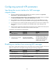
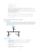
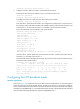
As shown in Figure 50, configure Device A as the reference source, with the stratum level 2. Configure
Device B to operate in client/server mode and use Device A as its NTP server..
Figure 50 Network diagram
Configuration procedure
1. Set the IP address for each interface as shown in Figure 50. (Details not shown.)
2. Configuration on Device A:
# Specify the local clock as the reference source, with the stratum level of 2.
<DeviceA> system-view
[DeviceA] ntp-service refclock-master 2
3. Configuration on Device B:
# View the NTP status of Device B before clock synchronization.
<DeviceB> display ntp-service status
Clock status: unsynchronized
Clock stratum: 16
Reference clock ID: none
Nominal frequency: 64.0000 Hz
Actual frequency: 64.0000 Hz
Clock precision: 2^7
Clock offset: 0.0000 ms
Root delay: 0.00 ms
Root dispersion: 0.00 ms
Peer dispersion: 0.00 ms
Reference time: 00:00:00.000 UTC Jan 1 1900 (00000000.00000000)
# Specify Device A as the NTP server of Device B so that Device B is synchronized to Device A.
<DeviceB> system-view
[DeviceB] ntp-service unicast-server 1.0.1.11
# View the NTP status of Device B after clock synchronization.
[DeviceB] display ntp-service status
Clock status: synchronized
Clock stratum: 3
Reference clock ID: 1.0.1.11
Nominal frequency: 64.0000 Hz
Actual frequency: 64.0000 Hz
Clock precision: 2^7