
R3721-F3210-F3171-HP High-End Firewalls System Management and Maintenance Configuration Guide-6PW101


12
1. The source device (Firewall) sends an ICMP echo request with the RR option being empty to the
destination device (Device B).
2. The intermediate device (Device A) adds the IP address of its outbound interface (1.1.2.1) to the
RR option of the ICMP echo request, and forwards the packet.
3. Upon receiving the request, the destination device copies the RR option in the request and adds the
IP address of its outbound interface (1.1.2.2) to the RR option. Then the destination device sends
an ICMP echo reply.
4. The intermediate device adds the IP address of its outbound interface (1.1.1.2) to the RR option in
the ICMP echo reply, and then forwards the reply.
5. Upon receiving the reply, the source device adds the IP address of its inbound interface (1.1.1.1)
to the RR option. Finally, you can get detailed information about routes from Firewall to Device B:
1.1.1.1 <-> {1.1.1.2; 1.1.2.1} <-> 1.1.2.2.
Ping and tracert example
Network requirements
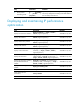
As shown in Figure 9, Firewall failed to Telnet Device B. Verify whether Firewall and Device B can reach
each other. If they cannot reach each other, locate the failed nodes in the network.
Figure 9 Network diagram
Test procedure
1. Use the ping command to verify whether Firewall and Device B can reach each other.
<Firewall> ping 1.1.2.2
PING 1.1.2.2: 56 data bytes, press CTRL_C to break
Request time out
Request time out
Request time out
Request time out
Request time out
--- 1.1.2.2 ping statistics ---
5 packet(s) transmitted
0 packet(s) received
100.00% packet loss
The output shows that Firewall and Device B cannot reach each other.
2. Use the tracert command to determine failed nodes.
# Enable sending of ICMP timeout packets on Device A.
<DeviceA> system-view
[DeviceA] ip ttl-expires enable
# Enable sending of ICMP destination unreachable packets on Device B.
<DeviceB> system-view
[DeviceB] ip unreachables enable