HP High-End Firewalls VPN Configuration Guide Part number: 5998-2652 Software version: F1000-A-EI&F1000-S-EI: R3721 F5000: F3210 F1000-E: F3171 Firewall module: F3171 Document version: 6PW101-20120719
Legal and notice information © Copyright 2012 Hewlett-Packard Development Company, L.P. No part of this documentation may be reproduced or transmitted in any form or by any means without prior written consent of Hewlett-Packard Development Company, L.P. The information contained herein is subject to change without notice.
Contents Configuring GRE ·························································································································································· 1 Overview············································································································································································ 1 GRE encapsulation format ··························································································································
Protocols and standards ······································································································································· 62 AFT configuration task list ············································································································································· 62 Configuring AFT ····························································································································································· 63
Configuring the CPE of a tunnel ························································································································ 105 Configuring the AFTR of a tunnel······················································································································· 106 Configuration example ······································································································································· 107 Configuring an IPv6 over IPv6 tunnel
IPsec for IPv6 routing protocols ·························································································································· 151 IPsec RRI································································································································································ 151 IPsec stateful failover ··········································································································································· 152 Protocols
Configuring a peer node ···································································································································· 225 Configuring L2TP ····················································································································································· 229 Overview······································································································································································· 229
Configuring PKI certificate verification ·············································································································· 305 Destroying a local RSA key pair ························································································································ 306 Deleting a certificate ··········································································································································· 307 Configuring an access control po
User access to SSL VPN ······································································································································ 372 SSL VPN configuration example ························································································································ 376 Configuring DVPN ·················································································································································· 394 Feature and hardware compa
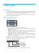
Configuring GRE Overview Generic Routing Encapsulation (GRE) is a protocol designed for encapsulating and carrying the packets of one network layer protocol (for example, IP) over another network layer protocol (for example, IP). The path that transfers the encapsulated packets is referred to as a GRE tunnel. A GER tunnel is a virtual point-to-point (P2P) connection. Packets are encapsulated at one end of the tunnel and de-encapsulated at the other end.
• GRE over IPv4—The transport protocol is IPv4, and the passenger protocol is any network layer protocol. • GRE over IPv6—The transport protocol is IPv6, and the passenger protocol is any network layer protocol. GRE encapsulation and de-encapsulation processes Figure 3 X protocol networks interconnected through a GRE tunnel The following sections use Figure 3 to describe how an X protocol packet traverses the IP network through a GRE tunnel. Encapsulation process 1.
• If the Key Present field of a GRE packet header is set to 1, the Key field will carry the key for the receiver to authenticate the source of the packet. This key must be the same at both ends of a tunnel. Otherwise, packets delivered over the tunnel will be discarded. • If the Checksum Present bit of a GRE packet header is set to 1, the Checksum field contains valid information.
VPN establishment by connecting discontinuous subnets Figure 6 Connect discontinuous subnets with a tunnel to form a VPN In the example as shown in Figure 6, Group 1 and Group 2 running Novell IPX are deployed in different cities. They can constitute a trans-WAN virtual private network (VPN) through the tunnel.
Configuration task list Task Creating a GRE over IPv4 tunnel interface Remarks Required. Create a tunnel interface and configure GRE over IPv4 tunnel related parameters. Optional. Configuring a route for packet forwarding through the tunnel Each end of the tunnel must have a route (static or dynamic) for packet forwarding through the tunnel to the other end, so that GRE encapsulated packets can be forwarded normally.
Table 1 Configuration items Item Description Tunnel Interface Specify the number of the tunnel interface. Specify the IP address and subnet mask of the tunnel interface. IP/Mask IMPORTANT: When configuring a static route on the tunnel interface, note that the destination IP address of the static route must not be in the subnet of the tunnel interface. Zone Tunnel Source IP/Interface Specify the security zone to which the tunnel interface belongs.
Figure 10 Network diagram NOTE: Before the configuration, make sure that Device A and Device B have IP connectivity to each other. Configuring Device A # Configure an IPv4 address for each interface and assign the interfaces to security zones. (Details not shown.) # Create a GRE tunnel interface. • Select VPN > GRE > GRE from the navigation tree and then click Add to perform the configurations shown in Figure 11. Figure 11 Creating a GRE tunnel interface • Enter 0 in the Tunnel Interface field.
Figure 12 Adding a static route from Device A through interface Tunnel0 to Group 2 • Enter 10.1.3.0 as the destination IP address. • Select mask 255.255.255.0. • Select Tunnel0 as the outbound interface. • Click Apply. Configuring Device B The configuration pages of Device B are similar to those of Device A. See the figures provided for configurations on Device A. # Configure an IPv4 address and assign the interfaces to security zones. (Details not shown.) # Create a GRE tunnel interface.
Figure 13 Status information and statistics of interface Tunnel0 # From Device B, ping the IP address of GigabitEthernet 0/2 on Device A. ping 10.1.1.1 PING 10.1.1.1: 56 data bytes, press CTRL_C to break Reply from 10.1.1.1: bytes=56 Sequence=1 ttl=255 time=2 ms Reply from 10.1.1.1: bytes=56 Sequence=2 ttl=255 time=2 ms Reply from 10.1.1.1: bytes=56 Sequence=3 ttl=255 time=2 ms Reply from 10.1.1.1: bytes=56 Sequence=4 ttl=255 time=2 ms Reply from 10.1.1.
• You can enable or disable the checksum function at both ends of the tunnel as needed. If the checksum function is enabled at the local end but not at the remote end, the local end calculates the checksum of a packet to be sent but does not check the checksum of a received packet. Contrarily, if the checksum function is enabled at the remote end but not at the local end, the local end checks the checksum of a received packet but does not calculate the checksum of a packet to be sent.
Step Command Remarks Optional. 9. Configure the key for the GRE tunnel interface. gre key key-number By default, no key is configured for a GRE tunnel interface. The two ends of a tunnel must have the same key or have no key at the same time. 10. Configure a route for packet forwarding through the tunnel. See Network Management Configuration Guide Each end of the tunnel must have a route (static or dynamic) through the tunnel to the other end. 11. Return to system view. quit N/A 12.
[RouterA-GigabitEthernet0/2] quit # Create a tunnel interface Tunnel0. [RouterA] interface tunnel 0 # Configure an IPv4 address for interface Tunnel0. [RouterA-Tunnel0] ip address 10.1.2.1 255.255.255.0 # Configure the tunnel encapsulation mode as GRE over IPv4. [RouterA-Tunnel0] tunnel-protocol gre # Configure the source address of interface Tunnel0 to be the IP address of GigabitEthernet 0/2. [RouterA-Tunnel0] source 1.1.1.
Tunnel0 current state: UP Line protocol current state: UP Description: Tunnel0 Interface The Maximum Transmit Unit is 1476 Internet Address is 10.1.2.1/24 Primary Encapsulation is TUNNEL, service-loopback-group ID not set. Tunnel source 1.1.1.1, destination 2.2.2.
Reply from 10.1.1.1: bytes=56 Sequence=3 ttl=255 time=2 ms Reply from 10.1.1.1: bytes=56 Sequence=4 ttl=255 time=2 ms Reply from 10.1.1.1: bytes=56 Sequence=5 ttl=255 time=2 ms --- 10.1.1.1 ping statistics --5 packet(s) transmitted 5 packet(s) received 0.00% packet loss round-trip min/avg/max = 2/2/2 ms Configuring a GRE over IPv6 tunnel NOTE: The GRE over IPv6 tunnel configuration is available only at the CLI.
Configuration procedure To configure a GRE over IPv6 tunnel: Step Command Remarks 1. Enter system view. system-view N/A 2. Enable the IPv6 packet forwarding function. ipv6 Disabled by default. 3. Create a tunnel interface and enter tunnel interface view. interface tunnel interface-number By default, no tunnel interface is created on the firewall. 4. Configure an IPv4 address for the tunnel interface.
GRE over IPv6 tunnel configuration example NOTE: In this configuration example, either Router A or Router B is the firewall. Network requirements Two IPv4 subnets Group 1 and Group 2 are connected to an IPv6 network. Create a GRE over IPv6 tunnel between Router A and Router B, so that the two IPv4 subnets can communicate with each other through the GRE tunnel over the IPv6 network.
# Configure a static route from Router A through interface Tunnel0 to Group 2. [RouterA] ip route-static 10.1.3.0 255.255.255.0 tunnel 0 2. Configure Router B: system-view # Enable IPv6. [RouterB] ipv6 # Configure an IPv4 address for interface GigabitEthernet 0/1. [RouterB] interface gigabitethernet 0/1 [RouterB-GigabitEthernet0/1] ip address 10.1.3.1 255.255.255.
Output queue : (FIFO queuing : Size/Length/Discards) Last clearing of counters: Last 300 seconds input: 0 bytes/sec, 0 packets/sec Last 300 seconds output: 10 packets input, 0/75/0 Never 0 bytes/sec, 0 packets/sec 840 bytes 0 input error 10 packets output, 840 bytes 0 output error [RouterB] display interface Tunnel 0 Tunnel0 current state: UP Line protocol current state: UP Description: Tunnel0 Interface The Maximum Transmit Unit is 1456 Internet Address is 10.1.2.
Displaying and maintaining GRE Task Display information about a specific or all tunnel interfaces. Display IPv6 information about a tunnel interface.
Configuring a point to multi-point GRE tunnel P2MP GRE tunnel overview Figure 17 P2MP GRE tunnel application scenario A traditional GRE tunnel is a point to point connection. To use traditional GRE tunnels on an enterprise network shown as Figure 17, you need to configure a P2P GRE tunnel between the headquarters and each branch.
Figure 18 Learning tunnel destination addresses dynamically Dest 10.1.1.0/24 Tun Dest 11.1.1.2 Headquarters Branch 11.1.1.2 GRE 10.1.1.2 Device A Device B 11.1.1.1/24 IPv4 network 11.1.1.2/24 GRE tunnel Tunnel0 10.3.1.1/24 Tunnel0 10.3.1.2/24 10.2.1.2/24 10.1.1.2/24 Host A Host B Different from a P2P GRE tunnel interface, a P2MP GRE tunnel interface does not require manual configuration of the tunnel destination addresses but learns them from GRE tunnel packets received from peers.
P2MP GRE tunnel backup GRE tunnel backup at a branch Figure 19 GRE tunnel backup at a branch As shown in Figure 19, for higher network reliability, a branch can use multiple gateway devices so that a GRE tunnel is established between the headquarters and each gateway of the branch for GRE tunnel backup. When creating a GRE tunnel on a gateway of the branch, you can configure the GRE key.
GRE tunnel backup at the headquarters Figure 20 GRE tunnel backup at the headquarters Headquarters Device A Host A Tunnel0 Branch Tunnel1 Back interface Tunnel0 Device C IPv4 network Tunnel1 Tunnel1 Host C Tunnel0 GRE P2MP tunnel Host B Device B (Backup gateway) GRE over IPv4 tunnel As shown in Figure 20, for higher network reliability, you can deploy multiple gateways at the headquarters and specify one or more backup interfaces for the main tunnel interface on the main gateway, such as Tunnel
• High reliability. It supports GRE tunnel backup at the headquarters and branches, improving the network reliability. The P2MP GRE tunnel technology has the following restrictions: • Both the transport protocol and passenger protocol must be IPv4. • The headquarters node cannot send packets to a branch before the branch sends packets to it. Only after receiving a packet from the branch, can the headquarters node installs a tunnel entry for the branch and send packets to the branch.
Configuring a P2MP GRE tunnel interface Select VPN > GRE > P2MP from the navigation tree to enter the P2MP GRE tunnel interface management page, as shown in Figure 21. Then, click Add to add a P2MP GRE tunnel interface, as shown in Figure 22. Figure 21 P2MP GRE tunnel interface management page Figure 22 Adding a P2MP GRE tunnel interface Table 2 Configuration items Item Description Tunnel Interface Specify the number of the tunnel interface.
Item Description Specify the source IP address for the tunnel interface. You can input an IP address or select an interface. In the latter case, the primary IP address of the interface will be used as the tunnel source address. Tunnel Source IP/Interface IMPORTANT: • You must configure a source address on a P2MP GRE tunnel interface. Two or more P2MP GRE tunnel interfaces cannot share the same source address.
Figure 23 Tunnel list Table 3 Field description Field Description Tunnel Interface Name of the tunnel interface Tunnel Dest Address IP address of the tunnel destination Branch Network Address/Mask IP address and mask of the branch network GRE Key GRE key of the tunnel, used to identify the priority of the tunnel entry. If the tunnel peer device is not configured with a GRE key, nothing will be displayed for this field.
Figure 24 Network diagram Configuring Device A 1. Configure an IPv4 address for each interface and assign the interfaces to security zones. (Details not shown.) 2. Create a P2MP GRE tunnel interface: a. Select VPN > GRE > P2MP from the navigation tree b. Click Add to perform the configurations shown in Figure 25. Figure 25 Add a P2MP GRE tunnel interface c. Enter 0 in the Tunnel Interface field. Enter IP address/mask 192.168.22.1/24. d. Select Management from the Zone list.
b. Click Add to perform the configurations shown in Figure 26. c. Enter 192.168.12.0 as the destination IP address. d. Select mask 255.255.255.0. e. Select Tunnel0 as the outbound interface. f. Click Apply. Figure 26 Adding a static route from Device A through interface Tunnel0 to the branch network Configuring Device B 1. Configure an IPv4 address for each interface and assign the interfaces to security zones. (Details not shown.) 2. Create a GRE over IPv4 tunnel interface: a.
Figure 27 Adding a GRE over IPv4 tunnel interface 3. Configure a static route from Device B through interface Tunnel0 to the headquarters node: a. Select Network > Routing Management > Static Routing from the navigation tree. b. Click Add to perform the configurations shown in Figure 28. c. Enter 192.168.11.0 as the destination IP address. d. Select mask 255.255.255.0. e. Select Tunnel0 as the outbound interface. f. Click Apply.
3. On Device A, click Refresh under the tunnel entry list. The P2MP GRE tunnel entry should have been installed, as shown in Figure 29. Figure 29 Verifying the configuration result Configuration example for P2MP GRE tunnel backup at the headquarters Network requirements As shown in Figure 30, the headquarters uses two gateways at the egress of the internal network, with Firewall B for backup.
Figure 30 Network diagram Headquarters Firewall A GE0/3 Host A GE0/1 Tunnel0 Branch GE0/2 Tunnel1 Tunnel0 Firewall C GE0/1 IPv4 network GE0/2 Tunnel1 Tunnel1 Host C GE0/2 GE0/1 Tunnel0 GRE P2MP tunnel GE0/3 Firewall B (Backup gateway) Host B GRE over IPv4 tunnel Device Interface IP address Device Interface IP address Firewall A GE0/1 11.1.1.1/24 Firewall B GE0/1 11.1.1.2/24 Firewall C GE0/2 10.1.1.1/24 GE0/2 10.1.1.2/24 GE0/3 192.168.11.1/24 GE0/3 192.168.11.
Figure 31 Add a GRE over IPv4 tunnel interface (Tunnel1) 3. Create a P2MP GRE tunnel interface, with the tunnel interface number being 0: a. Select VPN > GRE > P2MP from the navigation tree. b. Click Add to perform the configurations shown in Figure 32. c. Enter 0 in the Tunnel Interface field. d. Enter IP address/mask 172.168.1.1/24. e. Select Management from the Zone list. (Select a security zone according to your network configuration.) f. Enter 11.1.1.
Figure 32 Adding a P2MP GRE tunnel interface (Tunnel0) 4. Configure a static route from Firewall A through interface Tunnel0 to the branch network: a. Select Network > Routing Management > Static Routing from the navigation tree. b. Click Add to perform the configurations shown in Figure 33. c. Enter 192.168.12.0 as the destination IP address. d. Select mask 255.255.255.0. e. Select Tunnel0 as the outbound interface. f. Click Apply.
c. Enter 0 in the Tunnel Interface field. d. Enter IP address/mask 172.168.2.2/24. e. Select Management from the Zone list. (Select a security zone according to your network configuration.) f. Enter 11.1.1.2 as the tunnel source address, 24 as the branch network address mask, and 10 as the tunnel entry aging time. g. Click Apply. Figure 34 Adding a P2MP GRE tunnel interface (Tunnel0) 3. Create a GRE over IPv4 tunnel interface, with the tunnel interface number being 1: a.
Figure 35 Adding a GRE over IPv4 tunnel interface (Tunnel1) 4. Configure a static route from Firewall B through interface Tunnel0 to the branch network: a. Select Network > Routing Management > Static Routing from the navigation tree. b. Click Add to perform the configurations shown in Figure 36. c. Enter 192.168.12.0 as the destination IP address. d. Select mask 255.255.255.0. e. Select Tunnel0 as the outbound interface. f. Click Apply.
a. Select VPN > GRE > GRE from the navigation tree. b. Click Add to perform the configurations shown in Figure 37. c. Enter 0 in the Tunnel Interface field. d. Enter IP address/mask 172.168.1.3/24. e. Select Management from the Zone list. (Select a security zone according to your network configuration.) f. Enter the tunnel source IP address 11.1.1.3. g. Enter the tunnel destination IP address 11.1.1.1. h. Click Apply. Figure 37 Adding a GRE over IPv4 tunnel interface (Tunnel0) 3.
Figure 38 Adding a GRE over IPv4 tunnel interface (Tunnel1) 4. Configure a static route from Firewall C through interface Tunnel0 to the headquarters node, with the routing priority being 1. a. Select Network > Routing Management > Static Routing from the navigation tree. b. Click Add to perform the configurations shown in Figure 39. c. Enter 192.168.11.0 as the destination IP address. d. Select mask 255.255.255.0. e. Select Tunnel0 as the outbound interface. f. Enter priority 1. g. Click Apply.
This makes the priority of this route lower than that of the static route of interface Tunnel0, making sure that Firewall C prefers the tunnel between Firewall A and Firewall C for packet forwarding. a. On the static route management page, click Add to perform the configurations shown in Figure 40. b. Enter 192.168.11.0 as the destination IP address. c. Select mask 255.255.255.0. d. Select Tunnel1 as the outbound interface. e. Enter priority 10. f. Click Apply.
Figure 41 Verifying the configuration result on Firewall A 3. Perform the same operations on Firewall B and you can see that there is no P2MP GRE tunnel established on Firewall B. 4. Cut off the tunnel link between Firewall A and Firewall C: a. On Firewall C, select Device Management > Interface from the navigation tree and then click the icon of interface Tunnel0. b. Click the Disable button to shut down interface Tunnel0. 5.
Configuration example for P2MP GRE tunnel backup at a branch Network requirements As shown in Figure 43, a branch uses two gateways at the egress of the internal network, with Firewall C for backup. A P2MP GRE tunnel template is created on Firewall A, the gateway at the headquarters, allowing Firewall A to establish two GRE tunnels to the branch network, one for connecting Firewall B and the other for connecting Firewall C.
Figure 44 Adding a P2MP GRE tunnel interface 3. Configure a static route from Firewall A through interface Tunnel0 to the branch network: a. Select Network > Routing Management > Static Routing from the navigation tree. b. Click Add to perform the configurations shown in Figure 45. c. Enter 192.168.1.0 as the destination IP address. d. Select mask 255.255.255.0. e. Select Tunnel0 as the outbound interface. f. Click Apply.
c. Enter 0 in the Tunnel Interface field. d. Enter IP address/mask 192.168.22.2/24. e. Select Management from the Zone list. (Select a security zone according to your network configuration.) f. Enter the tunnel source IP address 11.1.1.2. g. Enter the tunnel destination IP address 11.1.1.1. h. Enter the GRE key 1. i. Click Apply. Figure 46 Adding a GRE over IPv4 tunnel interface 3.
Figure 47 Adding a static route from Firewall B through interface Tunnel0 to the headquarters node Configuring Firewall C 1. Configure an IPv4 address for each interface and assign the interfaces to security zones. (Details not shown.) 2. Create a GRE over IPv4 tunnel interface: a. Select VPN > GRE > GRE from the navigation tree. b. Click Add to perform the configurations shown in Figure 48. c. Enter 0 in the Tunnel Interface field. d. Enter IP address/mask 192.168.22.3/24. e.
Figure 48 Adding a GRE over IPv4 tunnel interface 3. Configure a static route from Firewall C through interface Tunnel0 to the headquarters node: a. Select Network > Routing Management > Static Routing from the navigation tree. b. Click Add to perform the configurations shown in Figure 49. c. Enter 172.17.17.0 as the destination IP address. d. Select mask 255.255.255.0. e. Select Tunnel0 as the outbound interface. f. Click Apply.
2. On Firewall A, select VPN > GRE > P2MP from the navigation tree and then click the Tunnel List tab. You can see information about the P2MP GRE tunnels established on Firewall A, as shown in Figure 50. Figure 50 Verifying the configuration result on Firewall A (1) 3. On Host B, specify Firewall B as the default gateway. Ping Host A from Host B. The ping operation succeeds. 4. Click the Refresh button under the tunnel list of Firewall A.
Figure 52 Verifying the configuration result on Firewall A (3) Configuring a P2MP GRE tunnel at the CLI Configuration guidelines • Two or more P2MP GRE tunnel interfaces cannot share the same source address. • If you specify a source interface for a P2MP GRE tunnel interface, the tunnel interface takes the primary IP address of the source interface as its source address. • You can enable or disable the checksum function at both ends of the tunnel as needed.
Step 2. 3. Command Remarks Create a tunnel interface and enter tunnel interface view. interface tunnel interface-number By default, no tunnel interface is created on the firewall. Configure an IPv4 address for the tunnel interface. ip address ip-address { mask | mask-length } By default, a tunnel interface has no IPv4 address. The default tunnel mode is GRE over IPv4. 4. Set the tunnel mode to P2MP GRE.
Displaying and maintaining P2MP GRE tunnels Task Command Remarks Display the tunnel entry information of a P2MP GRE tunnel interface. display gre p2mp tunnel-table interface tunnel number [ | { begin | exclude | include } regular-expression ] Available in any view Clear the tunnel entry information of a P2MP GRE tunnel interface.
Configuration procedure 1. Configure Router A: # Configure an IP address for interface GigabitEthernet 0/1. system-view [RouterA] interface gigabitethernet 0/1 [RouterA–GigabitEthernet0/1] ip address 11.1.1.1 255.255.255.0 [RouterA–GigabitEthernet0/1] quit # Configure an IP address for interface GigabitEthernet 0/2. [RouterA] interface gigabitethernet 0/2 [RouterA–GigabitEthernet0/2] ip address 192.168.11.1 255.255.255.
# Configure a static route to the headquarters network with the outgoing interface being Tunnel0. [RouterB] ip route-static 192.168.11.0 255.255.255.0 tunnel 0 Verifying the configuration # After the configurations, view the tunnel entry information on Router A. No tunnel entry exists. [RouterA] display gre p2mp tunnel-table interface tunnel 0 Dest Addr Mask Tunnel Dest Addr Gre Key # Ping Host A from Host B. The operation succeeds. # View tunnel entry information on Router A again.
Figure 54 Network diagram Headquarters Firewall A GE0/3 Host A GE0/1 Tunnel0 Branch GE0/2 Tunnel1 Tunnel0 Firewall C GE0/1 IPv4 network GE0/2 Tunnel1 Tunnel1 Host C GE0/2 GE0/1 Tunnel0 GRE P2MP tunnel GE0/3 Host B Firewall B (Backup gateway) GRE over IPv4 tunnel Device Interface IP Address Device Interface IP Address Firewall A GE0/1 11.1.1.1/24 Firewall B GE0/1 11.1.1.2/24 Firewall C GE0/2 10.1.1.1/24 GE0/2 10.1.1.2/24 GE0/3 192.168.11.1/24 GE0/3 192.168.11.
[FirewallA-Tunnel0] gre p2mp aging-time 20 # Configure the source IP address of interface Tunnel0. [FirewallA-Tunnel0] source 11.1.1.1 # Configure Tunnel 1 as the backup interface of Tunnel0. [FirewallA-Tunnel0] gre p2mp backup-interface tunnel 1 [FirewallA-Tunnel0] quit # Configure a static route to the branch network with the outgoing interface being Tunnel0. [FirewallA] ip route-static 192.168.12.0 255.255.255.0 tunnel 0 2.
# Configure a static route to the headquarters network with the outgoing interface being Tunnel0 and priority value being 1. [FirewallC] ip route-static 192.168.11.0 255.255.255.0 tunnel 0 preference 1 # Create tunnel interface Tunnel 1 and configure an IP address for it. [FirewallC] interface tunnel 1 [FirewallC-Tunnel1] ip address 172.168.2.3 255.255.255.0 # Configure the tunnel encapsulation mode of interface Tunnel1 as GRE over IPv4.
Dest Addr Mask Tunnel Dest Addr Gre Key # Ping Host A from Host C. View tunnel entries on Firewall B: [FirewallB] display gre p2mp tunnel-table interface tunnel 0 Dest Addr Mask Tunnel Dest Addr 192.168.12.0 255.255.255.0 11.1.1.3 Gre Key Then, Host A can ping Host C. The verification process indicates that: • After the link between Firewall A and Firewall C went down, the tunnel entry aging timer started to work. • After the timer expired, the tunnel entry on Firewall A was removed.
Configuration procedure Configure IP addresses and masks for interfaces as per Figure 43. (Details not shown.) 1. Configure Firewall A: # Create tunnel interface Tunnel0 and configure an IP address for it. system-view [FirewallA] interface tunnel 0 [FirewallA-Tunnel0] ip address 192.168.22.1 255.255.255.0 # Configure the tunnel encapsulation mode of interface Tunnel0 as P2MP GRE.
[FirewallC-Tunnel0] gre key 2 [FirewallC-Tunnel0] quit # Configure a static route to the headquarters network with the outgoing interface being Tunnel0. [FirewallC] ip route-static 172.17.17.0 255.255.255.0 tunnel 0 Verifying the configuration # On Host B, specify Firewall C as the default gateway. Ping Host A from Host B. The ping operation succeeds. View tunnel entries on Firewall A: [FirewallA] display gre p2mp tunnel-table interface tunnel 0 Dest Addr Mask Tunnel Dest Addr Gre Key 192.168.1.
Configuring AFT This chapter describes how to configure Address Family Translation (AFT). NOTE: AFT configuration is available only at CLI. Overview Application scenario AFT is a transition technology for communication between IPv4 and IPv6 networks. As Figure 56 shows, the AFT router performs address and protocol translation between IPv4 and IPv6 networks. With AFT, IPv6 and IPv4 hosts can communicate with one another without changing their configurations.
Figure 57 DNS64 prefix is added to an IPv4 address to translate it into an IPv6 address For an IPv4 packet sent from an IPv4 host to an IPv6 host, AFT translates its source IPv4 address to an IPv6 address by adding a DNS64 prefix. When an IPv6 host sends a packet to an IPv4 host, the destination IPv6 address is formed by adding the DNS64 prefix to the IPv4 address of the IPv4 host.
AFT operation AFT allows an IPv6 host to initiate communication with any IPv4 host, but allows an IPv4 host to initiate communication with only IPv6 hosts whose addresses are IVI addresses. The address translation process for communication initiated by an IPv6 host is different from that for communication initiated by an IPv4 host. Communication initiated by an IPv6 host Figure 59 AFT process when communication is initiated by an IPv6 host AFT operates in the following steps: 1.
NOTE: To view the address mappings, use the display session table command. For more information about this command, see Access Control Configuration Guide. Communication initiated by an IPv4 host Figure 60 AFT process when communication is initiated by an IPv4 host IPv6 addr: 3000:0:FF02:202:200:: Embedded IPv4 addr: 2.2.2.2 DNS64 prefix: 2000::/32 IVI prefix: 3000::/32 IPv4 addr: 1.1.1.1 Translated IPv6 addr: 2000:0:101:101:: AFT IPv6 host IPv4 host Dst: 2.2.2.2 Src: 1.1.1.
DNS64 function A DNS client in an IPv6 network cannot communicate with a DNS server in an IPv4 network because their address formats are different. The DNS64 function of AFT can solve this issue. When an IPv6 host sends an AAAA (IPv6) DNS query to an IPv4 DNS server, the destination IPv6 address is translated from the IPv4 address of the DNS server.
Task Remarks Enabling AFT Required. Configuring a DNS64 prefix Required. Configuring an IVI prefix Required. Configuring a 6to4 AFT policy Perform either one. Complete the following tasks to configure AFT for communication initiated by an IPv4 host: Task Remarks Enabling AFT Required. Configuring a DNS64 prefix Required. Configuring an IVI prefix Required. Configuring 4to6 AFT policies Required.
Configuring a DNS64 prefix Step Command Remarks 1. Enter system view. system-view N/A 2. Configure a DNS64 prefix. aft prefix-dns64 dns64-prefix prefix-length No DNS64 prefix is configured by default. NOTE: • The DNS64 prefix cannot be in the same network segment as the connected IPv6 network. • The DNS64 prefix cannot be the same as the IVI prefix. Configuring an IVI prefix Step Command Remarks 1. Enter system view. system-view N/A 2. Configure an IVI prefix.
Type 4—DNS64 prefix + interface address • If the prefix of the destination IPv6 address is the DNS64 prefix specified in the policy, AFT translates the source address into the IPv4 address of the specified interface. The port number is also translated. To configure the 6to4 AFT policy: Step 1. 2. Enter system view. Configure an AFT IPv4 address pool. Command Remarks system-view N/A aft address-group group-number start-ipv4-address end-ipv4-address Required for type 1 and type 3.
Step Command Remarks 1. Enter system view. system-view N/A 2. Configure the 4to6 AFT policy for source address translation. aft v4tov6 acl number acl-number prefix-dns64 dns64-prefix prefix-length Optional. 3. Configure the 4to6 AFT policy for destination address translation. aft v4tov6 acl number acl-number prefix-ivi ivi-prefix N/A NOTE: • The DNS64 and IVI prefixes must be those configured by the aft prefix-dns64 and aft prefix-ivi commands.
Figure 61 Network diagram Configuration procedure 1. Configure Firewall B (the AFT): # Enable IPv6. system-view [FirewallB] ipv6 # Configure IP addresses for the interfaces and enable AFT on the interfaces. [FirewallB] interface gigabitethernet 0/1 [FirewallB-GigabitEthernet0/1] ipv6 address 6:0:ff06:606:100::/64 [FirewallB-GigabitEthernet0/1] aft enable [FirewallB-GigabitEthernet0/1] quit [FirewallB] interface gigabitethernet 0/2 [FirewallB-GigabitEthernet0/2] ip address 4.4.4.
Verifying the configuration Execute the ping ipv6 2000:0:404:402:: command on Firewall A. The ping operation should be successful. # Execute the display session table verbose command on Firewall B to display the established sessions. [FirewallB] display session table verbose Initiator: Source IP/Port : 0006:0:ff06:0606:0200::/32768 Dest IP/Port : 2000:0:0404:0402::/43982 VPN-Instance/VLAN ID/VLL ID: Responder: Source IP/Port : 4.4.4.2/0 Dest IP/Port : 6.6.6.
[FirewallB-GigabitEthernet0/1] aft enable [FirewallB-GigabitEthernet0/1] quit [FirewallB] interface gigabitethernet 0/2 [FirewallB-GigabitEthernet0/2] ip address 4.4.4.1 24 [FirewallB-GigabitEthernet0/2] aft enable [FirewallB-GigabitEthernet0/2] quit # Configure the DNS64 prefix. [FirewallB] aft prefix-dns64 2000:: 32 # Configure the IVI prefix. [FirewallB] aft prefix-ivi 6:: # Create ACL 3000 to permit ICMP packets destined to the IPv4 network 6.6.6.0/24, which is embedded in the IVI address.
[FirewallC] interface gigabitethernet 0/1 [FirewallC-GigabitEthernet0/1] ip address 4.4.4.2 24 [FirewallC-GigabitEthernet0/1] quit # Configure a static route to the IPv4 network (6.6.6.0/24) embedded in the IVI address. [FirewallC] ip route-static 6.6.6.0 24 4.4.4.1 Verifying the configuration Execute the ping 6.6.6.2 command on Firewall C. The ping operation should be successful. # Execute the display session table verbose command on Firewall B to display the established sessions.
Figure 63 Network diagram IPv6 network Firewall A GE0/1 6::2/64 IPv4 network Firewall B GE0/1 6:0:/64 GE0/2 4.4.4.1/24 GE0/1 4.4.4.2/24 Firewall C GE0/3 3.3.3.1/24 3.3.3.5/24 DNS server Configuration procedure 1. Configure Firewall B (the AFT): # Enable IPv6. system-view [FirewallB] ipv6 # Configure IP addresses for the interfaces and enable AFT on the interfaces.
[FirewallB] aft 4to6 acl number 2000 prefix-dns64 2000:: 32 NOTE: It is optional to configure the 4to6 AFT policy for source address translation. If the policy is not configured, AFT uses the first configured DNS64 prefix to translate the resolved IPv4 address into an IPv6 address. Configure Firewall A: 2. # Enable IPv6. system-view [FirewallA] ipv6 # Configure an IPv6 address for interface GigabitEthernet 0/1.
bytes=56 Sequence=2 hop limit=254 time = 2 ms Reply from 2000:0:404:402:: bytes=56 Sequence=3 hop limit=254 time = 1 ms Reply from 2000:0:404:402:: bytes=56 Sequence=4 hop limit=254 time = 1 ms Reply from 2000:0:404:402:: bytes=56 Sequence=5 hop limit=254 time = 2 ms --- FirewallC.com ping statistics --5 packet(s) transmitted 5 packet(s) received 0.00% packet loss round-trip min/avg/max = 1/1/2 ms # Execute the display session table verbose command on Firewall B to display the established sessions.
Troubleshooting AFT Symptom 1 When an IPv6 host with a non-IVI address initiates communication with an IPv4 host, AFT fails to perform address translation. Solution • Enable debugging for AFT and locate the causes based on the debugging information. • Verify whether the translation of the source address is successful based on the debugging information. If not, the address pool might run out of IP addresses.
Configuring tunneling Overview Tunneling is an encapsulation technology. It uses one network protocol to encapsulate packets of another network protocol and transfer them over a virtual point-to-point connection. The virtual connection is called a tunnel. Packets are encapsulated and de-encapsulated at both ends of a tunnel. Tunneling refers to the whole process from data encapsulation to data transfer to data de-encapsulation.
The IPv6 over IPv4 tunnel processes packets in the following ways: 1. A host in the IPv6 network sends an IPv6 packet to Device A at the tunnel source. 2. After determining according to the routing table that the packet needs to be forwarded through the tunnel, Device A encapsulates the IPv6 packet with an IPv4 header and forwards it through the physical interface of the tunnel. 3. Upon receiving the packet, Device B de-encapsulates the packet. 4.
or between host and border router. For more information about related configurations, see "Configuring GRE." • 6to4 tunneling { Ordinary 6to4 tunneling An automatic 6to4 tunnel is a point-to-multipoint tunnel and is used to connect multiple isolated IPv6 networks over an IPv4 network to remote IPv6 networks. The embedded IPv4 address in an IPv6 address is used to automatically acquire the destination IPv4 address of the tunnel. The automatic 6to4 tunnel adopts 6to4 addresses.
When an ISATAP tunnel is used, the destination address of an IPv6 packet and the IPv6 address of a tunnel interface both adopt special ISATAP addresses. The ISATAP address format is prefix(64bit):0:5EFE:abcd:efgh. The 64-bit prefix is the prefix of a valid IPv6 unicast address, but abcd:efgh is a 32-bit source IPv4 address in hexadecimal, which might not be globally unique. Through the embedded IPv4 address, an ISATAP tunnel can be automatically created to transfer IPv6 packets.
• De-encapsulation The de-encapsulation follows these steps: a. After receiving the packet, Device A delivers it to the IP protocol stack, which then checks the protocol number in the IP header. b. If the protocol number is IPv4 (indicating an IPv4 packet is encapsulated within the packet), the IP packet is sent to the tunnel module for de-encapsulation. c. The de-encapsulated IP packet is sent back to the IP protocol stack for processing.
• IPv4 over IPv6 manual tunnel In this tunnel mode, you must manually configure the source and destination IPv6 addresses for the tunnel. An IPv4 over IPv6 manual tunnel is a point-to-point virtual link. • IPv4-over-IPv6 GRE tunnel The IPv4 over IPv6 GRE tunnel is also a point-to-point virtual link and the source and destination IPv6 address for the tunnel are also manually configured.
IPv6 address of each CPE so that IPv4 networks connected to different CPEs can use the same address space. • DS-lite tunnel—The IPv4 over IPv6 tunnel between the CPE and AFTR which carries IPv4 packets over an IPv6 network. Figure 70 Packet forwarding process in DS-lite When a gateway serves as the CPE, the changes of source and destination IP addresses and port numbers are illustrated in Figure 70. The entire process is summarized as follows: • The CPE and AFTR encapsulate and de-encapsulate packets.
IPv6 over IPv6 tunneling IPv6 over IPv6 tunneling (specified in RFC 2473) is developed for IPv6 data packet encapsulation so that encapsulated packets can be transmitted over an IPv6 network. The encapsulated packets are IPv6 tunnel packets. Figure 71 Principle of IPv6 over IPv6 tunneling Figure 71 shows the encapsulation and de-encapsulation processes. • Encapsulation a. After receiving the IPv6 packet, the interface of Device A connecting private network A submits it to the IPv6 module for processing.
• RFC 2893, Transition Mechanisms for IPv6 Hosts and Routers • RFC 3056, Connection of IPv6 Domains via IPv4 Clouds • RFC 4214, Intra-Site Automatic Tunnel Addressing Protocol (ISATAP) Tunneling configuration task list Task Remarks Configuring a tunnel interface Required. Configuring an IPv6 over IPv4 tunnel Configuring an IPv6 manual tunnel Optional. Configuring a 6to4 tunnel Use one as needed. Configuring an ISATAP tunnel Configuring an IPv4 over IPv4 tunnel Optional.
Step Command Shut down the tunnel interface. 7. Remarks Optional. shutdown By default, the interface is up. NOTE: • For more information about the ipv6 mtu command, see Network Management Command Reference. • The tunnel bandwidth command does not change the actual bandwidth of the tunnel interface, but sets a bandwidth value for dynamical routing protocols to calculate the cost of a tunnel path. You can determine the value according to the bandwidth of the output interface.
Step Command Remarks • Configure a global unicast IPv6 address or a site-local address: { 4. Configure an IPv6 address for the tunnel interface. { ipv6 address { ipv6-address prefix-length | ipv6-address/prefix-length } The link-local IPv6 address configuration is optional. By default, • No IPv6 global unicast address or site-local address is configured for the tunnel interface.
Figure 72 Network diagram Configuration procedure NOTE: Before configuring an IPv6 manual tunnel, make sure that Router A and Router B are reachable to each other. • Configure Router A: # Enable IPv6. system-view [RouterA] ipv6 # Configure an IPv4 address for GigabitEthernet 0/2. [RouterA] interface gigabitethernet 0/2 [RouterA-GigabitEthernet0/2] ip address 192.168.100.1 255.255.255.0 [RouterA-GigabitEthernet0/2] quit # Configure an IPv6 address for GigabitEthernet 0/1.
[RouterB] interface gigabitethernet 0/1 [RouterB-GigabitEthernet0/1] ipv6 address 3003::1 64 [RouterB-GigabitEthernet0/1] quit # Configure an IPv6 manual tunnel. [RouterB] interface tunnel 0 [RouterB-Tunnel0] ipv6 address 3001::2/64 [RouterB-Tunnel0] source gigabitethernet 0/2 [RouterB-Tunnel0] destination 192.168.100.1 [RouterB-Tunnel0] tunnel-protocol ipv6-ipv4 [RouterB-Tunnel0] quit # Configure a static route to IPv6 Group 1 through Tunnel 0 on Router B.
ND retransmit interval is 1000 milliseconds Hosts use stateless autoconfig for addresses IPv6 Packet statistics: InReceives: 55 ... # Ping the IPv6 address of GigabitEthernet 0/1 at the peer end from Router A.
Configuration procedure To configure a 6to4 tunnel: Step Command Remarks 1. Enter system view. system-view N/A 2. Enable IPv6. ipv6 By default, the IPv6 packet forwarding function is disabled. 3. Enter tunnel interface view. interface tunnel number N/A • Configure an IPv6 global unicast address or a site-local address: { 4. Configure an IPv6 address for the tunnel interface.
Figure 73 Network diagram Configuration consideration To enable communication between 6to4 networks, configure 6to4 addresses for 6to4 routers and hosts in the 6to4 networks. • The IPv4 address of GigabitEthernet 0/2 on Router A is 2.1.1.1/24, and the corresponding 6to4 prefix is 2002:0201:0101::/48 after it is translated to an IPv6 address. Assign interface Tunnel 0 to subnet 2002:0201:0101::/64 and GigabitEthernet 0/1 to subnet 2002:0201:0101:1::/64.
# Configure a static route whose destination address is 2002::/16 and next-hop is the tunnel interface. [RouterA] ipv6 route-static 2002:: 16 tunnel 0 • Configure Router B: # Enable IPv6. system-view [RouterB] ipv6 # Configure an IPv6 address for GigabitEthernet 0/2. [RouterB] interface gigabitethernet 0/2 [RouterB-GigabitEthernet0/2] ip address 5.1.1.1 24 [RouterB-GigabitEthernet0/2] quit # Configure an IPv6 address for GigabitEthernet 0/1.
Network requirements As shown in Figure 74, Router A is a 6to4 router, and 6to4 addresses are used on the connected IPv6 network. Router B serves as a 6to4 relay router and is connected to the IPv6 network (2001::/16). Configure a 6to4 tunnel between Router A and Router B to make Host A and Host B reachable to each other. Figure 74 Network diagram Configuration procedure NOTE: • Before configuring a 6to4 relay, make sure that Router A and Router B are reachable to each other.
# Configure the default route to the IPv6-only network. [RouterA] ipv6 route-static :: 0 2002:0601:0101::1 • Configure Router B: # Enable IPv6. system-view [RouterB] ipv6 # Configure an IPv4 address for GigabitEthernet 0/2. [RouterB] interface gigabitethernet 0/2 [RouterB-GigabitEthernet0/2] ip address 6.1.1.1 255.255.255.0 [RouterB-GigabitEthernet0/2] quit # Configure an IPv6 address for GigabitEthernet 0/1.
Configuring an ISATAP tunnel Configuration prerequisites Configure IP addresses for interfaces (such as the VLAN interface, GigabitEthernet interface, and loopback interface) on the firewall to ensure normal communication. One of the interfaces will be used as the source interface of the tunnel. Configuration guidelines Follow these guidelines when you configure an ISATAP tunnel: • No destination address needs to be configured for an ISATAP tunnel.
Step Command Remarks By default, the tunnel mode is GRE over IPv4. 5. Specify the ISATAP tunnel mode. tunnel-protocol ipv6-ipv4 isatap The same tunnel mode should be configured at both ends of the tunnel. Otherwise, packet delivery will fail. 6. Configure a source address or interface for the tunnel. source { ip-address | interface-type interface-number } By default, no source address or interface is configured for the tunnel. 7. Return to system view. quit N/A 8.
[Firewall-GigabitEthernet0/1] ip address 1.1.1.1 255.0.0.0 [Firewall-GigabitEthernet0/1] quit # Configure an ISATAP tunnel. [Firewall] interface tunnel 0 [Firewall-Tunnel0] ipv6 address 2001::5efe:0101:0101 64 [Firewall-Tunnel0] source gigabitethernet 0/1 [Firewall-Tunnel0] tunnel-protocol ipv6-ipv4 isatap # Disable the RA suppression so that hosts can acquire information such as the address prefix from the RA message released by the ISATAP router.
router link-layer address: 1.1.1.1 preferred global 2001::5efe:2.1.1.2, life 29d23h59m46s/6d23h59m46s (public) preferred link-local fe80::5efe:2.1.1.2, life infinite link MTU 1500 (true link MTU 65515) current hop limit 255 reachable time 42500ms (base 30000ms) retransmission interval 1000ms DAD transmits 0 default site prefix length 48 # By comparison, it is found that the host acquires the address prefix 2001::/64 and automatically generates the address 2001::5efe:2.1.1.2.
end. If you configure dynamic routing at both ends, enable the dynamic routing protocol on both tunnel interfaces. For the detailed configuration, see Network Management Configuration Guide. • The IPv4 address of the local tunnel interface cannot be on the same subnet as the destination address of the tunnel. • The destination address of a route with a tunnel interface as the egress interface must not be on the same subnet as the destination address of the tunnel.
Figure 76 Network diagram Configuration procedure NOTE: Before configuring an IPv4 over IPv4 tunnel, make sure that Router A and Router B are reachable to each other. • Configure Router A: # Configure an IPv4 address for GigabitEthernet 0/1. system-view [RouterA] interface gigabitethernet 0/1 [RouterA-GigabitEthernet0/1] ip address 10.1.1.1 255.255.255.0 [RouterA-GigabitEthernet0/1] quit # Configure an IPv4 address for GigabitEthernet 0/2 (the physical interface of the tunnel).
# Configure an IPv4 address for GigabitEthernet 0/2 (the physical interface of the tunnel). [RouterB] interface gigabitethernet 0/2 [RouterB-GigabitEthernet0/2] ip address 3.1.1.1 255.255.255.0 [RouterB-GigabitEthernet0/2] quit # Create interface Tunnel 2. [RouterB] interface tunnel 2 # Configure an IPv4 address for interface Tunnel 2. [RouterB-Tunnel2] ip address 10.1.2.2 255.255.255.0 # Configure the tunnel encapsulation mode.
Tunnel source 3.1.1.1, destination 2.1.1.
If you specify a source interface instead of a source address for the tunnel, the source address of the tunnel is the primary IP address of the source interface. • Configuration procedure To configure an IPv4 over IPv6 manual tunnel: Step Command Remarks 1. Enter system view. system-view N/A 2. Enable IPv6. ipv6 By default, the IPv6 packet forwarding function is disabled. 3. Enter tunnel interface view. interface tunnel number N/A 4. Configure an IPv4 address for the tunnel interface.
Figure 77 Network diagram Configuration procedure NOTE: Before configuring an IPv4 over IPv6 tunnel, make sure that Router A and Router B are reachable to each other. • Configure Router A: # Enable IPv6. system-view [RouterA] ipv6 # Configure an IPv4 address for GigabitEthernet 0/1. [RouterA] interface gigabitethernet 0/1 [RouterA-GigabitEthernet0/1] ip address 30.1.1.1 255.255.255.
# Configure an IPv4 address for GigabitEthernet 0/1. [RouterB] interface gigabitethernet 0/1 [RouterB-GigabitEthernet0/1] ip address 30.1.3.1 255.255.255.0 [RouterB-GigabitEthernet0/1] quit # Configure an IPv6 address for GigabitEthernet 0/2 (the physical interface of the tunnel). [RouterB] interface gigabitethernet 0/2 [RouterB-GigabitEthernet0/2] ipv6 address 2002::2:1 64 [RouterB-GigabitEthernet0/2] quit # Create interface Tunnel 2.
Description: Tunnel2 Interface The Maximum Transmit Unit is 64000 Internet Address is 30.1.2.
This section describes how to configure a DS-lite tunnel on the CPE. For how to configure an IPv4 over IPv6 manual tunnel on the CPE, see "Configuring an IPv4 over IPv6 manual tunnel." Configuration guidelines Follow these guidelines when you configure the CPE of a DS-lite tunnel: • Tunnel interfaces using the same encapsulation protocol must have different source and destination addresses.
• Configuring a destination address on the AFTR is unnecessary. When receiving a packet from the tunnel, the AFTR records the source IPv6 address of the packet and uses it as the IPv6 address of the tunnel destination (address of the CPE). • You must enable NAT on the AFTR's interface which is connected to the Internet. AFTR does not support static NAT mappings or VPN instance matching. If an ACL rule includes a VPN instance, the rule does not take effect.
Figure 78 Network diagram Configuration procedure NOTE: • Before configuring a DS-lite tunnel, make sure that Firewall A and Firewall B are reachable to each other. • In this example, Firewall A and Firewall C are in the same network segment. Otherwise, you must deploy a DHCPv6 relay agent between them. DHCPv6 relay agent is beyond the scope of this document. For more information about DHCPv6, see Network Management Configuration Guide. • Configure Firewall A (the CPE): # Enable IPv6.
# Enable IPv6. system-view [FirewallB] ipv6 # Configure an IPv6 address for interface GigabitEthernet 0/1 (the physical interface of the tunnel). [FirewallB] interface gigabitethernet 0/1 [FirewallB-GigabitEthernet0/1] ipv6 address 1::2 64 [FirewallB-GigabitEthernet0/1] quit # Configure an IPv4 address for interface GigabitEthernet 0/2. [FirewallB] interface gigabitethernet 0/2 [FirewallB- GigabitEthernet0/2] ip address 20.1.1.
Verifying the configuration # Display the status of the tunnel interfaces on Firewall A and Firewall B: [FirewallA] display interface tunnel 1 Tunnel1 current state: UP Line protocol current state: UP Description: Tunnel1 Interface The Maximum Transmit Unit is 1460 Internet Address is 30.1.2.1/24 Primary Encapsulation is TUNNEL, service-loopback-group ID not set.
Reply from 20.1.1.2: bytes=56 Sequence=4 ttl=255 time=1 ms Reply from 20.1.1.2: bytes=56 Sequence=5 ttl=255 time=1 ms --- 20.1.1.2 ping statistics --5 packet(s) transmitted 5 packet(s) received 0.00% packet loss round-trip min/avg/max = 1/1/1 ms Configuring an IPv6 over IPv6 tunnel Configuration prerequisites Configure IP addresses for interfaces (such as the VLAN interface, GigabitEthernet interface, and loopback interface) on the firewall to ensure normal communication.
Step Command Remarks • Configure an IPv6 global unicast address or site-local address: { 4. Configure an IPv6 address for the tunnel interface. { ipv6 address { ipv6-address prefix-length | ipv6-address/prefix-length } ipv6 address ipv6-address/prefix-length eui-64 • Configure an IPv6 link-local address: { { Use one of the commands. By default, no IPv6 address is configured for the tunnel interface. ipv6 address auto link-local ipv6 address ipv6-address link-local Optional.
Figure 79 Network diagram Configuration procedure NOTE: Before configuring an IPv6 over IPv6 tunnel, make sure that Router A and Router B are reachable to each other. • Configure Router A: # Enable IPv6. system-view [RouterA] ipv6 # Configure an IPv6 address for GigabitEthernet 0/1.
[RouterB] ipv6 # Configure an IPv6 address for GigabitEthernet 0/1. [RouterB] interface gigabitethernet 0/1 [RouterB-GigabitEthernet0/1] ipv6 address 2002:3::1 64 [RouterB-GigabitEthernet0/1] quit # Configure an IPv6 address for GigabitEthernet 0/2 (the physical interface of the tunnel). [RouterB] interface gigabitethernet 0/2 [RouterB-GigabitEthernet0/2] ipv6 address 2002::22:1 64 [RouterB-GigabitEthernet0/2] quit # Create interface Tunnel 2.
IPv6 is enabled, link-local address is FE80::2024:1 Global unicast address(es): 3001::1:2, subnet is 3001::/64 Joined group address(es): FF02::1:FF24:1 FF02::1:FF01:2 FF02::1:FF00:0 FF02::2 FF02::1 MTU is 1460 bytes ND reachable time is 30000 milliseconds ND retransmit interval is 1000 milliseconds Hosts use stateless autoconfig for addresses IPv6 Packet statistics: ... # Ping the IPv6 address of the peer interface GigabitEthernet 0/1 from Router A.
Troubleshooting tunneling configuration Symptom After the configuration of related parameters such as tunnel source address, tunnel destination address, and tunnel mode, the tunnel interface is still not up. Solution 1. The common cause is that the physical interface of the tunnel source is not up. Use the display interface tunnel or display ipv6 interface tunnel commands to view whether the physical interface of the tunnel source is up. If the physical interface is down, check the network connections.
Configuring IKE Feature and hardware compatibility Feature F1000-A-EI/S-EI F1000-E F5000 Firewall module FIPS No No No Yes IKE overview Built on a framework defined by the Internet Security Association and Key Management Protocol (ISAKMP), Internet Key Exchange (IKE) provides automatic key negotiation and SA establishment services for IPsec, simplifying the application, management, configuration and maintenance of IPsec dramatically.
1. Phase 1—The two peers establish an ISAKMP SA, a secure, authenticated channel for communication. In this phase, two modes are available: main mode and aggressive mode. 2. Phase 2—Using the ISAKMP SA established in phase 1, the two peers negotiate to establish IPsec SAs. Figure 80 IKE exchange process in main mode As shown in Figure 80, the main mode of IKE negotiation in phase 1 involves three pairs of messages: • SA exchange, used for negotiating the security policy.
Relationship between IKE and IPsec Figure 81 Relationship between IKE and IPsec SA negotiation IKE IKE Device A Device B TCP/UDP SA TCP/UDP IPsec IPsec Encrypted IP packets Figure 81 illustrates the relationship between IKE and IPsec: • IKE is an application layer protocol using UDP and functions as the signaling protocol of IPsec. • IKE negotiates SAs for IPsec and delivers negotiated parameters and generated keys to IPsec.
Configuring IKE in the web interface IKE configuration task list Task Remarks Configuring global IKE parameters Optional. Configure the IKE local name and NAT keepalive interval. This task is required when IKE peers need to specify an IKE proposal. The firewall has a default IKE proposal that has the lowest preference with the following default settings: • Pre-shared key as the authentication method. Configuring an IKE proposal • SHA as the authentication algorithm.
Table 5 Configuration items Item Description Enter a name for the local security gateway. IKE Local Name If the local device acts as the IKE negotiation initiator and uses the ID type of Fully Qualified Domain Name (FQDN) or the user FQDN of the security gateway for IKE negotiation, you need to configure this argument on the local device.
Figure 84 Adding an IKE proposal 3. Configure an IKE proposal as described in Table 6. 4. Click Apply. Table 6 Configuration items Item Description Enter the IKE proposal number. IKE Proposal Number The number also stands for the priority of the IKE proposal, with a smaller value meaning a higher priority. During IKE negotiation, the system matches IKE proposals in order of proposal number, starting from the smallest one. Select the authentication method to be used by the IKE proposal.
Item Description Select the DH group to be used in key negotiation phase 1. Options include: • Group1—Uses the 768-bit Diffie-Hellman group. This group is not available for the FIPS mode. DH Group • Group2—Uses the 1024-bit Diffie-Hellman group. It is the default group in FIPS mode. • Group5—Uses the 1536-bit Diffie-Hellman group. • Group14—Uses the 2048-bit Diffie-Hellman group. Enter the ISAKMP SA lifetime of the IKE proposal. Before an SA expires, IKE negotiates a new SA.
Figure 86 Adding an IKE DPD detector 3. Configure an IKE DPD as described in Table 7. 4. Click Apply. Table 7 Configuration items Item Description DPD Name Enter a name for the IKE DPD. DPD Query Triggering Interval Enter the interval after which DPD is triggered if no IPsec protected packets is received from the peer. DPD Packet Retransmission Interval Enter the interval after which DPD packet retransmission will occur if no DPD response is received. Configuring an IKE peer 1.
Figure 88 Adding an IKE peer 3. Configure an IKE peer as described in Table 5. 4. Click Apply. Table 8 Configuration items Item Description Peer Name Enter a name for the IKE peer. Select the IKE negotiation mode in phase 1, which can be Main or Aggressive. The aggressive mode is not available for the FIPS mode.
Item Description Select the local ID type for IKE negotiation phase 1. Options include: • IP Address—Uses an IP address as the ID in IKE negotiation. • FQDN—Uses the FQDN type as the ID in IKE negotiation. If this option is selected, enter a name string without any at sign (@) for the local security gateway, for example, foo.bar.com. Local ID Type • User FQDN—Uses a user FQDN type as the ID in IKE negotiation.
Item Description Enable the NAT traversal function for IPsec/IKE. The NAT traversal function must be enabled if a NAT security gateway exists in an IPsec/IKE VPN tunnel. In main negotiation mode, IKE does not support NAT traversal and this field is grayed out. Enable the NAT traversal function In FIPS mode, the IKE negotiation must use the main mode and you must configure NAT traversal at the CLI.
Field Description Status of the SA. Possible values include: • RD (ready)—Indicates that the SA has already been established and is ready for use. • ST (stayalive)—Indicates that the local end is the tunnel negotiation initiator. • RL (replaced)—Indicates that the tunnel has been replaced and will be cleared soon. • FD (fading)—Indicates that the soft lifetime expires but the tunnel is still in use. The tunnel will be deleted when the hard lifetime expires.
The IKE peer configuration page appears, as shown in Figure 91. b. Perform the following operations on the page: Enter peer as the peer name. Select Main as the negotiation mode. Enter 2.2.2.2 as the remote gateway IP address. Select Pre-Shared Key and enter abcde as the pre-shared key. c. Click Apply. Figure 91 Configuring the IKE peer 2. Create an IKE proposal numbered 10 on Device A: a. Select VPN > IKE > Proposal from the navigation tree and then click Add.
Figure 92 Creating an IKE proposal numbered 10 3. Configur ing the IKE peer on Device B: a. Select VPN > IKE > Peer from the navigation tree and then click Add. The IKE peer configuration page appears, as shown in Figure 91. b. Perform the following operations on the page: Enter peer as the peer name. Select Main as the negotiation mode. Enter 1.1.1.1 as the remote gateway IP address. Select Pre-Shared Key and enter abcde as the pre-shared key. c. Click Apply.
Task Remarks Configuring a DPD detector Optional. Disabling next payload field checking Optional. Configuring a name for the local security gateway If the IKE negotiation peer uses the security gateway name as its ID to initiate IKE negotiation (that is, the id-type name or id-type user-fqdn command is configured on the initiator), configure the ike local-name command in system view or the local-name command in IKE peer view on the local device.
Step Command Remarks Optional. 3. Specify an encryption algorithm for the IKE proposal. encryption-algorithm { 3des-cbc | aes-cbc [ key-length ] | des-cbc } The default encryption algorithm is 56-bit DES for the IKE proposal. In FIPS mode, the default encryption algorithm is AES-CBC-128. DES-CBC and 3DES-CBC algorithms are not available for the FIPS mode. 4. Specify an authentication method for the IKE proposal. authentication-method { pre-share | rsa-signature } Optional.
• Specify the ID type for the local end to use in IKE negotiation phase 1. With pre-shared key authentication, the ID type must be IP address for main mode IKE negotiation and can be IP address, FQDN, or user FQDN for aggressive mode IKE negotiation. • Specify the name or IP address of the local security gateway. You perform this task only when you want to specify a special address, a loopback interface address, for example, as the local security gateway address.
Step 7. 8. 9. Command Configure the names of the two ends. Configure the IP addresses of the two ends. Enable the NAT traversal function for IPsec/IKE. 10. Set the subnet types of the two ends. 11. Apply a DPD detector to the IKE peer. Remarks a. Specify a name for the local security gateway: local-name name b. Configure the name of the remote security gateway: remote-name name Optional.
with the TIMEOUT tag (if it does not have the tag), or be deleted along with the IPsec SAs it negotiated (when it has the tag already). To set the keepalive timers: Step Command Remarks 1. Enter system view. system-view N/A 2. Set the ISAKMP SA keepalive interval. ike sa keepalive-timer interval seconds No keepalive packet is sent by default. 3. Set the ISAKMP SA keepalive timeout. ike sa keepalive-timer timeout seconds No keepalive packet is sent by default.
Step Command Remarks 1. Enter system view. system-view N/A 2. Create a DPD detector and enter its view. ike dpd dpd-name N/A 3. Set the DPD interval. interval-time interval-time 4. Set the DPD packet retransmission interval. Optional. The default DPD interval is 10 seconds. Optional. time-out time-out The default DPD packet retransmission interval is 5 seconds.
IKE configuration examples at the CLI Main mode IKE with pre-shared key authentication configuration example Network requirements As shown in Figure 93, configure an IPsec tunnel that uses IKE negotiation between Firewall A and Firewall B to secure the communication between subnet 10.1.1.0/24 and subnet 10.1.2.0/24. For Firewall A, configure an IKE proposal that uses the sequence number 10 and authentication algorithm MD5. Leave Firewall B with only the default IKE proposal.
# Set the pre-shared key. [FirewallA-ike-peer-peer] pre-shared-key abcde # Specify the IP address of the peer security gateway. [FirewallA-ike-peer-peer] remote-address 2.2.2.2 [FirewallA-ike-peer-peer] quit # Create an IKE proposal numbered 10. [FirewallA] ike proposal 10 # Set the authentication algorithm to MD5. [FirewallA-ike-proposal-10] authentication-algorithm md5 # Set the authentication method to pre-shared key.
[FirewallB] ipsec proposal tran1 # Set the packet encapsulation mode to tunnel. [FirewallB-ipsec-proposal-tran1] encapsulation-mode tunnel # Use security protocol ESP. [FirewallB-ipsec-proposal-tran1] transform esp # Specify encryption and authentication methods. [FirewallB-ipsec-proposal-tran1] esp encryption-algorithm des [FirewallB-ipsec-proposal-tran1] esp authentication-algorithm sha1 [FirewallB-ipsec-proposal-tran1] quit # Create IKE peer peer. [FirewallB] ike peer peer # Set the pre-shared key.
10 PRE_SHARED MD5 DES_CBC MODP_768 5000 default PRE_SHARED SHA DES_CBC MODP_768 86400 [FirewallA] display ike proposal priority authentication authentication encryption Diffie-Hellman duration method algorithm algorithm group (seconds) --------------------------------------------------------------------------default PRE_SHARED SHA DES_CBC MODP_768 86400 The output shows that Firewall A and Firewall B have only one pair of matching IKE proposals.
sa duration (kilobytes/sec): 1843200/3600 sa remaining duration (kilobytes/sec): 1843199/3590 max received sequence-number: 4 anti-replay check enable: Y anti-replay window size: 32 udp encapsulation used for nat traversal: N [outbound ESP SAs] spi: 89389742 (0x553faae) proposal: ESP-ENCRYPT-DES ESP-AUTH-SHA1 sa duration (kilobytes/sec): 1843200/3600 sa remaining duration (kilobytes/sec): 1843199/3590 max received sequence-number: 5 udp encapsulation used for nat traversal: N Aggressive mode IKE with NAT
[Firewall] acl number 3101 [Firewall-acl-adv-3101] rule 0 permit ip source 172.16.0.0 0.0.0.255 destination 192.168.0.0 0.0.0.255 [Firewall-acl-adv-3101] quit # Configure an IKE proposal. [Firewall] ike proposal 1 [Firewall-ike-proposal-1] authentication-algorithm sha [Firewall-ike-proposal-1] authentication-method pre-share [Firewall-ike-proposal-1] encryption-algorithm 3des-cbc [Firewall-ike-proposal-1] dh group2 # Configure an IKE peer.
Configuring the router # Specify a name for the local security gateway. system-view [Router] ike local-name routerb # Configure an ACL. [Router] acl number 3101 [Router-acl-adv-3101] rule 0 permit ip source 192.168.0.0 0.0.0.255 destination 172.16.0.0 0.0.0.255 [Router-acl-adv-3101] quit # Configure an IKE proposal.
[Router] interface dialer 0 [Router-Dialer0] link-protocol ppp [Router-Dialer0] ppp pap local-user test password simple 123456 [Router-Dialer0] ip address ppp-negotiate [Router-Dialer0] dialer user 1 [Router-Dialer0] dialer-group 1 [Router-Dialer0] dialer bundle 1 [Router-Dialer0] ipsec policy policy [Router-Dialer0] mtu 1492 [Router-Dialer0] quit # Configure a static route to the headquarters LAN. [Router] ip route-static 172.16.0.0 255.255.255.0 dialer 0 # Configure interface GigabitEthernet 0/1.
Solution Check that the ACLs in the IPsec policies configured on the interfaces at both ends are compatible. Configure the ACLs to mirror each other. For more information about ACL mirroring, see " Configuring IPsec." Proposal mismatch Symptom The proposals mismatch. Analysis The following is the debugging information: got NOTIFY of type NO_PROPOSAL_CHOSEN Or drop message from A.B.C.D due to notification type NO_PROPOSAL_CHOSEN The two parties in the negotiation have no matched proposals.
Analysis When multiple devices create different IPsec tunnels early or late, a device may have multiple peers. If the device is not configured with ACL rule, the peers send packets to it to set up different IPsec tunnels in different protection granularity respectively. As the priorities of IPsec tunnels are determined by the order they are established, a device cannot interoperate with other peers in fine granularity when its outbound packets are first matched with an IPsec tunnel in coarse granularity.
Configuring IPsec The term "router" in this document refers to both routers and Layer 3 firewalls. Feature and hardware compatibility Feature F1000-A-EI/S-EI F1000-E F5000 Firewall module FIPS No No No Yes IPsec overview IP Security (IPsec) is a security framework defined by the Internet Engineering Task Force (IETF) for securing IP communications. It is a Layer 3 virtual private network (VPN) technology that transmits data in a secure tunnel established between two endpoints.
• AH (protocol 51), which provides data origin authentication, data integrity, and anti-replay services. For these purposes, an AH header is added to each IP packet. AH is suitable for transmitting non-critical data because it cannot prevent eavesdropping, although it can prevent data tampering. AH supports authentication algorithms such as Message Digest (MD5) and Secure Hash Algorithm (SHA-1).
• Transport mode—IPsec protects only the IP payload. It uses only the IP payload to calculate the AH or ESP header, and inserts the calculated header between the original IP header and payload. If you use ESP, an ESP trailer is also encapsulated. The transport mode is typically used for protecting host-to-host or host-to-gateway communications. Figure 95 shows how the security protocols encapsulate an IP packet in different encapsulation modes.
If the number of IPsec tunnels in your network is small, use the manual mode. If the number of IPsec tunnels is large, use the ISAKMP mode. IPsec tunnel An IPsec tunnel is a bidirectional channel created between two peers. An IPsec tunnel comprises one or more pairs of SAs. IPsec tunnel interface IPsec tunnel interface overview An IPsec tunnel interface is a Layer 3 logical interface. It supports dynamic routing.
3. The IPsec tunnel interface encapsulates the packet, and then sends the packet to the forwarding module. 4. The forwarding module looks up the routing table again and forwards the IPsec-encrypted packet out of the physical outbound interface that is associated with the tunnel interface. Figure 97 shows how an IPsec packet is de-encapsulated on an IPsec tunnel interface. Figure 97 De-encapsulation process of an IPsec packet 5.
branch. The result is the same as configuring a static route with the destination address 192.168.2.0/24 and the next hop 2.2.2.2. Figure 98 An IPsec VPN You can advertise the static routes created by IPsec RRI in the internal network. IPsec RRI can quickly create new routes for forwarding IPsec VPN traffic when an active link fails in a load balanced or stateful failover environment, or when IPsec VPN traffic cannot reach the peer gateway through the default local gateway.
As shown in Figure 99, Device A and Device B form a stateful failover system through a backup link. After the election process supported by the VRRP mechanism, Device A becomes the master. When Device A works normally, it establishes an IPsec tunnel to Device C, and synchronizes its IPsec service data to Device B. The synchronized IPsec service data includes the IKE SA, IPsec SAs, the anti-replay sequence number and window, the SA lifetime in units of bytes, and the DPD packet sequence number.
Recommended configuration procedure Step Remarks Required. Configure ACLs to identify the data flows to be protected by IPsec. 1. Configuring ACLs IMPORTANT: This document introduces only how to reference ACLs in IPsec. To create ACLs, select Firewall > ACL from the navigation tree. For more information about the procedure, see Access Control Configuration Guide. Required. 2.
The matching process stops once a match is found or ends with no match hit. The packet is handled as follows: • Each ACL rule matches both the outbound traffic and the returned inbound traffic. Suppose there is a rule as shown in Figure 100. This rule matches both traffic from 1.1.1.0 to 2.2.2.0 and returned traffic from 2.2.2.0 to 1.1.1.0.
Figure 101 ACL 3000 configuration on Device A Figure 102 ACL 3001 configuration on Device A Figure 103 IPsec policy configuration on Device A The configurations on Device B are shown in Figure 104, and Figure 105.
Figure 105 IPsec policy configuration on Device B Mirror image ACLs To make sure that SAs can be set up and the traffic protected by IPsec locally can be processed correctly at the remote peer, on the remote peer, create a mirror image ACL rule for each ACL rule created at the local peer. As shown in Figure 106, ACL rules on Device B are mirror images of the rules on Device A.
Figure 107 Non-mirror image ACLs Protection modes Data flows can be protected in the following modes: • Standard mode—in which one tunnel is used to protect one data flow. The data flow permitted by each ACL rule is protected by one tunnel that is established separately for it. • Aggregation mode—in which one tunnel is used to protect all data flows permitted by all the rules of an ACL. This mode applies to only scenarios that use IKE for negotiation.
Figure 109 IPsec proposal configuration wizard page 3. Click Suite mode to configure an IPsec proposal as described in Table 10, or click Custom mode to configure an IPsec proposal as described in Table 11. 4. Click Apply. Figure 110 IPsec proposal configuration in suite mode Table 10 Configuration items in suite mode Item Description Proposal Name Enter a name for the IPsec proposal. Select an encryption suite for the proposal.
Figure 111 IPsec proposal configuration in custom mode Table 11 Configuration items in custom mode Item Description Proposal Name Enter a name for the IPsec proposal. Encapsulation Mode Select an IP packet encapsulation mode for the IPsec proposal. Options include: • Tunnel—Uses the tunnel mode. • Transport—Uses the transport mode. Select a security protocol setting for the proposal. Options include: Security Protocol AH Authentication Algorithm • AH—Uses the AH protocol.
Item Description Select an encryption algorithm for ESP when the security protocol is ESP or AH-ESP. Options include: • DES—Uses the DES algorithm and 56-bit keys for encryption. In FIPS mode, DES is not supported and, if selected, does not take effect. • 3DES—Uses the 3DES algorithm and 168-bit keys for encryption. In FIPS mode, 3DES is not supported and, if selected, does not take effect. ESP Encryption Algorithm • • • • AES128—Uses the AES algorithm and 128-bit keys for encryption.
Figure 113 IPsec policy template configuration page Table 12 Configuration items Item Description Template Name Enter a name for the IPsec policy template. Enter a sequence number for the IPsec policy template. Sequence Number IKE Peer In an IPsec policy template group, an IPsec policy template with a smaller sequence number has a higher priority. Select an IKE peer for the IPsec policy template. You configure IKE peers by selecting VPN > IKE > Peer from the navigation tree.
Item Description Enable and configure the Perfect Forward Secrecy (PFS) feature or disable the feature. Options include: • dh-group1—Uses the 768-bit Diffie-Hellman group. In FIPS mode, dh-group1 is not supported, and if selected, does not take effect. • dh-group2—Uses the 1024-bit Diffie-Hellman group. • dh-group5—Uses the 1536-bit Diffie-Hellman group. • dh-group14—Uses the 2048-bit Diffie-Hellman group.
Configuring an IPsec policy 1. Select VPN > IPSec > Policy from the navigation tree to enter the IPsec policy management page. Figure 114 IPsec policy list 2. Click Add to enter the IPsec policy configuration page. 3. Configure an IPsec policy as described in Table 13. 4. Click Apply.
Table 13 Configuration items Item Description Policy Name Enter a name for the IPsec policy. Enter a sequence number for the IPsec policy. Sequence Number In an IPsec policy group, an IPsec policy with a smaller sequence number has a higher priority. Select an IPsec policy template. Template IMPORTANT: If you select an IPsec policy template, all subsequent configuration items but the aggregation setting are unavailable. IKE Peer Select an IKE peer for the IPsec policy.
Item Description Enable or disable IPsec RRI. When enabling IPsec RRI, you can specify a next hop and change the preference of the static routes. After an outbound IPsec SA is created, IPsec RRI automatically creates a static route to the peer private network. You do not have to manually configure the static route. Reverse Route Injection IMPORTANT: • If you enable IPsec RRI and do not configure the static route, the SA negotiation must be initiated by the remote gateways.
Figure 117 IPsec policy application page Table 14 Configuration items Item Description Interface Displays the interface you selected. Policy Select an IPsec policy group for the interface. Displaying IPsec SAs Select VPN > IPSec > IPSec SA from the navigation tree to display brief information about established IPsec SAs, as shown in Figure 118. Table 15 describes the fields of IPsec SA information.
Figure 119 Packet statistics Configuring ACL-based IPsec at the CLI Configuration task list Task Remarks Configuring ACLs Required. Configuring an IPsec proposal Basic IPsec configuration. Applying an IPsec policy group to an interface Enabling the encryption engine Required. Enabling ACL checking of de-encapsulated IPsec packets Optional. Configuring the IPsec anti-replay function Optional. Configuring packet information pre-extraction Optional. Enabling invalid SPI recovery Optional.
identifies a data flow that is not protected by IPsec. With IPsec, a packet is matched against the referenced ACL rules and processed according to the first rule that it matches: • Each ACL rule matches both the outbound traffic and the returned inbound traffic. Suppose there is a rule rule 0 permit ip source 1.1.1.0 0.0.0.255 destination 2.2.2.0 0.0.0.255. This rule matches both traffic from 1.1.1.0 to 2.2.2.0 and traffic from 2.2.2.0 to 1.1.1.0.
security acl 3001 ike-peer bb proposal 1 Configuration on Router B: acl number 3001 rule 0 permit ip source 3.3.3.0 0.0.0.255 destination 1.1.2.0 0.0.0.255 rule 1 deny ip # ipsec policy test 1 isakmp security acl 3001 ike-peer aa proposal 1 Mirror image ACLs See "Mirror image ACLs." Protection modes See "Protection modes.
Step Command Remarks • Specify the encryption Optional. algorithm for ESP: esp encryption-algorithm { 3des | aes [ key-length ] | des } 4. Specify the security algorithms. • Specify the authentication algorithm for ESP: esp authentication-algorithm { md5 | sha1 } • Specify the authentication algorithm for AH: ah authentication-algorithm { md5 | sha1 } By default, the encryption algorithm for ESP is DES, the authentication algorithm for ESP is MD5, and the authentication algorithm for AH is MD5.
The keys for the local and remote inbound and outbound SAs must be in the same format. For example, if the local inbound SA uses a key in characters, the local outbound SA and remote inbound and outbound SAs must use keys in characters. • Follow these guidelines when you configure an IPsec policy for an IPv6 routing protocol: • You do not need to configure ACLs or IPsec tunnel addresses.
Step 6. 7. Command Remarks Configure the remote address of the tunnel. tunnel remote ip-address Not configured by default. Configure the SPIs for the SAs. sa spi { inbound | outbound } { ah | esp } spi-number N/A • Configure an authentication key in hexadecimal for AH: sa authentication-hex { inbound | outbound } ah hex-key • Configure an authentication key in characters for AH: sa string-key { inbound | outbound } ah string-key 8. Configure keys for the SAs.
will be determined by the initiator. This approach applies to scenarios where the remote end's information, such as the IP address, is unknown. The parameters configurable for an IPsec policy template are the same as those you configure when directly configuring an IPsec policy that uses IKE. The difference is that more parameters are optional: • Required configuration: The IPsec proposals and IKE peer. • Optional configuration: The ACL, PFS feature, and SA lifetime.
Step Command Remark 4. Assign an ACL to the IPsec policy. security acl acl-number [ aggregation ] By default, an IPsec policy references no ACL. 5. Assign IPsec proposals to the IPsec policy. proposal proposal-name&<1-6> By default, an IPsec policy references no IPsec proposal. 6. Specify an IKE peer for the IPsec policy. ike-peer peer-name An IPsec policy cannot reference any IKE peer that is already referenced by an IPsec profile, and vice versa. Optional. 7.
Step 5. Specify the IKE peer for the IPsec policy to reference. Command Remark ike-peer peer-name An IPsec policy cannot reference any IKE peer that is already referenced by an IPsec profile, and vice versa. Optional. 6. Enable and configure the perfect forward secrecy feature for the IPsec policy. pfs { dh-group1 | dh-group2 | dh-group5 | dh-group14 } By default, the PFS feature is not used for negotiation. In FIPS mode, the firewall does not support the dh-group1 keyword.
To apply an IPsec policy group to an interface: Step Command Remarks 1. Enter system view. system-view N/A 2. Enter interface view. interface interface-type interface-number N/A 3. Apply an IPsec policy group to the interface. ipsec policy policy-name An interface can reference only one IPsec policy group. An IPsec policy that uses IKE can be applied to more than one interface, but a manual IPsec policy can be applied to only one interface.
resulting in DoS. IPsec anti-replay checking, when enabled, is performed before the de-encapsulation process, reducing resource waste. In some cases, however, the sequence numbers of some normal service data packets may be out of the current sequence number range, and the IPsec anti-replay function may drop them as well, affecting the normal communications. If this happens, disable IPsec anti-replay checking or adjust the size of the anti-replay window as required.
Enabling invalid SPI recovery When the security gateway at one end of an IPsec tunnel loses its SAs due to rebooting or any other reason, its peer security gateway may not know the problem and send IPsec packets to it. These packets will be discarded by the receiver because the receiver cannot find appropriate SAs for them, resulting in a traffic blackhole. This situation changes only after the concerned SAs on the sender get aged out and new SAs are established between the two peers.
• Change their route preference for equal-cost multipath (ECMP) routing or route backup. If multiple routes to the same destination have the same preference, traffic is balanced among them. If multiple routes to the same destination have different preference values, the route with the highest preference forwards traffic and all other routes are backup routes. • Change their tag value so the gateway can control the use of the static routes based on routing policies. To configure IPsec RRI: Step 1.
3. Configure an IPsec tunnel interface and apply the IPsec profile to the interface. NOTE: Because packets routed to the IPsec tunnel interface are all protected, the data protection scope, which is required for IPsec policy configuration, is not needed in the IPsec profile. Complete the following tasks to configure tunnel interface-based IPsec: Task Remarks Required. Configuring an IPsec proposal An IPsec proposal for the IPsec tunnel interface to reference supports tunnel mode only.
NOTE: • During an IKE negotiation based on an IPsec profile, the source and destination addresses of the IPsec tunnel interface are used as the local and remote addresses; the local-address and remote-address commands configured for IKE negotiation do not take effect. • If you do not configure the destination address of the IPsec tunnel interface, the local peer can only be an IKE negotiation responder; it cannot initiate an IKE negotiation. To configure an IPsec profile: Step Command Remarks 1.
Configuring an IPsec tunnel interface An IPsec tunnel interface uses IPsec as the encapsulation protocol. To configure an IPsec tunnel interface, complete the following tasks: 1. Create a tunnel interface and set the tunnel mode to IPsec over IPv4. 2. Specify the source address or source interface of the IPsec tunnel interface, which will be used as the local address in IKE negotiation. 3. Configure the destination addresses of the tunnel interface for the local peer to initiate an IKE negotiation.
NOTE: • An IPsec profile can be applied to an IPsec tunnel interface only. • An IPsec tunnel interface can reference only one IPsec profile. • Apply an IPsec profile to only one IPsec tunnel interface. Although an IPsec profile can be applied to multiple IPsec tunnel interfaces, it takes effect only on the IPsec tunnel interface that goes up first.
Step Command Remarks 1. Enter system view. system-view N/A 2. Enter tunnel interface view. interface tunnel number N/A 3. Apply a QoS policy to the IPsec tunnel interface. qos apply policy policy-name { inbound | outbound } For more information about this command, see Network Management Command Reference. Configuring IPsec for IPv6 routing protocols NOTE: The IPsec for IPv6 routing protocols configuration is available only at the CLI.
Configuring stateful failover • Configure the devices to operate in the active/standby mode. • Specify the failover interface for transferring state negotiation messages and backing up IPsec service data. For more information about stateful failover, see High Availability Configuration Guide. Configuring VRRP • On each device, configure a VRRP group for the uplink interface and a VRRP group for the downlink interface, and assign virtual IP addresses to the groups.
Task Command Remarks Display IPsec policy template information. display ipsec policy-template [ brief | name template-name [ seq-number ] ] [ | { begin | exclude | include } regular-expression ] Available in any view Display the configuration of IPsec profiles. display ipsec profile [ name profile-name ] [ | { begin | exclude | include } regular-expression ] Available in any view Display IPsec proposal information.
# Define ACL 3101 to permit packets from subnet 10.1.1.0/24 to subnet 10.1.2.0/24. Select Firewall > ACL from the navigation tree, click Add, and then perform the configurations shown in Figure 121. Figure 121 Create ACL 3101 • Enter 3101 as the ACL number. • Select the match order of Config. • Click Apply. From the ACL list, select ACL 3101 and click the icon. Then, click Add to enter the ACL rule configuration page and perform the configurations shown in Figure 122.
# Configure an IPsec proposal named tran1, and configure the proposal as follows. Select VPN > IPSec > Proposal from the navigation tree, click Add, select Custom mode from the IPSec Proposal Configuration Wizard page, and perform the configurations shown in Figure 123. Figure 123 Configure IPsec proposal tran1 • Enter tran1 as the name of the IPsec proposal. • Select Tunnel as the packet encapsulation mode. • Select ESP as the security protocol. • Select SHA1 as the ESP authentication algorithm.
Figure 124 Configure an IKE peer • Enter peer as the peer name. • Select Main as the negotiation mode. • Enter 2.2.3.1 as the IP address of the remote gateway. • Select Pre-Shared Key and enter abcde as the pre-shared key. • Click Apply. # Configure an IPsec policy. Select VPN > IPSec > Policy from the navigation tree and then click Add to enter the IPsec policy configuration page appears. Perform the configurations shown in Figure 125.
Figure 125 Configure an IPsec policy • Enter map1 as the policy name. • Enter 10 as the sequence number. • Select the IKE peer of peer. • Select the IPsec proposal of tran1 and click <<. • Enter 3101 as the ACL. • Select Enable for RRI. • Enter 2.2.2.2 as the next hop. • Click Apply. # Apply the IPsec policy to interface GigabitEthernet 0/1.
Figure 126 Apply IPsec policy to interface GigabitEthernet 0/1 • Select the policy of map1. • Click Apply. Configuring Device B NOTE: The configuration steps on Device B are similar to those on Device A. The configuration pages are not shown. # Assign IP addresses for the interfaces and then add them to the target zones. (Details not shown.) # Define an ACL to permit traffic from subnet 10.1.2.0/24 to subnet 10.1.1.0/24. • Select Firewall > ACL from the navigation tree, and then click Add.
• Select SHA1 as the ESP authentication algorithm. • Select DES as the ESP encryption algorithm. • Click Apply. # Configure IKE peer peer. • Select VPN > IKE > Peer from the navigation tree and then click Add. • Enter peer as the peer name. • Select Main as the negotiation mode. • Enter 2.2.2.1 as the IP address of the remote gateway. • Select Pre-Shared Key and enter abcde as the pre-shared key. • Click Apply. # Configure IPsec policy map1.
Figure 127 Network diagram Configuring Firewall A # Define an ACL to identify data flows from subnet 10.1.1.0/24 to subnet 10.1.2.0/24. system-view [FirewallA] acl number 3101 [FirewallA-acl-adv-3101] rule permit ip source 10.1.1.0 0.0.0.255 destination 10.1.2.0 0.0.0.255 [FirewallA-acl-adv-3101] quit # Configure a static route to Host B. [FirewallA] ip route-static 10.1.2.0 255.255.255.0 gigabitethernet 0/2 # Create an IPsec proposal named tran1.
# Configure the keys. [FirewallA-ipsec-policy-manual-map1-10] sa string-key outbound esp abcdefg [FirewallA-ipsec-policy-manual-map1-10] sa string-key inbound esp gfedcba [FirewallA-ipsec-policy-manual-map1-10] quit # Configure the IP address of the GigabitEthernet interface. [FirewallA] interface gigabitethernet 0/2 [FirewallA-GigabitEthernet0/2] ip address 2.2.2.1 255.255.255.0 # Apply the IPsec policy group to the interface.
[FirewallB-ipsec-policy-manual-use1-10] sa string-key inbound esp abcdefg [FirewallB-ipsec-policy-manual-use1-10] quit # Configure the IP address of the GigabitEthernet interface. [FirewallB] interface gigabitethernet 0/2 [FirewallB-GigabitEthernet0/2] ip address 2.2.3.1 255.255.255.0 # Apply the IPsec policy group to the interface.
# Apply the IPsec proposal. [FirewallA-ipsec-policy-isakmp-map1-10] proposal tran1 # Apply the ACL. [FirewallA-ipsec-policy-isakmp-map1-10] security acl 3101 # Apply the IKE peer. [FirewallA-ipsec-policy-isakmp-map1-10] ike-peer peer [FirewallA-ipsec-policy-isakmp-map1-10] quit # Configure the IP address of the GigabitEthernet interface. [FirewallA] interface gigabitethernet 0/2 [FirewallA-GigabitEthernet0/2] ip address 2.2.2.1 255.255.255.0 # Apply the IPsec policy group to the interface.
[FirewallB-ipsec-policy-isakmp-use1-10] ike-peer peer [FirewallB-ipsec-policy-isakmp-use1-10] quit # Configure the IP address of the GigabitEthernet interface. [FirewallB] interface gigabitethernet 0/2 [FirewallB-GigabitEthernet0/2] ip address 2.2.3.1 255.255.255.0 # Apply the IPsec policy group to the interface. [FirewallB-GigabitEthernet0/2] ipsec policy use1 Verifying the configuration After the configuration, IKE negotiation will be triggered to set up SAs when there is traffic between subnet 10.1.1.
[FirewallA-ike-peer-atob] id-type name [FirewallA-ike-peer-atob] remote-name Firewallb [FirewallA-ike-peer-atob] quit # Create an IPsec proposal named method1. This proposal uses the default settings: the security protocol of ESP, the encryption algorithm of DES, and the authentication algorithm of MD5. [FirewallA] ipsec proposal method1 [FirewallA-ipsec-proposal-method1] quit # Create an IPsec profile named atob. [FirewallA] ipsec profile atob # Configure the IPsec profile to reference the IKE peer.
[FirewallB-ike-peer-btoa] remote-name Firewalla [FirewallB-ike-peer-btoa] quit # Create an IPsec proposal named method1. This proposal uses the default settings: the security protocol of ESP, the encryption algorithm of DES, and the authentication algorithm of MD5. [FirewallB] ipsec proposal method1 [FirewallB-ipsec-proposal-method1] quit # Create an IPsec profile named btoa. [FirewallB] ipsec profile btoa # Configure the IPsec profile to reference the IKE peer.
1 1.1.1.2 RD 1 IPSEC flag meaning RD--READY ST--STAYALIVE RL--REPLACED FD--FADING TO—TIMEOUT You can also view the IPsec SA information. [FirewallB] display ipsec sa =============================== Interface: Tunnel1 path MTU: 1443 =============================== ----------------------------IPsec policy name: "btoa" sequence number: 1 mode: tunnel ----------------------------connection id: 3 encapsulation mode: tunnel perfect forward secrecy: tunnel: local address: 1.1.1.1 remote address: 1.1.1.
Reply from 172.17.17.1: bytes=56 Sequence=3 ttl=255 time=10 ms Reply from 172.17.17.1: bytes=56 Sequence=4 ttl=255 time=5 ms Reply from 172.17.17.1: bytes=56 Sequence=5 ttl=255 time=4 ms --- 172.17.17.1 ping statistics --5 packet(s) transmitted 5 packet(s) received 0.00% packet loss round-trip min/avg/max = 4/8/15 ms Similarly, you can view the information on Firewall A. (Details not shown.
# Create an IPsec proposal named tran1, and set the encapsulation mode to transport mode, the security protocol to ESP, the encryption algorithm to DES, and authentication algorithm to SHA1-HMAC-96.
[FirewallB-ipsec-policy-manual-policy001-10] sa spi outbound esp 123456 [FirewallB-ipsec-policy-manual-policy001-10] sa spi inbound esp 123456 [FirewallB-ipsec-policy-manual-policy001-10] sa string-key outbound esp abcdefg [FirewallB-ipsec-policy-manual-policy001-10] sa string-key inbound esp abcdefg [FirewallB-ipsec-policy-manual-policy001-10] quit # Apply IPsec policy policy001 to the RIPng process.
Using the display ripng command on Firewall A, you will see the running status and configuration information of the specified RIPng process. The output shows that IPsec policy policy001 is applied to this process successfully.
IPsec RRI configuration example Network requirements As shown in Figure 130, configure an IPsec tunnel between Firewall A and Firewall B to protect the traffic between the headquarters and the branch. Configure the tunnel to use the security protocol ESP, the encryption algorithm DES, and the authentication algorithm SHA1-HMAC-96. Use IKE for automatic SA negotiation. Configure IPsec RRI on Firewall A to automatically create a static route to the branch based on the established IPsec SAs.
[FirewallA-ike-peer-peer] pre-shared-key abcde # Specify the IP address of the peer security gateway. [FirewallA-ike-peer-peer] remote-address 2.2.2.2 [FirewallA-ike-peer-peer] quit # Create an IPsec policy that uses IKE. [FirewallA] ipsec policy map1 10 isakmp # Reference IPsec proposal tran1. [FirewallA-ipsec-policy-isakmp-map1-10] proposal tran1 # Reference ACL 3101 to identify the protected traffic. [FirewallA-ipsec-policy-isakmp-map1-10] security acl 3101 # Reference IKE peer peer.
# Set the pre-shared key. [FirewallB-ike-peer-peer] pre-shared-key abcde # Specify the IP address of the peer security gateway. [FirewallB-ike-peer-peer] remote-address 1.1.1.1 [FirewallB-ike-peer-peer] quit # Create an IPsec policy that uses IKE. [FirewallB] ipsec policy use1 10 isakmp # Reference ACL 3101 to identify the protected traffic. [FirewallB-ipsec-policy-isakmp-use1-10] security acl 3101 # Reference IPsec proposal tran1.
• Deploy a physical link for IPsec service data backup between Firewall A and Firewall B. • On Firewall A and Firewall B, add the uplink interface to VRRP group 2 and the downlink interface to VRRP group 1, and assign the virtual IP address 192.168.0.1/24 to VRRP group 2 and the virtual IP address 10.1.1.1/2 to VRRP group 1. • Use Firewall A to establish an IPsec tunnel with Router when it works normally, and make sure that IPsec traffic is switched to Firewall B when Firewall A fails.
Figure 132 Configuring a backup interface d. Click Apply to return to the Stateful Failover Configuration page and perform the configurations shown in Figure 133. Figure 133 Configuring stateful failover 2. Configure VRRP: # Create VRRP group 1 and assign a virtual IP address to the group. system-view [FirewallA] interface gigabitethernet 0/1 [FirewallA-GigabitEthernet0/1] vrrp vrid 1 virtual-ip 10.1.1.1 # Set the priority of Firewall A in VRRP group 1 to 150.
the priority value of Firewall B so that Firewall B can become the master. In this example, the priority value decrement is 60. [FirewallA-GigabitEthernet0/1] vrrp vrid 1 track interface gigabitethernet 0/2 reduced 60 [FirewallA-GigabitEthernet0/1] quit # Create VRRP group 2 and assign a virtual IP address to the group. [FirewallA] interface gigabitethernet 0/2 [FirewallA-GigabitEthernet0/2] vrrp vrid 2 virtual-ip 192.168.0.1 # Set the priority of Firewall A in VRRP group 2 to 150.
[FirewallA] ipsec policy map1 10 isakmp # Reference IPsec proposal tran1. [FirewallA-ipsec-policy-isakmp-map1-10] proposal tran1 # Reference ACL 3101. [FirewallA-ipsec-policy-isakmp-map1-10] security acl 3101 # Reference IKE peer branch. [FirewallA-ipsec-policy-isakmp-map1-10] ike-peer branch [FirewallA-ipsec-policy-isakmp-map1-10] quit # Apply IPsec policy group map1 to interface GigabitEthernet 0/2.
# Create ACL 3101, and add a rule to permit traffic from subnet 10.1.1.0/24 to subnet 10.2.2.0/24. [FirewallB] acl number 3101 [FirewallB-acl-adv-3101] rule permit ip source 10.1.1.0 0.0.0.255 destination 10.2.2.0 0.0.0.255 [FirewallB-acl-adv-3101] quit # Configure a static route to Host B. [FirewallB] ip route-static 10.2.2.0 255.255.255.0 192.168.0.2 # Create IPsec proposal tran1. [FirewallB] ipsec proposal tran1 # Configure the proposal to use the tunnel encapsulation mode.
[Router-acl-adv-3101] rule permit ip source 10.2.2.0 0.0.0.255 destination 10.1.1.0 0.0.0.255 [Router-acl-adv-3101] quit # Configure a static route to Host A. [Router] ip route-static 10.1.1.0 255.255.255.0 192.168.0.1 # Create IPsec proposal tran1. [Router] ipsec proposal tran1 # Configure the proposal to use the tunnel encapsulation mode. [Router-ipsec-proposal-tran1] encapsulation-mode tunnel # Configure the proposal to use the ESP security protocol.
=============================== ----------------------------IPsec policy name: "map1" sequence number: 10 mode: isakmp ----------------------------connection id: 20000 encapsulation mode: tunnel perfect forward secrecy: tunnel: local address: 192.168.0.1 remote address: 192.168.0.2 flow: sour addr: 10.1.1.0/0.0.0.255 port: 0 protocol: IP dest addr: 10.2.2.0/0.0.0.
=============================== ----------------------------IPsec policy name: "map1" sequence number: 10 mode: isakmp ----------------------------connection id: 20000 encapsulation mode: tunnel perfect forward secrecy: tunnel: local address: 192.168.0.1 remote address: 192.168.0.2 flow: sour addr: 10.1.1.0/0.0.0.255 port: 0 protocol: IP dest addr: 10.2.2.0/0.0.0.
• Typically, IKE uses UDP port 500 for communication, and AH and ESP use the protocol numbers 51 and 50 respectively. You must make sure that flows of these protocols are not denied on the interfaces with IKE or IPsec configured. • If you enable both IPsec and QoS on an interface, traffic of an IPsec SA may be put into different queues by QoS, causing some packets to be sent out of order.
IPSec VPN configuration wizard The IPSec VPN configuration wizard is available only in the Web interface. In FIPS mode, the firewall does not support the IPsec VPN configuration wizard. IPSec VPN configuration wizard overview The IPsec VPN policy configuration wizard provides a way to configure IPsec VPNs easily. For more information about IPsec and IKE, see "Configuring IPsec" and " Configuring IKE." IPsec VPN supports two networking modes: center-branch mode and peer-peer mode.
Figure 136 IPsec VPN policy configuration wizard: 1/4 Configuring a center node 1. Select Center Node from the first page of the IPsec VPN policy configuration wizard. 2.
3. Configure the parameters as described in Table 16. Table 16 Configuration items Item Description Enter the name for the IPsec VPN. IMPORTANT: If you enter abc here, the wizard will create an IKE peer named abc_peer, an IPsec proposal named abc_prop, an IPsec template named abc_temp and numbered 1, and an IPsec policy named abc_poli and numbered 1. The IKE peer and IPsec proposal will be referenced in the IPsec template, and the template will be referenced in the IPsec policy.
Table 17 Configuration items Item Description Select the encryption suite for the IPsec proposal. An encryption suite specifies the IP packet encapsulation mode, security protocol, and authentication and encryption algorithms to be used. Options include: • TUNNEL-ESP-SHA1-3DES—Uses the tunnel mode for IP packet encapsulation, ESP for packet protection, SHA1 for authentication, and 3DES for encryption.
Figure 139 IPsec VPN policy configuration wizard: 4/4 (center node) 7. Click Finish to complete the configuration. The system will jump to the page that you can enter by selecting VPN > IPSec > IPSec Application from the navigation tree. Configuring a branch node 1. Select Branch Node from the first page of the IPsec VPN policy configuration wizard. 2. Click Next.
Figure 140 IPsec VPN policy configuration wizard: 2/4 (branch node) 3. Configure the parameters as described in Table 18. Table 18 Configuration items Item Description Enter the name for the IPsec VPN. IMPORTANT: IPSec VPN Name If you enter abc here, the wizard will create an IKE peer named abc_peer, an IPsec proposal named abc_prop, and an IPsec policy named abc_poli and numbered 1. The IKE peer and IPsec proposal will be referenced in the IPsec policy.
4. Click Next. Figure 141 IPsec VPN policy configuration wizard: 3/4 (branch node) 5. Configure the parameters as described in Table 19. Table 19 Configuration items Item Description Source IP Address/Wildcard Specify the traffic to be protected by giving the source IP address and wildcard, destination IP address and wildcard, and the protocol type.
Item Description Pre-Shared Key Select the authentication method for IKE negotiation and specify the required argument. Options include: • Pre-Shared Key—Uses the pre-shared key authentication method. • PKI Domain—Uses the RSA signature authentication method. Available PKI PKI Domain domains are those configured by selecting VPN > Certificate Manager > Domain from the navigation tree. IMPORTANT: If you select PKI Domain, an IKE proposal numbered 1 will be created.
Figure 143 IPsec VPN policy configuration wizard: 2/4 (peer node) 3. Configure the parameters as described in Table 20. Table 20 Configuration items Item Description Enter the name for the IPsec VPN. IMPORTANT: IPSec VPN Name If you enter abc here, the wizard will create an IKE peer named abc_peer, an IPsec proposal named abc_prop, and an IPsec policy named abc_poli and numbered 1. The IKE peer and IPsec proposal will be referenced in the IPsec policy.
Figure 144 IPsec VPN policy configuration wizard: 3/4 (peer node) 5. Configure the parameters as described in Table 21. Table 21 Configuration items Item Description Source IP Address/Wildcard Specify the traffic to be protected by giving the source IP address and wildcard, destination IP address and wildcard, and the protocol type.
Item Description Pre-Shared Key Select the authentication method for IKE negotiation and specify the required argument. Options include: • Pre-Shared Key—Uses the pre-shared key authentication method. • PKI Domain—Uses the RSA signature authentication method. Available PKI PKI Domain domains are those configured by selecting VPN > Certificate Manager > Domain from the navigation tree. IMPORTANT: If you select PKI Domain, an IKE proposal numbered 1 will be created.
Configuring L2TP NOTE: The term "router" in this chapter refers to both routers and firewalls running routing protocols. Overview A virtual private dial-up network (VPDN) is a virtual private network (VPN) that utilizes the dial-up function of public networks such as ISDN or PSTN networks to provide access services for enterprises, small Internet service providers (ISPs), and mobile users. VPDN provides an economical and effective, point-to-point way for remote users to connect to their home LANs.
Figure 146 VPDN built by using L2TP A VPDN built by using L2TP consists of three components: • Remote system A remote system is usually the host of a remote user or the routing device of a remote branch that needs to access the VPDN network. • LAC An L2TP access concentrator (LAC) is a device that is attached to a packet-switched network and has a PPP end system and the L2TP capability. An LAC is usually a NAS located at a local ISP, which provides access services mainly for PPP users.
Combining the advantages of L2F and PPTP, L2TP has become the Layer 2 tunneling industry standard of the Internet Engineering Task Force (IETF). L2TP architecture Figure 147 shows the relationship between the PPP frame, control channel, and data channel. PPP frames are transferred over the unreliable L2TP data channels. Control messages are transferred within the reliable L2TP control channels.
Control messages and data messages share the same header structure. An L2TP header contains a tunnel ID and a session ID, which are used to identify the tunnel and session respectively. Packets with the same tunnel ID but different session IDs are multiplexed to the same tunnel. The tunnel ID and session ID in a header are those of the intended receiver, not the sender.
Figure 151 LAC-auto-initiated tunneling mode L2TP tunnel establishment process Figure 152 Typical L2TP network Figure 153 shows the setup procedure of an L2TP call in NAS-initiated mode.
Figure 153 L2TP call setup procedure An L2TP call is set up in the following procedure: 1. The remote user (Host) makes a PPP call. 2. The remote user and the LAC (Device A) perform PPP LCP negotiation. 3. The LAC authenticates the remote user using the Password Authentication Protocol (PAP) or Challenge Handshake Authentication Protocol (CHAP). 4. The LAC sends the authentication information (the username and password) to its RADIUS server for authentication. 5.
14. The RADIUS server authenticates the access request and returns a response if the user passes authentication. 15. The LNS assigns an internal IP address to the remote user. Now, the user can access the internal resources of the enterprise network. L2TP features • Flexible identity authentication mechanism and high security L2TP itself does not provide security for connections. However, it has all the security features of PPP for it allows for PPP authentication (CHAP or PAP).
Configuring L2TP in the Web interface NOTE: • Only the LNS configuration is available in the web interface. • When an L2TP user group is created, the firewall automatically creates a VT interface with the same number as the user group. If a VT interface with the same number already exists, it is overwritten by the newly created VT interface. L2TP configuration task list Task Remarks Required. Enabling L2TP By default, L2TP is disabled. Required.
Adding an L2TP group Select VPN > L2TP > L2TP Config from the navigation tree to enter the L2TP configuration page, as shown in Figure 154. On the lower part of the page, you can view and configure L2TP groups. Click Add to add an L2TP group, as shown in Figure 155. Figure 155 Adding an L2TP group Table 23 Configuration items Item Description L2TP Group Name Specify the name of the L2TP group. Peer Tunnel Name Specify the peer name of the tunnel.
Item Description Tunnel Authentication Enable or disable L2TP tunnel authentication in the group. If you enable tunnel authentication, you need to set the authentication password. The tunnel authentication request can be initiated by the LAC or LNS.
Item Description Specify the address pool for assigning IP addresses to users on the peer end, or assign an IP address to a user directly. User Address If you have specified an ISP domain in PPP authentication configuration, the address pools in the ISP domain will be listed in the User Address list. You can perform the following configurations: • Click Add to add an address pool, as shown in Figure 157. See Table 25 for further details.
Item Description After the LAC authenticates the client, the LNS may re-authenticate the client for higher security. In this case, only when both the authentications succeed can an L2TP tunnel be set up. On an L2TP network, an LNS authenticates users in three ways: mandatory CHAP authentication, LCP re-negotiation, and proxy authentication.
Figure 156 Adding an ISP domain Table 24 Configuration items Item Description ISP Domain Specify the name of the ISP domain. Select the authentication server type for PPP users: • HWTACACS—Uses HWTACACS authentication. • Local—Uses local authentication. Server Type Authentication Methods • None—All users are trusted and no authentication is performed. Generally, this method is not recommended. • RADIUS—Uses RADIUS authentication.
Item Description Scheme Backup Scheme for the primary authorization method, which is displayed when you select HWTACACS or RADIUS as the server type. The scheme is always system. Specify whether to enable the backup authorization method. Specify whether to enable the accounting optional function.
Table 25 Configuration items Item Description ISP Domain Select the ISP domain for the IP address pool to be created. Specify the number of the IP address pool. IP Address Pool Number If you set the IP address pool number to 1, the name of the IP address pool is pool1. Start IP Specify the start IP address and end IP address of the IP address pool. End IP The number of addresses between the start IP address and end IP address must not exceed 1024.
3. The VPN user communicates with the headquarters over the tunnel. Figure 159 Network diagram Configuring the VPN user On the user host, create a virtual private network connection using the Windows operating system, or install L2TP client software such as WinVPN Client and connect to the Internet in dial-up mode. Assign an IP address (2.1.1.1 in this example) to the user host and then configure a route to ensure the connectivity between the user host and the LNS (1.1.2.2).
• Select PPP as the user type. • Enter password Hello. • Enter Hello to confirm the password. • Click Apply. # Enable L2TP. • Select VPN > L2TP > L2TP Config from the navigation tree. Then, perform the configurations shown in Figure 161. Figure 161 Enabling L2TP • Select the Enable L2TP box. • Click Apply. # Add an L2TP group • On the L2TP configuration page, click Add and then perform the following configurations. • Enter the L2TP group name test. • Enter the peer tunnel name vpdnuser.
Figure 162 Configuring local authentication method for VPN users • Select the server type Local as the PPP authentication method. • Click Apply to return to the L2TP group configuration page. • Enter 192.168.0.1/255.255.255.0 as the PPP server IP address/mask. • Select Trust from the PPP Server Zone list. (Select a security zone according to your network configuration.) • Click the Add button of the User Address parameter and then perform the configurations shown in Figure 163.
• Click Apply to finish the IP address pool configuration and return to the L2TP group configuration page. • Select pool1 from the User Address list. • Select Enable from the Assign Address Forcibly list. Figure 164 shows the L2TP group configuration page after the configurations. • Click Apply. Figure 164 L2TP group configurations Verifying the configuration # On the user host, initiate an L2TP connection to the LNS. The host will obtain an IP address (192.168.0.
Configuring L2TP at the CLI L2TP configuration task list When you configure L2TP, perform the following operations: 1. Determine the network device(s) needed according to the networking environment. For NAS-initiated mode and LAC-auto-initiated mode, you need to configure both the LAC and the LNS. For client-initiated mode, you only need to configure the LNS. 2. Configure the firewall(s) accordingly based on the intended role (LAC or NAS) on the network.
Task Remarks Configuring user authentication on an LNS Optional Configuring AAA authentication for VPN users on an LNS Optional Enabling L2TP multi-instance Optional Specifying to send ACCM Optional Configuring L2TP tunnel authentication Configuring L2TP connection parameters Setting the hello interval Optional Enabling tunnel flow control Disconnecting tunnels by force Configuring basic L2TP capability An L2TP group is intended to represent a group of parameters and corresponds to one VPN user
Step Command 1. Enter system view. system-view 2. Enter L2TP group view. l2tp-group group-number 3. Enable the firewall to initiate tunneling requests to one or more IP addresses for one or more specified VPN users. start l2tp { ip ip-address }&<1-5> { domain domain-name | fullusername user-name } NOTE: Up to five LNSs can be configured.
Step Command Remarks 4. Authorize the user to use the PPP service. service-type ppp N/A 5. Return to system view. quit N/A 6. Create an ISP domain and enter its view. domain isp-name N/A 7. Configure the domain to use local authentication/authorization/ accounting for its PPP users. • authentication ppp local Optional. • authorization ppp local Local authentication/authorization/acc ounting is used by default.
Step Command Remarks • Assign an IP address to the virtual template interface: ip address address mask 3. Configure an IP address for the virtual template interface. 4. Configure the authentication method for the LAC to use to authenticate the virtual PPP user.
To create a virtual template interface: Step Command Remarks 1. Enter system view. system-view N/A 2. Create a virtual template interface and enter its view. interface virtual-template virtual-template-number By default, no virtual template interface exists. NOTE: • You must add the virtual interface template to a proper security zone through web. Otherwise, the L2TP tunnel cannot be established. • Do not add the virtual interface template to zone Management.
Step 2. 3. Enter L2TP group view. Specify the virtual template interface for receiving calls, the tunnel name on the LAC, and the domain name. Command Remarks l2tp-group group-number N/A • If the L2TP group number is 1 (the Use either command.
Step Command Remarks 1. Enter system view. system-view N/A 2. Enter L2TP group view. l2tp-group group-number N/A 3. Configure mandatory CHAP authentication. mandatory-chap By default, CHAP authentication is not performed on an LNS. NOTE: Some PPP clients may not support re-authentication, in which case LNS side CHAP authentication will fail. 2. Configuring LCP re-negotiation: In an NAS-initiated dial-up VPDN, a user first negotiates with the NAS at the start of a PPP session.
multi-instance function can solve this problem. With this function, an LNS can differentiate multiple VPN domains and service users of different enterprises simultaneously. In an L2TP multi-instance application, specify the domain to which VPN users belong by using the domain keyword in the allow l2tp virtual-template command. After an L2TP tunnel is established, the LNS obtains the domain name from the session negotiation packet and searches for the same domain among those locally configured for VPN users.
Step 3. 4. Command Remarks Enable L2TP tunnel authentication. tunnel authentication Configure the tunnel authentication password. tunnel password { simple | cipher } password Optional. Enabled by default. The password is null by default. NOTE: • To ensure tunnel security, enable tunnel authentication. • To change the tunnel authentication password, do so after tearing down the tunnel. Otherwise, your change does not take effect.
Task Command Remarks Disconnect tunnels by force. reset l2tp tunnel { id tunnel-id | name remote-name } Available in user view Displaying and maintaining L2TP Task Command Remarks Display information about L2TP tunnels. display l2tp tunnel [ | { begin | exclude | include } regular-expression ] Available in any view Display information about L2TP sessions.
[LAC-Async1/0] quit # Enable L2TP. [LAC] l2tp enable # Create an L2TP group and configure its attributes. [LAC] l2tp-group 1 [LAC-l2tp1] tunnel name LAC [LAC-l2tp1] start l2tp ip 1.1.2.2 fullusername vpdnuser # Enable tunnel authentication and specify the tunnel authentication password. [LAC-l2tp1] tunnel authentication [LAC-l2tp1] tunnel password simple aabbcc 2. Configure the LNS: # Configure IP addresses for the interfaces. (Details not shown.
# After the dial-up connection is established, the user host can obtain an IP address (for example, 192.168.0.2) and can ping the private IP address of the LNS (192.168.0.1). # On the LNS, use the display l2tp tunnel command to check the established L2TP tunnels. [LNS] dis l2tp tunnel Total tunnel = 1 LocalTID RemoteTID RemoteAddress Port Sessions RemoteName 1 1701 1 1 1.1.2.1 LAC # On the LNS, use the display l2tp session command to check the established L2TP sessions.
[LNS] domain system [LNS-isp-system] authentication ppp local [LNS-isp-system] ip pool 1 192.168.0.2 192.168.0.100 [LNS-isp-system] quit # Enable L2TP. [LNS] l2tp enable # Configure the virtual template interface. [LNS] interface virtual-template 1 [LNS-virtual-template1] ip address 192.168.0.1 255.255.255.
Configuration example for LAC-auto-initiated VPN Network requirements Create a virtual PPP user on the LAC and configure the LAC to initiate a tunneling request to the LNS to establish an L2TP tunnel for the virtual PPP user. When a VPN user accesses the corporate network, all packets between the VPN user and the corporate network are transmitted through the L2TP tunnel. A VPN user accesses the corporate network in the following procedure: 1. The VPN user sends a packet to the LAC through the LAN. 2.
[LNS-l2tp1] allow l2tp virtual-template 1 remote LAC # Enable tunnel authentication and configure the authentication password. [LNS-l2tp1] tunnel authentication [LNS-l2tp1] tunnel password simple aabbcc [LNS-l2tp1] quit # Configure a static route so that packets destined for the VPN will be forwarded through the L2TP tunnel. [LNS] ip route-static 10.2.0.0 16 virtual-template 1 2. Configure the LAC: # Configure IP addresses for the interfaces. (Details not shown.) # Enable L2TP and create an L2TP group.
[LNS] display l2tp session Total session = 1 LocalSID RemoteSID 8279 LocalTID 6822 1 # On the LNS, perform the display l2tp tunnel command to view the established L2TP tunnel. [LNS] display l2tp tunnel Total tunnel = 1 LocalTID RemoteTID RemoteAddress Port Sessions RemoteName 1 1701 1 1 3.3.3.1 LAC # On the LNS, you should be able to ping 10.2.0.1, a private network address on the LAC side. This indicates that hosts on 10.2.0.0/16 and those on 10.1.0.
Configuration procedure 1. Configure the LAC: In this example, GigabitEthernet 0/1 and GigabitEthernet 0/3 on the LAC are both user access interfaces. The IP address of GigabitEthernet 0/2 through which the LAC connects to the tunnel is 1.1.2.1. The IP address of GigabitEthernet 0/1 through which the LNS connects to the tunnel is 1.1.2.2. # Create two local users, set the passwords, and enable the PPP service.
[LAC-l2tp1] quit [LAC] l2tp-group 2 [LAC-l2tp2] tunnel name LAC-1 [LAC-l2tp2] start l2tp ip 1.1.2.2 domain bbb.net # Enable the tunnel authentication and specify a tunnel authentication password. [LAC-l2tp2] tunnel authentication [LAC-l2tp2] tunnel password simple 12345 [LAC-l2tp2] quit [LAC] l2tp-group 1 [LAC-l2tp1] tunnel authentication [LAC-l2tp1] tunnel password simple 12345 2. Configure the LNS: # Enable L2TP. system-view [LNS] l2tp enable # Enable L2TP multi-instance.
[LNS-Virtual-Template2] ip address 10.0.2.1 255.255.255.0 [LNS-Virtual-Template2] remote address pool 1 [LNS-Virtual-Template2] ppp authentication-mode chap domain bbb.net [LNS-Virtual-Template2] quit # Add each virtual template interface to a proper security zone. For how to add an interface to a security zone, see Access Control Configuration Guide. # Create two L2TP groups.
Complicated network application A security gateway can simultaneously serve as an LAC and an LNS. Additionally, it can support more than one incoming call. If memory and physical lines are enough, L2TP can receive and make multiple calls at the same time. For such a complicated network, you can see through the previous configuration examples and consider them comprehensively to find a configuration solution. Pay attention to static route configuration.
LNS to check whether the expected routes are present. If not, configure a static route or configure a dynamic routing protocol. 2. Congestion occurs on the Internet backbone and packet loss ratio is high. L2TP data transmission is based on UDP, which does not provide the packet error control function. If the line is unstable, the LAC and LNS may be unable to ping each other and L2TP applications may fail.
Managing Certificates Feature and hardware compatibility Feature F1000-A-EI/S-EI F1000-E F5000 Firewall module FIPS No No No Yes PKI overview The Public Key Infrastructure (PKI) is a general security infrastructure for providing information security through public key technologies. PKI, also called asymmetric key infrastructure, uses a key pair to encrypt and decrypt the data. The key pair consists of a private key and a public key.
A CA may publish multiple CRLs when the number of revoked certificates is so large that publishing them in a single CRL may degrade network performance. In this case, CRL distribution points indicate the URLs of these CRLs. CA policy A CA policy is a set of criteria that a CA follows in processing certificate requests, issuing and revoking certificates, and publishing CRLs. Usually, a CA advertises its policy in the form of certification practice statement (CPS).
PKI repository A PKI repository can be a Lightweight Directory Access Protocol (LDAP) server or a common database. It stores and manages information like certificate requests, certificates, keys, CRLs and logs and it provides a simple query function. LDAP is a protocol for accessing and managing PKI information. An LDAP server stores user information and digital certificates from the RA server and provides directory navigation service.
Configuring PKI in the web interface Configuration task list The firewall supports the following PKI certificate request modes: • Manual—In manual mode, you need to retrieve a CA certificate, generate a local RSA key pair, and submit a local certificate request for an entity.
Task Remarks Required Obtain the CA certificate and save it locally. For more information, see "Retrieving and displaying a certificate." Certificate retrieval serves the following purposes: • Locally store the certificates associated with the local security domain for improved Retrieving the CA certificate query efficiency and reduced query count, • Prepare for certificate verification. IMPORTANT: If a local CA certificate already exists, you cannot perform the CA certificate retrieval operation.
Requesting a certificate automatically Task Remarks Required Create a PKI entity and configure the identity information. Creating a PKI entity A certificate is the binding of a public key and the identity information of an entity, where the identity information is identified by an entity distinguished name (DN). A CA identifies a certificate applicant uniquely by entity DN. The identity settings of an entity must be compliant to the CA certificate issue policy.
Figure 172 PKI entity configuration page Table 27 Configuration items Item Description Entity Name Enter the name for the PKI entity. Common Name Enter the common name for the entity. IP Address Enter the IP address of the entity. Enter the fully qualified domain name (FQDN) for the entity. FQDN An FQDN is a unique identifier of an entity on the network. It consists of a host name and a domain name and can be resolved to an IP address. For example, www.whatever.
Figure 173 PKI domain list Figure 174 PKI domain configuration page Table 28 Configuration items Item Description Domain Name Enter the name for the PKI domain. Enter the identifier of the trusted CA. An entity requests a certificate from a trusted CA. The trusted CA takes the responsibility of certificate registration, distribution, and revocation, and query. CA Identifier IMPORTANT: • In offline mode, this item is optional. In other modes, this item is required.
Item Description Enter the URL of the RA. Requesting URL The entity will submit the certificate request to the server at this URL through the SCEP protocol. The SCEP protocol is intended for communication between an entity and an authentication authority. In offline mode, this item is optional. In other modes, this item is required. IMPORTANT: • In offline mode, this item is optional. In other modes, this item is required. • Currently, this item does not support domain name resolution.
Item Description Enter the CRL update period, that is, the interval at which the PKI entity downloads the latest CRLs. This item is available when the Enable CRL Checking box is selected. CRL Update Period By default, the CRL update period depends on the next update field in the CRL file. IMPORTANT: The manually configured CRL update period takes precedent over that specified in the CRL file. Enter the URL of the CRL distribution point. This item is available when the Enable CRL Checking box is selected.
Table 29 Configuration items Item Description Key Length Enter the length of the RSA keys. Destroying the RSA key pair Select VPN > Certificate Management > Certificate from the navigation tree to display existing PKI certificates, as shown in Figure 175. Click Destroy Key to enter the RSA key pair destruction page, as shown in Figure 177. Then, click Apply to destroy the existing RSA key pair and the corresponding local certificate.
Item Description Get File From Device Specify the path and name of the certificate file. • If the certificate file is saved on the firewall, select Get File From Device and then specify the path of the file on the firewall. Get File From PC • If the certificate file is saved on a local PC, select Get File From PC and. then specify the path to the file and select the partition of the firewall for saving the file.
Table 31 Configuration items Item Description Domain Name Select the PKI domain for the certificate. Password Enter the password for certificate revocation. Select this box to request a certificate in offline mode, that is, by an out-of-band means like FTP, disk, or email. Enable Offline Mode If you cannot request a certificate from the CA through the SCEP protocol, you can enable the offline mode.
Figure 183 CRL information PKI configuration examples in the web interface Configuring a PKI entity to request a certificate from a CA (method i) Network requirements As shown in Figure 184, configure Firewall to work as the PKI entity, so that: • Firewall submits a local certificate request to the CA server, which runs Windows 2003 server operating system. • Firewall acquires CRLs for certificate verification. Figure 184 Network diagram Configuring the CA server # Install the CA server component.
From the start menu, select Control Panel > Add or Remove Programs, and then select Add/Remove Windows Components. Then in the pop-up dialog box, select Certificate Services and click Next to begin the installation. # Install the SCEP add-on. Because a CA server running Windows 2003 server operating system does not support SCEP by default, you must install the SCEP add-on to provide the device with automatic certificate registration and retrieval.
• Enter device as the common name. • Click Apply. # Create a PKI domain. • Select VPN > Certificate Management > Domain from the navigation tree and then click Add to perform the configurations shown in Figure 186. Figure 186 Add a PKI domain • Enter torsa as the PKI domain name. • Enter CA server as the CA identifier. • Select aaa as the local entity. • Select RA as the authority for certificate request. • Enter http://4.4.4.1:8080/certsrv/mscep/mscep.dll as the URL for certificate request.
• Click Apply to generate an RSA key pair. # Retrieve the CA certificate. • Select VPN > Certificate Management > Certificate from the navigation tree and then click Retrieve Cert to perform the configurations shown in Figure 188. Figure 188 Retrieve the certificate • Select torsa as the PKI domain. • Select CA as the certificate type. • Click Apply. # Request a local certificate.
Figure 190 Detailed information about the local certificate 287
Configuring a PKI entity to request a certificate from a CA (method ii) Network requirements As shown in Figure 191, configure Firewall working as the PKI entity, so that: • Firewall submits a local certificate request to the CA server, which runs the RSA Keon software. • Firewall acquires CRLs for certificate verification. Figure 191 Network diagram Configuring the CA server # Create a CA server named myca.
Figure 192 Add a PKI entity • Enter aaa as the PKI entity name. • Enter device as the common name. • Click Apply. # Create a PKI domain. • Select VPN > Certificate Management > Domain from the navigation tree and then click Add to perform the configurations shown in Figure 193.
Figure 193 Add a PKI domain • Enter torsa as the PKI domain name. • Enter myca as the CA identifier. • Select aaa as the local entity. • Select CA as the authority for certificate request. • Enter http://4.4.4.133:446/c95e970f632d27be5e8cbf80e971d9c4a9a93337 as the URL for certificate request. The URL must be in the format of http://host:port/Issuing Jurisdiction ID, where Issuing Jurisdiction ID is a hexadecimal string generated on the CA. • Select Manual as the certificate request mode.
Figure 194 Generate an RSA key pair • Click Apply to generate an RSA key pair. # Retrieve the CA certificate. • Select VPN > Certificate Management > Certificate from the navigation tree and then click Retrieve Cert to perform the configurations shown in Figure 195. Figure 195 Retrieve the certificate • Select torsa as the PKI domain. • Select CA as the certificate type. • Click Apply. # Request a local certificate.
• After retrieving a local certificate, select VPN > Certificate Management > CRL from the navigation tree. Figure 197 Retrieve CRL • Click Retrieve CRL of the PKI domain of torsa.
Figure 198 Network diagram Configuring Device A # Create a PKI entity. • Select VPN > Certificate Management > Entity from the navigation tree and then click Add to perform the configurations shown in Figure 199.
Figure 199 Add PKI entity • Enter en as the PKI entity name. • Enter device-a as the common name. • Enter 2.2.2.1 as the IP address of the entity. • Click Apply. # Create a PKI domain. • Select VPN > Certificate Management > Domain from the navigation tree and then click Add to perform the configurations shown in Figure 200.
Figure 200 Add PKI domain • Enter 1 as the PKI domain name. • Enter CA1 as the CA identifier. • Select en as the local entity. • Select RA as the authority for certificate request. • Enter http://1.1.1.100/certsrv/mscep/mscep.dll as the URL for certificate request. (The RA URL given here is just an example. Configure the RA URL as required.) • Enter 1.1.1.102 as the IP address of the LDAP server, 389 as the port number, and select 2 as the version number.
Figure 201 Generate an RSA key pair • Click Apply to generate an RSA key pair. # Retrieve the CA certificate. • Select VPN > Certificate Management > Certificate from the navigation tree and then click Retrieve Cert to perform the configurations shown in Figure 202. Figure 202 Retrieve the CA certificate • Select 1 as the PKI domain. • Select CA as the certificate type. • Click Apply. # Request a local certificate.
• After retrieving a local certificate, select VPN > Certificate Management > CRL from the navigation tree. Figure 204 Retrieve the CRL • Click Retrieve CRL of the PKI domain of 1. # Configure IKE proposal 1, using RSA signature for identity authentication. • Select VPN > IKE > Proposal from the navigation tree and then click Add to perform the configurations shown in Figure 205. Figure 205 Add an IKE proposal • Enter 1 as the IKE proposal number.
Figure 206 Add an IKE peer • Enter peer as the peer name. • Select PKI Domain and then select the PKI domain of 1. • Click Apply. Configuring Device B The configuration pages for Device B are similar to those of Device A, and are not shown. # Create a PKI entity. • Select VPN > Certificate Management > Entity from the navigation tree and then click Add. • Enter en as the PKI entity name. • Enter device-b as the common name. • Enter 3.3.3.1 as the IP address of the entity. • Click Apply.
• Select RA as the authority for certificate request. • Enter http://2.1.1.100/certsrv/mscep/mscep.dll as the URL for certificate request. • Enter 2.1.1.102 as the IP address of the LDAP server, 389 as the port number, and 2 as the version number. • Select Manual as the certificate request mode. • Click Advanced Configuration to display the advanced configuration items. • Select the Enable CRL Checking box. • Enter ldap://2.1.1.102 as the URL for CRLs. • Click Apply.
NOTE: The preceding configuration procedure covers only the configurations for IKE negotiation using RSA digital signature. For an IPsec tunnel to be established, you also need to perform IPsec configurations. For information about IPsec configuration, see "Configuring IPsec." Configuring PKI at the CLI PKI configuration task list Task Remarks Configuring an entity DN Required. Configuring a PKI domain Required.
NOTE: The configuration of an entity DN must comply with the CA certificate issue policy. You need to determine, for example, which entity DN parameters are mandatory and which are optional. Otherwise, certificate requests might be rejected. To configure an entity DN: Step Command Remarks 1. Enter system view. system-view N/A 2. Create an entity and enter its view. pki entity entity-name No entity exists by default. 3. Configure the common name for the entity.
• Entity—A certificate applicant uses an entity to provide its identity information to a CA. • RA—Generally, an independent RA is in charge of certificate request management. It receives the registration request from an entity, checks its qualification, and determines whether to ask the CA to sign a digital certificate. The RA only checks the application qualification of an entity; it does not issue any certificate.
NOTE: • Up to two PKI domains can be created on a device. • The CA name is required only when you retrieve a CA certificate. It is not used when in local certificate request. • The URL of the server for certificate request does not support domain name resolution. Submitting a PKI certificate request When requesting a certificate, an entity introduces itself to the CA by providing its identity information and public key, which will be the major components of the certificate.
• A newly created key pair will overwrite the existing one. If you perform the public-key local create command in the presence of a local RSA key pair, the system will ask you whether you want to overwrite the existing one. • If a PKI domain already has a local certificate, you cannot request another certificate for it. This helps avoid inconsistency between the certificate and the registration information resulting from configuration changes.
Configuration guidelines If a PKI domain already has a CA certificate, you cannot retrieve another CA certificate for it. This restriction helps avoid inconsistency between the certificate and registration information resulted from configuration changes. To retrieve a new CA certificate, use the pki delete-certificate command to delete the existing CA certificate and the local certificate first.
Step Command Remarks Optional. 5. Enable CRL checking. crl check enable 6. Return to system view. quit N/A 7. Retrieve the CA certificate. See "Retrieving a certificate manually" N/A 8. Retrieve CRLs. pki retrieval-crl domain domain-name N/A 9. Verify the validity of a certificate. pki validate-certificate { ca | local } domain domain-name N/A Enabled by default NOTE: • The CRL update period defines the interval at which the entity downloads CRLs from the CRL server.
Deleting a certificate When a certificate requested manually is about to expire or you want to request a new certificate, you can delete the current local certificate or CA certificate. To delete a certificate: Step Command 1. Enter system view. system-view 2. Delete certificates.
Task Command Remarks Display information about one or all certificate attribute groups. display pki certificate attribute-group { group-name | all } [ | { begin | exclude | include } regular-expression ] Available in any view Display information about one or all certificate attribute-based access control policies.
After completing the configuration, you need to perform CRL related configurations. In this example, select the local CRL distribution mode of HTTP and set the HTTP URL to http://4.4.4.133:447/myca.crl. After the configuration, make sure that the system clock of the device is synchronous to that of the CA, so that the device can request certificates and retrieve CRLs properly. Configure Firewall 1. Configure the entity DN # Configure the entity name as aaa and the common name as Firewall.
The trusted CA's finger print is: MD5 fingerprint:EDE9 0394 A273 B61A F1B3 0072 A0B1 F9AB SHA1 fingerprint: 77F9 A077 2FB8 088C 550B A33C 2410 D354 23B2 73A8 Is the finger print correct?(Y/N):y Saving CA/RA certificates chain, please wait a moment...... CA certificates retrieval success. # Retrieve CRLs and save them locally. [Firewall] pki retrieval-crl domain torsa Connecting to server for retrieving CRL. Please wait a while..... CRL retrieval success! # Request a local certificate manually.
D3A5C849 CBDE350D 2A1926B7 0AE5EF5E D1D8B08A DBF16205 7C2A4011 05F11094 73EB0549 A65D9E74 0F2953F2 D4F0042F 19103439 3D4F9359 88FB59F3 8D4B2F6C 2B Exponent: 65537 (0x10001) X509v3 extensions: X509v3 CRL Distribution Points: URI:http://4.4.4.133:447/myca.
From the start menu, select Control Panel > Administrative Tools > Certificate Authority. If the CA server and SCEP add-on have been installed successfully, there should be two certificates issued by the CA to the RA. Right-click the CA server in the navigation tree and select Properties > Policy Module. Click Properties and then select Follow the settings in the certificate template, if applicable. Otherwise, automatically issue the certificate. 4.
+++++++++++++++++++++++ 4. Apply for certificates: # Retrieve the CA certificate and save it locally. [Firewall] pki retrieval-certificate ca domain torsa Retrieving CA/RA certificates. Please wait a while...... The trusted CA's finger print is: MD5 fingerprint:766C D2C8 9E46 845B 4DCE 439C 1C1F 83AB SHA1 fingerprint:97E5 DDED AB39 3141 75FB DB5C E7F8 D7D7 7C9B 97B4 Is the finger print correct?(Y/N):y Saving CA/RA certificates chain, please wait a moment...... CA certificates retrieval success.
CB4D05E6 55DC11B6 9F4C014D EA600306 81D403CF 2D93BC5A 8AF3224D 1125E439 78ECEFE1 7FA9AE7B 877B50B8 3280509F 6B Exponent: 65537 (0x10001) X509v3 extensions: X509v3 Subject Key Identifier: B68E4107 91D7C44C 7ABCE3BA 9BF385F8 A448F4E1 X509v3 Authority Key Identifier: keyid:9D823258 EADFEFA2 4A663E75 F416B6F6 D41EE4FE X509v3 CRL Distribution Points: URI:http://l00192b/CertEnroll/CA%20server.crl URI:file://\\l00192b\CertEnroll\CA server.
Figure 209 Network diagram Configuration procedure 1. Configure Firewall A: # Configure the entity DN. system-view [FirewallA] pki entity en [FirewallA-pki-entity-en] ip 2.2.2.1 [FirewallA-pki-entity-en] common-name Firewalla [FirewallA-pki-entity-en] quit # Configure the PKI domain. The URL of the registration server varies with the CA server. [FirewallA] pki domain 1 [FirewallA-pki-domain-1] ca identifier CA1 [FirewallA-pki-domain-1] certificate request url http://1.1.1.
[FirewallA] public-key local create rsa # Request a certificate. [FirewallA] pki retrieval-certificate ca domain 1 [FirewallA] pki retrieval-crl domain 1 [FirewallA] pki request-certificate domain 1 # Configure IKE proposal 1, using RSA signature for identity authentication. [FirewallA] ike proposal 1 [FirewallA-ike-proposal-1] authentication-method rsa-signature [FirewallA-ike-proposal-1] quit # Specify the PKI domain for the IKE peer.
NOTE: The configuration procedure covers only the configurations for IKE negotiation using RSA digital signature. For an IPsec tunnel to be established, you also need to perform IPsec configurations. For more information about IPsec configuration commands, see VPN Command Reference. Configuring a certificate attribute-based access control policy Network requirements • The client accesses the remote HTTP Security (HTTPS) server through the HTTPS protocol.
# Create certificate attribute group mygroup2 and add two attribute rules. The first rule defines that the FQDN of the alternative subject name does not include the string of apple, and the second rule defines that the DN of the certificate issuer name includes the string aabbcc.
• Synchronize the system clock of the device with that of the CA. Failed to request a local certificate Symptom Failed to request a local certificate. Analysis Possible reasons include: • The network connection is not proper. For example, the network cable might be damaged or loose. • No CA certificate has been retrieved. • The current key pair has been bound to a certificate. • No trusted CA is specified.
• Re-configure the LDAP version. Configuration guidelines When you configure PKI, note the following guidelines: • Make sure the clocks of entities and the CA are synchronous. Otherwise, the validity period of certificates will be abnormal. • The Windows 2000 CA server has some restrictions on the data length of a certificate request. If the PKI entity identity information in a certificate request goes beyond a certain limit, the server will not respond to the certificate request.
Managing Public keys NOTE: The public key configuration is available only at the CLI. Feature and hardware compatibility Feature F1000-A-EI/S-EI F1000-E F5000 Firewall module FIPS No No No Yes Asymmetric key algorithm overview Basic concepts • Algorithm—A set of transformation rules for encryption and decryption. • Plain text—Information without being encrypted. • Cipher text—Encrypted information.
public key may be distributed widely. The private key cannot be practically derived from the public key. Asymmetric key algorithm applications Asymmetric key algorithms can be used for encryption/decryption and digital signature. • Encryption/decryption—the sender uses the public key of the intended receiver to encrypt the information to be sent. Only the intended receiver, the holder of the paired private key, can decrypt the information. This mechanism guarantees confidentiality.
Displaying or exporting the local RSA or DSA host public key Display the local RSA or DSA host public key on the screen or export it to a specified file. Then, you can configure the local RSA or DSA host public key on the peer device so that the peer device can use the host public key to authenticate the local end through digital signature. To display or export the local RSA or DSA host public key: Step Command Remarks N/A 1. Enter system view. system-view 2.
To import a peer host public key from the public key file: Step Command Remarks 1. Enter system view. system-view N/A 2. Import the peer host public key from the public key file. public-key peer keyname import sshkey filename N/A To configure a peer public key manually: Step Command Remarks 1. Enter system view. system-view N/A 2. Specify a name for a peer public key and enter public key view. public-key peer keyname N/A 3. Enter public key code view. public-key-code begin N/A 4.
Configuring a peer public key manually Network requirements As shown in Figure 212, to prevent illegal access, Device B authenticates Device A through a digital signature. Before configuring authentication parameters on Device B, configure the public key of Device A on Device B. • Configure Device B to use the asymmetric key algorithm of RSA for identity authentication of Device A. • Manually configure the host public key of Device A on Device B. Figure 212 Network diagram Configuration procedure 1.
Key type: RSA Encryption Key ===================================================== Key code: 307C300D06092A864886F70D0101010500036B003068026100999089E7AEE9802002D9EB2D0433B87 BB6158E35000AFB3FF310E42F109829D65BF70F7712507BE1A3E0BC5C2C03FAAF00DFDDC63D004B44 90DACBA3CFA9E84B9151BDC7EECE1C8770D961557D192DE2B36CAF9974B7B293363BB372771C2C1F0 203010001 2. Configure Device B: # Configure the host public key of Device A on Device B. In public key code view, input the host public key of Device A.
Figure 213 Network diagram Configuration procedure 1. Create key pairs on Device A and export the host public key: # Create RSA key pairs on Device A. system-view [DeviceA] public-key local create rsa The range of public key size is (512 ~ 2048). NOTES: If the key modulus is greater than 512, It will take a few minutes. Press CTRL+C to abort. Input the bits of the modulus[default = 1024]: Generating Keys... ++++++ ++++++ ++++++++ ++++++++ # Display the public keys of the created RSA key pairs.
2. Enable the FTP server function on Device B: # Enable the FTP server function, create an FTP user with the username ftp, password 123, and user level 3. system-view [DeviceB] ftp server enable [DeviceB] local-user ftp [DeviceB-luser-ftp] password simple 123 [DeviceB-luser-ftp] service-type ftp [DeviceB-luser-ftp] authorization-attribute level 3 [DeviceB-luser-ftp] quit 3. Upload the public key file of Device A to Device B: # FTP the public key file devicea.
Configuring SSL VPN To implement SSL VPN, you must perform some configuration in the web interface and some configuration at the CLI. Feature and hardware compatibility Feature F1000-A-EI/S-EI F1000-E F5000 Firewall module Configuring SSL VPN Yes Yes No No SSL VPN overview SSL VPN is a VPN technology based on Secure Sockets Layer (SSL). It works between the transport layer and the application layer.
1. The administrator logs in to the web interface of the SSL VPN gateway, and then creates resources to represent resources on the internal servers. 2. A remote user establishes an HTTPS connection to the SSL VPN gateway. The SSL VPN gateway and the remote user authenticate each other by using the certificate-based authentication function provided by SSL. 3.
VPN gateway finds the user groups to which the user belongs, and checks the resource groups assigned to the user groups to determine which resources to provide for the user. CLI configuration required to implement SSL VPN To configure SSL VPN, you must perform the following operations at the CLI: • Specify the SSL server policy to be used by the SSL VPN service. To access the SSL VPN gateway or the internal resources, remote users need to log in to the web interface of the SSL VPN gateway through HTTPS.
Example of the CLI configuration required for SSL VPN Network requirements As shown in Figure 270, configure SSL and enable SSL VPN service on the SSL VPN gateway, so that users can log in to the Web interface of the SSL VPN gateway through HTTPS and then access the internal resources of the corporate network through the SSL VPN gateway. In this configuration example: • The IP address of the SSL VPN gateway is 10.1.1.1/24. • The IP address of the Certificate Authority (CA) is 10.2.1.1/24.
[Firewall-pki-domain-sslvpn] certificate request entity en [Firewall-pki-domain-sslvpn] quit # Generate the local RSA key pair. [Firewall] public-key local create rsa # Retrieve the CA certificate. [Firewall] pki retrieval-certificate ca domain sslvpn # Apply for a certificate for the Firewall. [Firewall] pki request-certificate domain sslvpn 2. Configure an SSL server policy for the SSL VPN service. # Configure an SSL server policy named myssl, and specify the policy to use PKI domain sslvpn.
Task Remarks Required. Configuring local users Configure local SSL VPN users—users that need to pass local authentication to log in to the SSL VPN system. By default, a local user named guest (without a password) exists, in denied state. Required. Configure a user group, add local users to the user group, and select the resource groups that the user group can access. Configuring a user group By default, a user group named Guests exists, and no users and resource groups are assigned for it.
Select VPN > SSL VPN > Service Management from the navigation tree to enter the service management page. Figure 216 Service management Table 32 Configuration items Item Description Enable SSL VPN Select the box before this item to enable the SSL VPN service. Port Specify the port for providing the SSL VPN service. The default port number is 443. PKI Domain Select a PKI domain for the SSL VPN service. Configuring web proxy server resources Web servers provide services usually in web pages.
Figure 218 Adding a web proxy server resource Table 33 Configuration items Item Description Enter a name for the web proxy server source. Resource Name The resource name must be unique in the SSL VPN system. Resources are uniquely identified by their names. Specify the website address for providing web services. It must start with http:// and end with /, for example, http://www.domain.com/web1/ Website Address Default Page The website address can be an IP address or a domain name.
Item Description Select the box to enable single login. After you enable single login and configure single login parameters, when a user access the resource through the SSL VPN service interface, the user can automatically log in to the specified website if the user's username and password for accessing the website are the same as those for logging in to the SSL VPN service interface. After you enable single login, you can configure the subsequent items.
• Email service resources • Notes mail service resources • Common TCP service resources Configuring a remote access service resource The remote access service includes remote character terminal services (such as Telnet and SSH) and traditional terminal services (such as IBM3270). These services each simulate a server's terminal window on a local host through which you can control a remote host as if you were sitting before it.
Item Description Remote Port Specify the port number that the remote host uses for the remote access service. Local Host Specify a loopback address or a character string that represents a loopback address. Local Port Specify the port number that the local host uses for the remote access service. HP recommends using a port number greater than 1024 that is rarely used. Configure the Windows command for the resource.
Table 35 Configuration items Item Description Enter a name for the desktop sharing service resource. The resource name must be unique in the SSL VPN system. Resources are uniquely identified by their names. Resource Name IMPORTANT: If you do not configure the command for Command, HP recommends including the resource type, local address, and local port in the resource name so that users can view the desired information after they log in to the SSL VPN system.
Figure 224 Adding an email service resource Table 36 Configuration items Item Description Enter a name for the email service resource. The resource name must be unique in the SSL VPN system. Resources are uniquely identified by their names. Resource Name IMPORTANT: If you do not configure the command for Command, HP recommends including the resource type, local address, and local port in the resource name so that users can view the desired information after they log in to the SSL VPN system.
Figure 225 Notes services Figure 226 Adding a Notes service resource Table 37 Configuration items Item Description Enter a name for the Notes service resource. The resource name must be unique in the SSL VPN system. Resources are uniquely identified by their names.
Generally, you can configure all network ports that are possibly used by applications in common TCP services. To access an application provided by a common TCP service, a user only needs to configure the corresponding IP address and port number listed on the common TCP service page as the access address and port number for the application. Select VPN > SSL VPN > Resource Management > TCP Application from the navigation tree. Click the TCP Service tab to view existing TCP services, as shown in Figure 227.
Item Description Command Configure the Windows command for the resource. Configuring IP network resources The SSL VPN IP network access service supports all applications that operate at the IP layer and above, providing secure communication between users and servers. Users do not need to know the application types and configurations.
Figure 229 Global configuration page Table 40 Configuration items Item Description Start IP End IP Specify the IP address pool from which the gateway assigns IP addresses for clients' virtual network adapters. Subnet Mask Enter the subnet mask to be assigned to a client's virtual network adapter. Gateway IP Enter the default gateway IP address to be assigned to a client's virtual network adapter. Timeout Set an idle timeout for client connections.
Figure 230 Host configuration Figure 231 Adding a host resource Table 41 Configuration items Item Description Enter a name for the host resource. Resource Name The resource name must be unique in the SSL VPN system. Resources are uniquely identified by their names. Network Services Configure the network services that the host resource provides for users (see "To configure an accessible network service").
Figure 232 Add an available network service Table 42 Configuration items Item Description Destination IP Enter the destination address of the network service. Subnet Mask Enter the subnet mask of the network service. Protocol Specify the protocol type of the network service, which can be IP, TCP, or UDP. Enter a description for the network service. IMPORTANT: Description 2.
Configuring a user-IP binding Select VPN > SSL VPN > Resource Management > IP Network from the navigation tree. Click the User-IP Binding tab to view existing user-IP bindings, as shown in Figure 234. Click Add to enter the page for adding a user-IP binding, as shown in Figure 235. Figure 234 User-IP bindings Figure 235 Adding a user-IP binding Table 44 Configuration items Item Description Username Specify the username to be bound with an IP address. The username must contain the domain name.
Figure 236 Predefined domain names Figure 237 Adding a predefined domain name Table 45 Configuration items Item Description Domain Name Enter a domain name to be issued to clients. Select the IP setting method, including Dynamic and Static. • Dynamic—To use this method, you also need to navigate to page Network IP Setting Method Management > DNS to configure domain name resolution. The gateway will first resolve the domain name to get an IP address and then issue the IP address to clients.
Figure 238 Resource groups Figure 239 Add a resource group Table 46 Configuration items Item Description Resource Group Name Enter a name for the resource group. Selected Resources Available Resources Select resources for the resource group.
Configuring local users Configure SSL VPN users for local authentication in the following methods: • Configure local users one by one in the SSL VPN system. • Write the information of the users into a text file, and then import the users to the SSL VPN system. Adding a local user manually Select VPN > SSL VPN > User Management > Local User from the navigation tree. The local user list appears, as shown in Figure 240. Click Add to enter the page for adding a local user, as shown in Figure 241.
Figure 241 Adding a local user Table 47 Configuration items Item Description Username Enter a name for the local user. Description Enter a description for the local user. Password Specify a password for the local user and enter the password again to confirm the password. Confirm Password Certificate SN Enable public account Specify a certificate sequence number for the local user. The certificate sequence number will be used for identity authentication of the local user.
Item Description Max Number of Users Set the maximum number of concurrent users that can log in to the SSL VPN system by using the public account. User Status Select a user status, which can be Permitted, Permitted When Valid, and Denied. Expiry Date Set the expiry date for the user when the user status is set to Permitted When Valid. MAC Address Specify the MAC addresses to be bound with the username. The MAC addresses are used for user identity authentication.
Configuring a user group Select VPN > SSL VPN > User Management > User Group from the navigation tree. The user group list page appears, as shown in Figure 243. Click Add to add a user group, as shown in Figure 244.
Figure 244 Adding a user group Table 48 Configuration items Item Description User Group Name Enter a name for the user group. Selected Resource Groups Select resource groups for the user group. Users in the user group will be able to access the resources in the selected resource groups. Available Resources Selected Local Users Available Local Users Select local users for the user group.
Viewing user information Viewing online user information and logging out an online user Select VPN > SSL VPN > User Management > User Information from the navigation tree. The Online Users tab appears, as shown in Figure 245. To log out a user, select the box before the user and click the Log Out button, or click the icon for the user.
Configuring the domain policy Select VPN > SSL VPN > Domain Management > Basic Configuration from the navigation tree. The Domain Policy tab appears, as shown in Figure 247. Figure 247 Basic domain policy Table 50 Configuration items Item Description Select this item to enable security check. Enable security check With security check enabled, the SSL VPN system checks a user host based on the security policy and determines whether to allow the user to access resources according to the check result.
Item Description Select this item to enable automatic login. With automatic login enabled, when a user enters the SSL VPN login page, the system will automatically log the user in by using the guest account or the certificate account, depending on the authentication policy specified in the default authentication method. Enable automatic login • When the authentication policy is password, the system uses the guest account for automatic login.
Configuring a bulletin Select VPN > SSL VPN > Domain Management > Basic Configuration from the navigation tree and click the Bulletin Management tab. The bulletin management page appears, as shown in Figure 249. Click Add to add a new bulletin, as shown in Figure 250.
Table 51 Configuration items Item Description Title Enter a name for the bulletin. Content Enter the contents of the bulletin. Selected User Groups Select the user groups that can view the bulletin. Available User Groups Configuring authentication policies SSL VPN supports local authentication, RADIUS authentication, LDAP authentication, AD authentication, and combined authentication of any two of the previous four authentication methods.
NOTE: • To enable RADIUS authentication in the SSL VPN system, navigate to User > RADIUS page to configure a RADIUS scheme named system. If the RADIUS server is an IMC server, you must specify the service type as Extended in the RADIUS scheme. For more configuration information, see Access Control Configuration Guide.
NOTE: For successful LDAP authentication of a user, you must also configure the account information and the user group attribute information for the user on the LDAP server, and make sure that the user groups configured on the authentication server exist on the SSL VPN gateway. Otherwise, the user cannot log in. Select VPN > SSL VPN > Domain Management > Authentication Policy from the navigation tree and click the LDAP Authentication tab.
Item Description Search Template Specify a search template. Use a template to query user DN Select this option to query the user DN by a template. User DN template Specify the user DN template to be used to query the user DN. Configuring AD authentication Active Directory (AD) is a directory service provided by Windows 2000 Server and later versions. It saves information of objects on a network and allows administrators and users to query the information.
Item Description Authentication Policy Select an authentication policy for AD authentication. Options include Password, Password+Certificate, and Certificate. Server Recovery Time Set the interval at which the system checks whether the failed AD server recovers. Admin Username Set an administrator account. It must be a user account that has the directory search right in the User directory in the AD domain.
Item Ask password again on the second authentication Description With this item selected, the system provides the login page and asks a user for a password again after the user passes the first authentication. If you do not select this item, the system automatically uses the password for the first authentication for the second authentication. IMPORTANT: This function takes effect only when you enable full customization of the user interface and the customized user interface can provide a login page twice.
Figure 257 Adding a security policy Table 57 Security policy configuration items Item Description Name Enter a name for the security policy. Set a level for the security policy. A larger number means a higher level. Level If multiple security policies are defined, the system first uses the security policy with the highest priority to check the user host.
Item Description Specify the resources that can be accessed by user hosts that satisfy the security policy. Resource Configuration You can select All Web Proxies, All TCP Applications, and all IP Networks. To select specific web proxies, TCP applications, or IP networks, click the corresponding expansion button. Table 58 Rule configuration items Item Operating System Description Rule Name Enter a name for the operating system rule. Type Specify the operating system type.
Item Description Set an operator for antivirus software version check and virus definitions version check. • >=: The antivirus software and its virus definitions must be of the specified version or a later version. • >: The antivirus software and its virus definitions must have a version later Operator than the specified version. • =: The antivirus software and its virus definitions must be of the specified version.
background. For the locations of the information items, see the red boxes in Figure 258 and Figure 259. • Full customization—You can edit a web page file of your own to provide a fully customized user access interface.
Figure 259 Customizable information on the service page Partially customizing the SSL VPN interface 1. Configure the text information. Select VPN > SSL VPN > Page Customization > Partial Customization from the navigation tree. The Text Information tab appears. You can configure the service page banner information, login page welcome information, and login page title on the page, as shown in Figure 260. Figure 260 Text information 2. Configure the login page logo.
picture file and click Apply. The picture will be uploaded to the SSL VPN system and will be used as the logo picture on the login page. Figure 261 Specifying a login page logo picture 3. Configure the service page logo. Select VPN > SSL VPN > Page Customization > Partial Customization from the navigation tree. Click the Service Page Logo tab to enter the page shown in Figure 262. Click Browse to select a local picture file and click Apply.
Fully customizing the SSL VPN interface NOTE: Before full customization of the SSL VPN interface, upload the customized page file to the SSL VPN gateway through FTP or TFTP. Select VPN > SSL VPN > Page Customization > Full Customization from the navigation tree. The full customization page appears, as shown in Figure 264. Figure 264 Full customization Table 59 Full customization configuration page Item Description Enable full customization Select this item to enable the full customization function.
Figure 265 SSL VPN login page 2010-2011 Hewlett-Packard Development Company, L.P. 2. On the login page, enter the username and password, select an authentication method, and click Login to enter the SSL VPN service interface, as shown in Figure 266. If you have specified TCP applications or IP network resources for the user, the system automatically runs the SSL VPN client software for the user, as shown in Figure 267.
Figure 267 SSL VPN client software Accessing SSL VPN resources After logging in to the SSL VPN service interface, a user can see all resources that you have authorized the user to access, and perform the following operations: • Clicking a resource name under Websites to access the website.
Figure 268 About SSL VPN Changing the login password To Change the login password, a user only needs to click the Configure button in the upper right corner of the SSL VPN service interface to enter the page shown in Figure 269, enter the new password, confirm the new password, and click Apply. When the user logs in again, the user must enter the new password.
Figure 269 Change login password SSL VPN configuration example Network requirements As shown in Figure 270, request a certificate and enable SSL VPN service on the SSL VPN gateway so that users can use HTTPS to log in to the SSL VPN gateway to access the internal resources of the corporate network. In this configuration example: • The Certificate Authority (CA) runs the Windows Server and the Simple Certificate Enrollment Protocol (SCEP) plugin is required on the CA.
Figure 270 Network diagram NOTE: Before performing the following configurations, make sure that: • The SSL VPN gateway, the CA, and the hosts used by remote users can reach each other. • The CA is enabled with the CA service and can issue certificates to the SSL VPN gateway and the hosts. • The RADIUS server is properly configured to provide normal authentication function for users.
c. Enter the PKI entity name en. d. Enter common name http-server for the entity. e. Click Apply. # Configure a PKI domain named sslvpn. a. Select VPN > Certificate Management > Domain from the navigation tree. b. Click Add to add a PKI domain. Figure 272 Configuring a PKI domain named sslvpn c. Enter the PKI domain name sslvpn. d. Enter the CA identifier CA server. e. Select en as the local entity. f. Select RA as the registration authority. g. Enter the certificate requesting URL http://10.2.1.
c. Click Apply. # Retrieve the CA certificate. a. After the key pair is generated, click the Retrieve Cert button. Figure 274 Retrieving the CA certificate to the local device b. Select sslvpn as the PKI domain. c. Select CA as the certificate type. d. Click Apply. # Request a local certificate. a. After the CA certificate retrieval operation is complete, click Request Cert. Figure 275 Requesting a local certificate b. Select sslvpn as the PKI domain. c. Click Apply.
Figure 276 Certificate management page 2. Configure the SSL VPN service: # Enable SSL VPN, and configure a port and a PKI domain for the SSL VPN service. a. Select VPN > SSL VPN > Service Management from the navigation tree. Figure 277 SSL VPN service management page b. Select the box before Enable SSL VPN. c. Set the port number to 443. d. Select sslvpn as the PKI domain. e. Click Apply. Configuring SSL VPN resources 1.
Figure 278 Configuring a web proxy resource c. Enter the resource name tech. d. Enter the website address http://10.153.1.223/. e. Click Apply. # Configure a resource named desktop for the desktop sharing service provided by host 10.153.70.120. a. Select VPN > SSL VPN > Resource Management > TCP Application from the navigation tree. b. Click the Desktop Sharing Service tab. Figure 279 Configuring a desktop sharing service resource c. Enter the resource name desktop. d.
h. Enter the command line mstsc /v 127.0.0.2:20000. i. Click Apply. # Configure global parameters for IP network resources. a. Select VPN > SSL VPN > Resource Management > IP Network from the navigation tree. The Global Configuration tab appears. Figure 280 Configuring global parameters for IP network resources b. Enter the start IP address 192.168.0.1. c. Enter the end IP address 192.168.0.100. d. Enter the subnet mask 24. e. Enter the gateway IP address 192.168.0.101. f. Click Apply.
Figure 281 Configuring a host resource c. Enter the resource name sec_srv. d. Click the Add button under the Network Services list. e. Enter the destination IP address 10.153.2.0. f. Enter the subnet mask 24. g. Select IP as the protocol type. h. Specify the description information as 10.153.2.0/24. i. Click Apply. The network service is added to the host resource. j. Click the Add button under the Shortcuts list. k. Enter the shortcut name ftp_security-server. l.
Figure 282 Configuring resource group res_gr1 c. Enter the resource group name res_gr1. d. Select desktop on the Available Resources list and click the << button to add it to the Selected Resources list. e. Click Apply. # Configure resource group res_gr2, and add resources tech and sec_srv to it. a. Click Add.
Figure 283 Configuring resource group res_gr2 b. Enter the resource group name res_gr2. c. Select resources tech and sec_srv on the Available Resources list and click the << button to add them to the Selected Resources list. d. Click Apply. Configuring SSL VPN users 1. Configure a local user: # Configure a local user account usera. a. Select VPN > SSL VPN > User Management > Local User from the navigation tree. b. Click Add.
Figure 284 Adding local user usera c. Enter the username usera. d. Enter the password passworda. e. Confirm the password. f. Select the box before Enable public account. g. Set the maximum number of users for the public account to 1. h. Select Permitted as the user status. i. 2. Click Apply. Configure user groups: # Configure user group user_gr1, assign resource group res_gr1 to the user group and add local user usera to the user group. a.
Figure 285 Configuring user group user_gr1 c. Enter the user group name user_gr1. d. Select res_gr1 on the Available Resource Groups list and click << to add it to the Selected Resource Groups list. e. Select usera on the Available Local Users list and click << to add the user to the Selected Local Users list. f. Click Apply. # Configure user group user_gr2, and assign resource group res_gr2 to the user group a. Click Add to perform the following configurations.
Figure 286 Configuring user group user_gr2 b. Enter the user group name user_gr2. c. Select res_gr2 on the Available Resource Groups list and click << to add it to the Selected Resource Groups list. d. Click Apply. Configuring an SSL VPN domain 1. Configure the domain policy: # Configure the default authentication method for the SSL VPN domain as RADIUS and enable verification code authentication. a.
Figure 287 Configuring the domain policy b. Select the box before Use verification code. c. Select RADIUS as the default authentication method. d. Click Apply. 2. Configure RADIUS authentication: # Configure a RADIUS scheme named system. a. Select User > RADIUS from the navigation tree. b. Click Add to perform the following configurations.
Figure 288 Configuring RADIUS scheme named system c. Enter the scheme name system. d. Select Extended as the supported server type. e. Select Without domain name as the username format. f. Click the Add button in the RADIUS Server Configuration area. g. Select Primary Authentication Server as the server type. h. Select IPv4 and enter IP address 10.153.10.131. i. Enter port number 1812. j. Enter key expert. k. Enter expert again to confirm the key. l. Click Apply.
Figure 289 Enabling RADIUS authentication b. Select the box before Enable RADIUS authentication. c. Click Apply. Verifying the configuration Launch a browser on a host, and enter https://10.1.1.1/svpn/ in the address bar to enter the SSL VPN login page, which uses RADIUS as the default authentication method and requires the verification code. Figure 290 SSL VPN login page Change the authentication mode to Local. Use the public account usera to log in.
Figure 291 Resource that the public account usera can access Figure 292 Accessing the desktop sharing resource Assume that a user named userb is configured and added to user group user_gr2 on the RADIUS server. Use this user account and the default authentication method RADIUS to log in. You can see website tech, all hosts in subnet 10.153.2.0/24, and the security server. Click tech to access the technology webstie. Click shortcut ftp_security-server to access the security server through FTP.
Figure 293 Resources that a non-public account can access Figure 294 Accessing the IP network resource 393
Configuring DVPN The term "router" in this document refers to both routers and Layer 3 firewalls. Feature and hardware compatibility Feature F1000-A-EI/S-EI F1000-E F5000 Firewall module DVPN No Yes Yes Yes DVPN overview Nowadays, more and more enterprises are demanding for virtual private networks (VPNs) to connect their branches across the public network.
VAM client A VAM client registers its private address and public address with the VAM server and obtains information about other VAM clients from the VAM server. The VAM client function must be implemented on DVPN nodes. Unless otherwise noted, the term "VAM client" in this document refers to a "hub" or a "Spoke." Hub A hub is a type of VAM client. As a central device of a VPN, it is the exchange center of routing information. A hub in a hub-spoke network is also a data forwarding center.
Figure 295 Full mesh DVPN networking diagram VAM server Hub Hub-Spoke Public network Spoke 2 Spoke 1 Spoke-Spoke Data Site 1 • Site 2 Hub-spoke DVPN. In a hub-spoke DVPN, no tunnel can be established between two spokes, and data between them has to be forwarded through the hub. The hub is used as both the routing information exchange center and the data forwarding center.
Connection initialization phase When a client accesses the server for the first time, connection initialization is performed first. During the initialization procedure, the two parties negotiate whether VAM protocol packets should be secured. If so, they negotiate the packet encryption and integrity validation algorithms, generate the keys, and acknowledge the negotiated result. After the connection initialization process completes, the client proceeds with the registration phase.
identity authentication request, indicating the required authentication algorithm. In the case of CHAP authentication, a random number is also sent. 3. The client submits its identity information to the server. 4. After receiving the identity information of the client, the server sends an authentication request to the AAA server and, after receiving the expected authentication acknowledgement, sends an accounting request to the AAA server.
• If neither of the two spokes is behind a NAT gateway, a direct tunnel will be established between them. • If only the tunnel initiator resides behind a NAT gateway, a spoke-spoke tunnel can be established traversing the NAT gateway. • If the tunnel request receiver is behind a NAT gateway, packets must be forwarded by a hub before the intended receiver originates a tunnel establishment request.
Table 60 Recommended configuration procedure Step Remarks Configuring the DVPN server Optional. 1. Configuring local users or RADIUS authentication The DVPN server can authenticate the identities of clients that try to access the VPN domain. Only clients that pass the identity authentication can connect to the VPN domain. The DVPN server supports local authentication and RADIUS authentication. For information about local user configuration, see Getting Started Guide.
Configuring a VPN domain From the navigation tree, select VPN > DVPN > Server. The VAM server configuration page appears, as shown in Figure 300. Click Add to enter the Add VPN Domain page, as shown in Figure 301. Figure 300 VAM server configuration TIP: • When the VAM service of a VPN domain is enabled, the icon is displayed in the Operation column. Clicking this icon can disable the VAM service for the VPN domain.
Table 62 Configuration items Item Description VPN Domain Name Enter a name for the VPN domain. Authentication Method Select an authentication method for the VAM server to use to authenticate the VAM clients. Options include PAP, CHAP, and None. None means no identity authentication. Specify the ISP domain for VAM client authentication. You can perform the following configurations: • Click Add to enter the page shown in Figure 302 and add an ISP domain.
Item Description Keepalive Interval Keepalive Settings Keepalive Retries Set the interval and the maximum number of attempts for a VAM client to send keepalive packets to the VAM server. After a client successfully registers with the server, the server sends the keepalive settings in a registration response to the client. The client then periodically sends keepalive packets to the server and the server, after receiving the keepalive packets, sends responses to the clients.
Item Description Select the authentication server type for DVPN users. • None—All users are trusted and no authentication is performed. Generally, do not use this method. Server Type Authentication Method Primary Method • Local—Uses local authentication. • RADIUS—Uses RADIUS authentication. If you do not select any authentication method, the default authentication method of the ISP domain will be used. By default, the default authentication method is Local.
Item Description Specify whether to enable the secondary accounting method. Secondary Method Specify the maximum number of users the ISP domain supports. If you do not specify the maximum number, the number of users of the ISP domain will not be limited. Max Number of Users Users may compete for resources. Setting a proper limit on the number of users of an ISP domain helps guarantee performance for users of the ISP domain.
Figure 304 DVPN tunnel list 406
Figure 305 Adding a tunnel Table 65 Configuration items Item Description Tunnel Encapsulation Mode Select the DVPN tunnel encapsulation mode, which can be GRE or UDP.
Item Description Tunnel Interface Number Enter a sequence number for the tunnel interface. Specify the private IP address and mask for the tunnel interface. IP Address/Mask IMPORTANT: In a VPN domain, the private IP addresses of all tunnel interfaces must be in the same subnet. Security Zone of Interface Tunnel Source Address/Interface Select a security zone for the tunnel interface.
Table 66 Configuration items Item Description Specify an authentication method for IKE negotiation. • Pre-Shared Key: Uses the pre-shared key authentication method. If you Authentication Method select this method, you must configure the pre-shared key. • Certificate: Uses the digital signature authentication method. If you select this method, you must select a subject of the local certificate. Available local certificates are those configured in VPN > Certificate Management.
Item Description Select the DH group to be used in key negotiation phase 1. DH • • • • Diffie-Hellman Group1: Uses the 768-bit Diffie-Hellman group. Diffie-Hellman Group2: Uses the 1024-bit Diffie-Hellman group. Diffie-Hellman Group5: Uses the 1536-bit Diffie-Hellman group. Diffie-Hellman Group14: Uses the 2048-bit Diffie-Hellman group. Enter the ISAKMP SA lifetime. Before an SA expires, IKE negotiates a new SA.
Item Description Enable and configure the Perfect Forward Secrecy (PFS) feature or disable the feature. • None: Disables PFS. • Diffie-Hellman Group1: Enables PFS and uses the 768-bit Diffie-Hellman group. • Diffie-Hellman Group2: Enables PFS and uses the 1024-bit Diffie-Hellman group. • Diffie-Hellman Group5: Enables PFS and uses the 1536-bit Diffie-Hellman group. PFS • Diffie-Hellman Group14: Enables PFS and uses the 2048-bit Diffie-Hellman group.
Figure 306 DVPN session list Figure 307 DVPN session details Table 67 Field description Field Description Interface of Session DVPN tunnel interface Private Address of Tunnel Private IP address of the DVPN session peer Public Address of Tunnel Public IP address of the DVPN session peer Session Type Tunnel type of the DVPN session 412
Field Description Session Status State of the DVPN tunnel, which can be SUCCESS (tunnel established), ESTABLISH (tunnel is being established), or DUMB (tunnel failed to be established and is now quiet). Holding time Period of time that the tunnel keeps in the current state Input Statistics for received packets, including the counts of all packets, data packets, control packets, multicast packets, and error packets.
Figure 308 Network diagram Hub 1 VPN 1 and VPN 2 Hub-to-Hub static tunnel Hub 2 GE0/1 Tunnel1 Tunnel2 VPN 1 Hub-to-Spoke static tunnel GE0/1 Tunnel1 Tunnel2 RADIUS server IP network GE0/1 VPN 2 Hub-to-Spoke static tunnel Main VAM server GE0/1 Spoke-to-Spoke dynamic tunnel Tunnel1 GE0/1 GE0/1 Spoke 2 Spoke 1 GE0/2 GE0/2 Site 1 Site 2 Backup VAM server Tunnel1 Tunnel2 Tunnel2 GE0/1 GE0/3 Site 3 Spoke 3 GE0/2 Site 4 Device Interface IP address Device Interface IP address Hub
Figure 309 Configuring a RADIUS scheme b. Enter the scheme name system, select the server type Extended, select Without domain name as the username format. c. In the RADIUS Server Configuration area, click Add. d. On the page that appears, select Primary Authentication as the server type, enter the IP address 192.168.1.11, enter the port number 1812, enter the key expert, enter expert to confirm the key, and then click Apply. The added primary authentication server appears on the RADIUS server list. e.
Figure 310 Configuring VPN domain vpn1 b. Enter vpn1 in the VPN Domain Name field, select CHAP as the authentication method, select system (the default ISP domain) as the ISP domain, and then click Modify. The ISP domain modification page appears.
Figure 311 Configuring the AAA method for the ISP domain c. Select RADIUS as the server type for the primary authentication, authorization, and accounting methods, and select Enable from the Accounting Optional list. Click Apply to finish the ISP domain configuration and return to the VPN domain configuration page. d. Enter the pre-shared key 123, enter the Hub 1 private IP 10.0.1.1, and the Hub 2 private IP 10.0.1.2, and then click Apply. 4.
Figure 312 Configuring tunnel interface Tunnel1 418
b. Select the tunnel encapsulation mode UDP, enter the tunnel interface number 1, enter the IP address/mask 10.0.1.1/24, select security zone Management for the tunnel interface, select the tunnel source interface GigabitEthernet0/1, enter the VPN domain name vpn1, the VAM server address 192.168.1.22, the backup VAM server address 192.168.1.33, the VAM client username dvpn1hub1, the VAM client password dvpn1hub1, and the VAM client pre-shared key 123. c. Select Enable IPsec. d.
Figure 314 OSPF configuration page c. In the Area Configuration area, click Add.
d. Enter the area ID 0, select Normal as the area type, enter the network address 10.0.1.0, select the network mask 0.0.0.255, and then click Add Network. Click Apply. e. Click More>> to perform OSPF interface configuration. Figure 316 Configuring OSPF interface f. Select Broadcast as the network type and click Apply. g. OSPF configurations for tunnel interface Tunnel2 are similar to those for Tunnel1. The difference is that you must add subnet 10.0.2.0/0.0.0.255 to OSPF area 1.
select the tunnel source interface GigabitEthernet0/1, and enter the VPN domain name vpn2, the VAM server address 192.168.1.22, the backup VAM server address 192.168.1.33, the VAM client username dvpn2hub2, the VAM client password dvpn2hub2, and the VAM client pre-shared key 456. c. Select Enable IPsec. d. Select the IPsec authentication method Pre-Shared Key and then enter abcde in the field. e. Select IP Address as both the remote ID type and the local ID type. f. 4. Click Apply. Configure OSPF: a.
d. Enter the area ID 0. Select Normal as the area type. Enter the network address 10.0.3.0, select the network mask 0.0.0.255, and then click Add Network. Enter the network address 10.0.1.0, select the network mask 0.0.0.255, and then click Add Network. Click Apply. e. Click More>> to perform OSPF interface configuration. f. Click the icon of interface Tunnel1. g. Enter 10 as the Hello interval. Enter 40 as the Dead interval. Select Broadcast as the network type. Select 0 as the DR priority.
f. Click the icon of interface Tunnel1. g. Enter 10 as the Hello interval. Enter 40 as the Dead interval. Select Broadcast as the network type. Select 0 as the DR priority. Click Apply. h. OSPF configurations for tunnel interface Tunnel2 are similar to those for Tunnel1. The difference is that you must add subnets 10.0.2.0/0.0.0.255 and 10.0.6.0/0.0.0.255 to OSPF area 1. Configuring Spoke 3 The Spoke 3 configuration page is similar to the Hub 1 configuration page.
Figure 317 Viewing WAM client information on the main VAM server The previous figure shows that Hub 1, Hub 2, Spoke 1, Spoke 2, and Spoke 3 all have registered their address mapping information with the main VAM server. 2. From the navigation tree of the backup VAM server, select VPN > DVPN > Server. Click the VAM Client Info tab to view the address mapping information of all VAM clients that have registered with the backup VAM server.
Figure 319 Viewing DVPN session information on Hub 1 The previous figure shows that in VPN 1, Hub 1 has established a permanent tunnel with Hub 2, Spoke 1, and Spoke 2; in VPN 2, Hub 1 has established a permanent tunnel with Hub 2, Spoke 2, and Spoke 3. The session information on Hub 2 is similar. 4. From the navigation tree of Spoke 2, select VPN > DVPN > Client. Click the DVPN Session tab to view all DVPN session information.
Figure 321 Viewing DVPN session information on Spoke 2 The information shows that Spoke 2 and Spoke 3 have established a dynamic Spoke-Spoke tunnel. Hub-Spoke DVPN configuration example Network requirements In the Hub-Spoke network shown in Figure 329, data is forwarded along Hub-Spoke tunnels. The main and backup VAM servers manage and maintain information about the nodes. The RADIUS server (an IMC server) performs VAM client authentication and accounting.
Figure 322 Network diagram Device Interface Hub 1 Hub 2 IP address Device GE0/1 192.168.1.1/24 Spoke 1 Tunnel1 10.0.1.1/24 Interface IP address GE0/1 192.168.1.3/24 GE0/2 10.0.2.1/24 Tunnel1 10.0.1.3/24 GE0/1 192.168.1.4/24 GE0/1 192.168.1.2/24 Tunnel1 10.0.1.2/24 Main server GE0/1 192.168.1.22/24 GE0/2 10.0.3.1/24 Backup server GE0/1 192.168.1.33//24 Tunnel1 10.0.1.4/24 RADIUS server Spoke 2 192.168.1.
c. Select Enable IPsec. d. Select the IPsec authentication method Pre-Shared Key and then enter abcde in the field. e. Select IP Address as both the remote ID type and the local ID type. f. 3. Click Apply. Configure OSPF: a. From the navigation tree, select Network > Routing Management > OSPF. b. Select Enable OSPF and click Apply. c. In the Area Configuration area, click Add. d. Enter the area ID 0. Select Normal as the area type. Enter the network address 10.0.1.0, select the network mask 0.0.0.
2. Configure tunnel interface Tunnel1 for VPN domain vpn1: a. From the navigation tree, select VPN > DVPN > Client, and then click Add. b. Select the tunnel encapsulation mode UDP. Enter the tunnel interface number 1. Enter the IP address/mask 10.0.1.3/24. Select security zone Management for the tunnel interface. Select the tunnel source interface GigabitEthernet0/1. Enter the VPN domain name vpn1. Enter the VAM server address 192.168.1.22. Enter the backup VAM server address 192.168.1.33.
d. Enter area ID 0, select Normal as the area type, enter network address 10.0.3.0, select network mask 0.0.0.255, and then click Add Network. Enter network address 10.0.1.0, select network mask 0.0.0.255, and then click Add Network. Click Apply. e. Click More>> to perform OSPF interface configuration. f. Click the icon of interface Tunnel1. g. Enter 10 as the Hello interval, enter 40 as the Dead interval, select P2MP as the network type, select 0 as the DR priority, and click Apply.
The previous figure shows that Hub 1, Hub 2, Spoke 1, and Spoke 2 all have registered their address mapping information with the backup VAM server. 3. From the navigation tree of Hub 1, select VPN > DVPN > Client. Click the DVPN Session tab to view all DVPN session information. Figure 325 Viewing DVPN session information on Hub 1 The previous figure shows that in VPN 1, Hub 1 has established a permanent tunnel with Hub 2, Spoke 1, and Spoke 2. The session information on Hub 2 is similar. 4.
Figure 327 Viewing DVPN session information on Spoke 1 The information shows that no dynamic Spoke-Spoke tunnel is established between Spoke 1 and Spoke 2. They communicate through the Hubs. Configuring DVPN at the CLI DVPN configuration task list When configuring DVPN, perform configuration in this order: the VAM server, the hub(s), the spokes. Complete the following tasks to configure DVPN: Task Server side configuration. Client side configuration.
Task Remarks Configuring the security parameters of VAM protocol packets Optional Specifying the client authentication mode Optional Specifying hub IP addresses Required Configuring the pre-shared key of the VAM server Required Configuring keepalive parameters Optional Creating a VPN domain Step Command Remarks 1. Enter system view. system-view N/A 2. Create a VPN domain and enter VPN domain view. vam server vpn vpn-name No VPN domain exists by default. Enabling VAM server Step 1.
Step Command Remarks 1. Enter system view. system-view N/A 2. Enter VPN domain view. vam server vpn vpn-name N/A 3. Specify the algorithms for protocol packet authentication and their priorities. authentication-algorithm { none | { md5 | sha-1 } * } Optional. By default, SHA-1 is used for protocol packet authentication. Optional. 4. Specify the algorithms for protocol packet encryption and their priorities.
NOTE: • The public IP address is optional. When a hub registers, the VAM server will get the public address of the hub and then send the public-private address mapping to other clients. If you specify both the private and public addresses of a hub on the server, the server considers a client a valid hub only when both the public and private addresses that the client registers with the server match those specified on the server.
Configuring a VAM client Complete the following tasks to configure a VAM client: Task Remarks Creating a VAM client Required. Setting the VAM protocol packet retransmission interval Optional. Specifying the primary VAM server Required. Specifying the secondary VAM server Specify a primary VAM server, a secondary VAM server, or both. Configuring the username and password Optional. Specifying the VPN domain of the VAM client Required. Specifying the pre-shared key of the VAM client Required.
Step 3. Specify the primary VAM server. Command Remarks server primary ip-address ip-address [ port port-number ] Not specified by default Command Remarks Specifying the secondary VAM server Step 1. Enter system view. system-view N/A 2. Enter VAM client view. vam client name client-name N/A 3. Specify the secondary VAM server.
Step Specify the pre-shared key of the VAM client. 3. Command Remarks pre-shared-key { cipher | simple } key-string Not specified by default NOTE: In a VPN domain, all the VAM clients and the VAM server must be configured with the same pre-shared key. Enabling VAM client Step Enter system view. 1. Command Remarks system-view N/A • (Approach 1) Enable VAM client for all VAM clients Enable VAM client. 2.
Step Command Remarks Optional. 5. Enable and configure perfect forward secrecy (PFS). pfs { dh-group1 | dh-group2 | dh-group5 | dh-group14 } By default, PFS is not used for negotiation. For information about PFS, see "Configuring IKE." Optional. 6. Configure the SA lifetime. sa duration { time-based seconds | traffic-based kilobytes } By default, an IPsec profile uses the global SA lifetime. For information about global SA lifetime, see "Configuring IPsec.
Step 5. 6. Command Specify the source address or interface of the tunnel interface. Bind a VAM client to the tunnel interface. source { ip-address | interface-type interface-number } Remarks The source IP address is the IP address of the physical interface that sends the DVPN packets. A tunnel interface has no source address or interface configured by default. A DVPN tunnel interface must be bound to a VAM client; otherwise the tunnel interface cannot come up.
Step Command Remarks Optional. By default, a tunnel’s destination address belongs to the public network. The device searches the public routing table to forward tunneled packets. 14. Specify the VPN to which the tunnel destination address belongs. tunnel vpn-instance vpn-instance-name If you use this command to specify the VPN to which the tunnel destination address belongs, the device searches the routing table of the specified VPN instance to forward tunneled packets.
• When the routing protocol is BGP, configure IBGP between the hubs and spokes and configure the hubs as the route reflectors in a full mesh network; configure EBGP between the hubs and spokes in a hub-spoke network. For more information about OSPF and BGP configuration, see Network Management Configuration Guide. Displaying and maintaining DVPN Task Command Remarks Display address mapping information about VAM clients registered with the VAM server.
Figure 328 Network diagram Hub 1 VPN 1 and VPN 2 Hub-to-Hub static tunnel Hub 2 GE0/2 Tunnel1 Tunnel2 VPN 1 Hub-to-Spoke static tunnel GE0/2 Tunnel1 Tunnel2 AAA server IP network Eth1/1 VPN 2 Hub-to-Spoke static tunnel Primary VAM server Spoke-to-Spoke dynamic tunnel Eth1/1 Tunnel1 Eth1/1 Eth1/1 Spoke 1 Spoke 2 Eth1/2 Eth1/2 Site 1 Site 2 Secondary VAM server Tunnel1 Tunnel2 Tunnel2 Eth1/1 Eth1/3 Site 3 Spoke 3 Eth1/2 Site 4 Device Interface IP address Device Interface IP ad
[PrimaryServer-isp-domain1] authentication dvpn radius-scheme radsun [PrimaryServer-isp-domain1] authorization dvpn radius-scheme radsun [PrimaryServer-isp-domain1] accounting dvpn radius-scheme radsun [PrimaryServer-isp-domain1] quit [PrimaryServer] domain default enable domain1 3. Configure the VAM server: # Specify the listening address of the server. [PrimaryServer] vam server ip-address 192.168.1.22 # Create VPN domain 1. [PrimaryServer] vam server vpn 1 # Set the pre-shared key to 123.
# Create a local user named dvpn1hub1, setting the password as dvpn1hub1. [Hub1-vam-client-name-dvpn1hub1] user dvpn1hub1 password simple dvpn1hub1 [Hub1-vam-client-name-dvpn1hub1] client enable [Hub1-vam-client-name-dvpn1hub1] quit # Create a VAM client named dvpn2hub1 for VPN 2. [Hub1] vam client name dvpn2hub1 [Hub1-vam-client-name-dvpn2hub1] vpn 2 # Specify the IP addresses of the VAM servers and set the pre-shared key. [Hub1-vam-client-name-dvpn2hub1] server primary ip-address 192.168.1.
[Hub1-Tunnel2] tunnel-protocol dvpn gre [Hub1-Tunnel2] vam client dvpn2hub1 [Hub1-Tunnel2] ip address 10.0.2.1 255.255.255.0 [Hub1-Tunnel2] source gigabitethernet 0/2 [Hub1-Tunnel2] ospf network-type broadcast [Hub1-Tunnel2] ipsec profile vamp [Hub1-Tunnel2] quit 5. Configure OSPF: # Configure OSPF for the public network. [Hub1] ospf 100 [Hub1-ospf-100] area 0 [Hub1-ospf-100-area-0.0.0.0] network 192.168.1.1 0.0.0.255 [Hub1-ospf-100-area-0.0.0.0] quit # Configure OSPF for the private networks.
[Hub2-vam-client-name-dvpn2hub2] client enable [Hub2-vam-client-name-dvpn2hub2] quit 3. Configure the IPsec profile: # Configure the IPsec proposal. [Hub2] ipsec proposal vam [Hub2-ipsec-proposal-vam] encapsulation-mode tunnel [Hub2-ipsec-proposal-vam] transform esp [Hub2-ipsec-proposal-vam] esp encryption-algorithm des [Hub2-ipsec-proposal-vam] esp authentication-algorithm sha1 [Hub2-ipsec-proposal-vam] quit # Configure the IKE peer.
# Configure OSPF for the private networks. [Hub2] ospf 200 [Hub2-ospf-200] area 0 [Hub2-ospf-200-area-0.0.0.0] network 10.0.1.2 0.0.0.255 [Hub2-ospf-200-area-0.0.0.0] quit [Hub2] ospf 300 [Hub2-ospf-300] area 0 [Hub2-ospf-300-area-0.0.0.0] network 10.0.2.2 0.0.0.255 Configuring Spoke 1 1. Configure IP addresses for the interfaces. (Details not shown.) 2. Configure the VAM client: system-view # Create a VAM client named dvpn1spoke1 for VPN 1.
[Spoke1-Tunnel1] tunnel-protocol dvpn udp [Spoke1-Tunnel1] vam client dvpn1spoke1 [Spoke1-Tunnel1] ip address 10.0.1.3 255.255.255.0 [Spoke1-Tunnel1] source ethernet 1/1 [Spoke1-Tunnel1] ospf network-type broadcast [Spoke1-Tunnel1] ospf dr-priority 0 [Spoke1-Tunnel1] ipsec profile vamp [Spoke1-Tunnel1] quit 5. Configure OSPF: # Configure OSPF for the public network. [Spoke1] ospf 100 [Spoke1-ospf-100] area 0 [Spoke1-ospf-100-area-0.0.0.0] network 192.168.1.3 0.0.0.255 [Spoke1-ospf-100-area-0.0.0.
3. Configure the IPsec profile: # Configure the IPsec proposal. [Spoke2] ipsec proposal vam [Spoke2-ipsec-proposal-vam] encapsulation-mode tunnel [Spoke2-ipsec-proposal-vam] transform esp [Spoke2-ipsec-proposal-vam] esp encryption-algorithm des [Spoke2-ipsec-proposal-vam] esp authentication-algorithm sha1 [Spoke2-ipsec-proposal-vam] quit # Configure the IKE peer. [Spoke2] ike peer vam [Spoke2-ike-peer-vam] pre-shared-key abcde [Spoke2-ike-peer-vam] quit # Configure the IPsec profile.
[Spoke2] ospf 200 [Spoke2-ospf-200] area 0 [Spoke2-ospf-200-area-0.0.0.0] network 10.0.1.4 0.0.0.255 [Spoke2-ospf-200-area-0.0.0.0] network 10.0.4.1 0.0.0.255 [Spoke2-ospf-200-area-0.0.0.0] quit [Spoke2] ospf 300 [Spoke2-ospf-300] area 0 [Spoke2-ospf-300-area-0.0.0.0] network 10.0.2.4 0.0.0.255 [Spoke2-ospf-300-area-0.0.0.0] network 10.0.6.1 0.0.0.255 Configuring Spoke 3 1. Configure IP addresses for the interfaces. (Details not shown.) 2.
[Spoke3] interface tunnel 2 [Spoke3-Tunnel2] tunnel-protocol dvpn gre [Spoke3-Tunnel2] vam client dvpn2spoke3 [Spoke3-Tunnel2] ip address 10.0.2.3 255.255.255.0 [Spoke3-Tunnel2] source ethernet 1/1 [Spoke3-Tunnel2] ospf network-type broadcast [Spoke3-Tunnel2] ospf dr-priority 0 [Spoke3-Tunnel2] ipsec profile vamp [Spoke3-Tunnel2] quit 5. Configure OSPF: # Configure OSPF for the public network. [Spoke3] ospf 100 [Spoke3-ospf-100] area 0 [Spoke3-ospf-100-area-0.0.0.0] network 192.168.1.5 0.0.0.
10.0.1.4 192.168.1.4 VPN name: spoke 0H 22M 15S 2 Total address-map number: 4 Private-ip Public-ip Type Holding time 10.0.2.1 192.168.1.1 hub 0H 54M 43S 10.0.2.2 192.168.1.2 hub 0H 49M 44S 10.0.2.3 192.168.1.5 spoke 0H 14M 24S 10.0.2.4 192.168.1.4 spoke 0H 21M 32S The output indicates that Hub 1, Hub 2, Spoke 1, Spoke 2, and Spoke 3 all have registered their address mapping information with the VAM servers. # Display the DVPN tunnel information of Hub 1.
Interface: Tunnel2 VPN name: 2 Private IP: 10.0.2.2 Public IP: 192.168.1.2 Session type: hub-Hub State: Total number: 3 SUCCESS Holding time: 0h 12m 10s Input: 183 packets, 182 data packets, 0 multicasts, Output: 186 packets, 0 errors 185 data packets, 155 multicasts, 1 control packets 0 errors Private IP: 10.0.2.4 Public IP: 192.168.1.
374 multicasts, Output: 384 packets, 0 errors 376 data packets, 369 multicasts, 0 errors Private IP: 10.0.1.2 Public IP: 192.168.1.2 Session type: spoke-Hub State: 8 control packets SUCCESS Holding time: 0h 21m 53s Input: 251 packets, 249 data packets, 230 multicasts, Output: 252 packets, Interface: Tunnel2 0 errors 240 data packets, 224 multicasts, 7 control packets 0 errors VPN name: 2 Private IP: 10.0.2.1 Public IP: 192.168.1.
--- 10.0.5.1 ping statistics --5 packet(s) transmitted 5 packet(s) received 0.00% packet loss round-trip min/avg/max = 4/4/5 ms # Display the DVPN tunnel information of interface Tunnel 2 on Spoke 2. [Spoke2] display dvpn session interface tunnel 2 Interface: Tunnel2 VPN name: 2 Private IP: 10.0.2.1 Public IP: 192.168.1.
A permanent tunnel is established between each hub-spoke pair. • Figure 329 Network diagram Device Interface IP address Device Interface IP address Hub 1 GE0/2 192.168.1.1/24 Spoke 1 Eth1/1 192.168.1.3/24 Tunnel1 10.0.1.1/24 Eth1/2 10.0.2.1/24 GE0/2 192.168.1.2/24 Tunnel1 10.0.1.2/24 Hub 2 Spoke 2 Tunnel1 10.0.1.3/24 Eth1/1 192.168.1.4/24 Primary server Eth1/1 192.168.1.22/24 Eth1/2 10.0.3.1/24 Secondary server Eth1/1 192.168.1.33//2 4 Tunnel1 10.0.1.
[PrimaryServer-isp-domain1] accounting dvpn radius-scheme radsun [PrimaryServer-isp-domain1] quit [PrimaryServer] domain default enable domain1 3. Configure the VAM server: # Specify the listening address of the server. [PrimaryServer] vam server ip-address 192.168.1.22 # Create VPN domain 1. [PrimaryServer] vam server vpn 1 # Set the pre-shared key to 123. [PrimaryServer-vam-server-vpn-1] pre-shared-key simple 123 # Set VAM client authentication mode to CHAP.
[Hub1] ike peer vam [Hub1-ike-peer-vam] pre-shared-key abcde [Hub1-ike-peer-vam] quit # Configure the IPsec profile. [Hub1] ipsec profile vamp [Hub1-ipsec-profile-vamp] proposal vam [Hub1-ipsec-profile-vamp] ike-peer vam [Hub1-ipsec-profile-vamp] sa duration time-based 600 [Hub1-ipsec-profile-vamp] pfs dh-group2 [Hub1-ipsec-profile-vamp] quit 4. Configure DVPN tunnels: # Configure tunnel interface Tunnel 1 for VPN 1.
[Hub2] vam client name dvpn1hub2 [Hub2-vam-client-name-dvpn1hub2] vpn 1 # Specify the IP addresses of the VAM servers and set the pre-shared key. [Hub2-vam-client-name-dvpn1hub2] server primary ip-address 192.168.1.22 [Hub2-vam-client-name-dvpn1hub2] server secondary ip-address 192.168.1.33 [Hub2-vam-client-name-dvpn1hub2] pre-shared-key simple 123 # Create a local user named dvpn1hub2, setting the password as dvpn1hub2.
[Hub2-Tunnel1] ospf network-type p2mp [Hub2-Tunnel1] ipsec profile vamp [Hub2-Tunnel1] quit 5. Configure OSPF: # Configure OSPF for the public network. [Hub2] ospf 100 [Hub2-ospf-100] area 0 [Hub2-ospf-100-area-0.0.0.0] network 192.168.1.2 0.0.0.255 [Hub2-ospf-100-area-0.0.0.0] quit # Configure OSPF for the private network. [Hub2] ospf 200 [Hub2-ospf-200] area 0 [Hub2-ospf-200-area-0.0.0.0] network 10.0.1.2 0.0.0.255 Configuring Spoke 1 1. Configure IP addresses for the interfaces. (Details not shown.
[Spoke1-ipsec-profile-vamp] pfs dh-group2 [Spoke1-ipsec-profile-vamp] quit 4. Configure the DVPN tunnel: # Configure tunnel interface Tunnel 1 for VPN 1. To use UDP for tunnel encapsulation, perform the following configurations: [Spoke1] interface tunnel 1 [Spoke1-Tunnel1] tunnel-protocol dvpn udp [Spoke1-Tunnel1] vam client dvpn1spoke1 [Spoke1-Tunnel1] ip address 10.0.1.3 255.255.255.
[Spoke2-vam-client-name-dvpn1spoke2] pre-shared-key simple 123 # Create a local user named dvpn1spoke2, setting the password as dvpn1spoke2. [Spoke2-vam-client-name-dvpn1spoke2] user dvpn1spoke2 password simple dvpn1spoke2 [Spoke2-vam-client-name-dvpn1spoke2] client enable [Spoke2-vam-client-name-dvpn1spoke2] quit 3. Configure the IPsec profile: # Configure the IPsec proposal.
5. Configure OSPF: # Configure OSPF for the public network. [Spoke2] ospf 100 [Spoke2-ospf-100] area 0 [Spoke2-ospf-100-area-0.0.0.0] network 192.168.1.4 0.0.0.255 [Spoke2-ospf-100-area-0.0.0.0] quit # Configure OSPF for the private network. [Spoke2] ospf 200 [Spoke2-ospf-200] area 0 [Spoke2-ospf-200-area-0.0.0.0] network 10.0.1.4 0.0.0.255 [Spoke2-ospf-200-area-0.0.0.0] network 10.0.3.1 0.0.0.
87 multicasts, Output: 106 packets, 0 errors 99 data packets, 87 multicasts, 10 errors Private IP: 10.0.1.3 Public IP: 192.168.1.3 Session type: hub-spoke State: 7 control packets SUCCESS Holding time: 0h 4m 32s Input: 36 packets, 18 data packets, 10 multicasts, Output: 35 packets, 0 errors 17 data packets, 11 multicasts, 18 control packets 0 errors Private IP: 10.0.1.4 Public IP: 192.168.1.
The output shows that in VPN 1, Spoke 1 has established a permanent hub-spoke tunnel with Hub 1 and Hub 2 respectively. The DVPN tunnel information of Spoke 2 is similar to that of Spoke 1. # On Spoke 1, ping private address 10.0.3.1 of Spoke 2. [Spoke1] ping 10.0.3.1 PING 10.0.3.1: 56 data bytes, press CTRL_C to break Reply from 10.0.3.1: bytes=56 Sequence=1 ttl=254 time=6 ms Reply from 10.0.3.1: bytes=56 Sequence=2 ttl=254 time=54 ms Reply from 10.0.3.
Support and other resources Contacting HP For worldwide technical support information, see the HP support website: http://www.hp.
Conventions This section describes the conventions used in this documentation set. Command conventions Convention Description Boldface Bold text represents commands and keywords that you enter literally as shown. Italic Italic text represents arguments that you replace with actual values. [] Square brackets enclose syntax choices (keywords or arguments) that are optional. { x | y | ... } Braces enclose a set of required syntax choices separated by vertical bars, from which you select one.
Network topology icons Represents a generic network device, such as a router, switch, or firewall. Represents a routing-capable device, such as a router or Layer 3 switch. Represents a generic switch, such as a Layer 2 or Layer 3 switch, or a router that supports Layer 2 forwarding and other Layer 2 features. Represents a firewall. Port numbering in examples The port numbers in this document are for illustration only and might be unavailable on your device.
Index ACDFHIOPRSTW Configuring the local asymmetric key pair,322 A Configuring tunnel interface-based IPsec,180 Advantages of SSL VPN,330 Contacting HP,468 AFT configuration examples,66 Conventions,469 AFT configuration task list,62 Asymmetric key algorithm overview,321 D C Displaying and maintaining AFT,66 Displaying and maintaining GRE,19 CLI configuration required to implement SSL VPN,331 Displaying and maintaining IPsec,186 Configuration guidelines,320 Displaying and maintaining P2MP GRE t
Overview,1 T P Troubleshooting AFT,74 P2MP GRE tunnel overview,20 Troubleshooting GRE,19 Troubleshooting IKE,144 PKI configuration examples at the CLI,308 Troubleshooting L2TP,268 PKI configuration examples in the web interface,283 Troubleshooting PKI,318 PKI overview,270 Troubleshooting tunneling configuration,116 Public key configuration examples,324 Tunneling configuration task list,83 R W Related information,468 Web configuration required to implement SSL VPN,333 S SSL VPN overview,329