
R3721-F3210-F3171-HP High-End Firewalls VPN Configuration Guide-6PW101

8
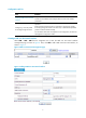
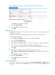
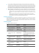
Figure 12 Adding a static route from Device A through interface Tunnel0 to Group 2
• Enter 10.1.3.0 as the destination IP address.
• Select mask 255.255.255.0.
• Select Tunnel0 as the outbound interface.
• Click Apply.
Configuring Device B
The configuration pages of Device B are similar to those of Device A. See the figures provided for
configurations on Device A.
# Configure an IPv4 address and assign the interfaces to security zones. (Details not shown.)
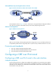
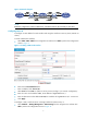
# Create a GRE tunnel interface.
• Select VPN > GRE > GRE from the navigation tree and then click Add.
• Enter 0 in the Tunnel Interface field.
• Enter IP address/mask 10.1.2.2/24.
• Select Trust from the Zone list. (Select a security zone according to your network configuration.)
• Enter the source end IP address 2.2.2.2, the IP address of GigabitEthernet 0/1.
• Enter the destination end IP address 1.1.1.1, the IP address of GigabitEthernet 0/1 on Device A.
• Click Apply.
# Configure a static route from Device B through interface Tunnel0 to Group 1.
• Select Network > Routing Management > Static Routing from the navigation tree and then click
Add.
• Enter 10.1.1.0 as the destination IP address.
• Select mask 255.255.255.0.
• Select Tunnel0 as the outbound interface.
• Click Apply.
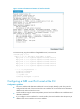
Verifying the configuration
# Log in to the web interface of Device A and then select Device Management > Interface from the
navigation tree. Click the name link of Tunnel0. You can view the status of interface Tunnel0, as shown
in Figure 13.