
R3721-F3210-F3171-HP High-End Firewalls VPN Configuration Guide-6PW101

192
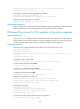
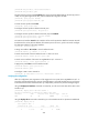
Figure 126 Apply IPsec policy to interface GigabitEthernet 0/1
• Select the policy of map1.
• Click Apply.
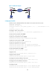
Configuring Device B
NOTE:
The configuration steps on Device B are similar to those on Device A. The configuration pages are not
shown.
# Assign IP addresses for the interfaces and then add them to the target zones. (Details not shown.)
# Define an ACL to permit traffic from subnet 10.1.2.0/24 to subnet 10.1.1.0/24.
• Select Firewall > ACL from the navigation tree, and then click Add.
• Enter 3101 as the ACL number.
• Select the match order of Config.
• Click Apply.
• From the ACL list, select ACL 3101 and click the icon. Then, click Add to enter the ACL rule
configuration page.
• Select Permit from the Operation list.
• Select Source IP Address and enter 10.1.2.0 and 0.0.0.255 respectively in the following fields.
• Select Destination IP Address and enter 10.1.1.0 and 0.0.0.255 respectively in the following fields.
• Click Apply.
# Configure a static route to Host A.
• Select Network > Routing Management > Static Routing from the navigation tree, and then click
Add.
• Enter 10.1.1.0 as the destination IP address.
• Enter 255.255.255.0 as the mask.
• Select GigabitEthernet0/1 as the outbound interface.
• Click Apply.
# Configure an IPsec proposal named tran1.
• Sel
ect VPN > IPSec > Proposal from the navigation tree and then click Add.
• Select Custom mode from the IPSec Proposal Configuration Wizard page.
• Enter tran1 as the name of the IPsec proposal.
• Select Tunnel as the packet encapsulation mode.
• Select ESP as the security protocol.