
R3721-F3210-F3171-HP High-End Firewalls VPN Configuration Guide-6PW101

209
• Deploy a physical link for IPsec service data backup between Firewall A and Firewall B.
• On Firewall A and Firewall B, add the uplink interface to VRRP group 2 and the downlink interface
to VRRP group 1, and assign the virtual IP address 192.168.0.1/24 to VRRP group 2 and the virtual
IP address 10.1.1.1/2 to VRRP group 1.
• Use Firewall A to establish an IPsec tunnel with Router when it works normally, and make sure that
IPsec traffic is switched to Firewall B when Firewall A fails.
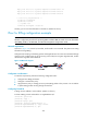
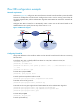
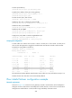
Figure 131 Network diagram
Configuring Firewall A
Assign IPv4 addresses to the interfaces. Make sure that Firewall A, Firewall B, and Router have IP
connectivity between them.
1. Configure stateful failover:
a. Log in to the web interface of Firewall A, select High Reliability > Stateful Failover from the
navigation tree to enter the Stateful Failover Configuration page.
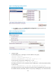
b. Click the Modify Backup Interface button.
c. Select and add GigabitEthernet 0/3 to the Backup Interface(s) list as shown in Figure 132.