
R3721-F3210-F3171-HP High-End Firewalls VPN Configuration Guide-6PW101

29
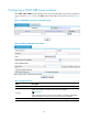
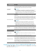
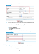
b. Click Add to perform the configurations shown in Figure 26.
c. Enter 192.168.12.0 as the destination IP address.
d. Select mask 255.255.255.0.
e. Select Tunnel0 as the outbound interface.
f. Click Apply.
Figure 26 Adding a static route from Device A through interface Tunnel0 to the branch network
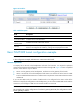
Configuring Device B
1. Configure an IPv4 address for each interface and assign the interfaces to security zones. (Details
not shown.)
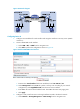
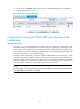
2. Create a GRE over IPv4 tunnel interface:
a. Select VPN > GRE > GRE from the navigation tree.
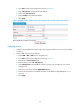
b. Click Add to perform the configurations shown in Figure 27.
c. Enter 0 in the Tunnel Interface field.
d. Enter IP address/mask 192.168.22.2/24.
e. Select Management from the Zone list. (Select a security zone according to your network
configuration.)
f. Select the tunnel source interface GigabitEthernet 0/1.
g. Enter the tunnel destination IP address 11.1.1.1, the IP address of GigabitEthernet 0/1 on
Device A.
h. Click Apply.