
R3721-F3210-F3171-HP High-End Firewalls VPN Configuration Guide-6PW101

30
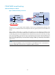
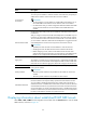
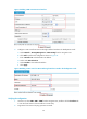
Figure 27 Adding a GRE over IPv4 tunnel interface
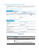
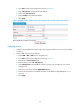
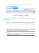
3. Configure a static route from Device B through interface Tunnel0 to the headquarters node:
a. Select Network > Routing Management > Static Routing from the navigation tree.
b. Click Add to perform the configurations shown in Figure 28.
c. Enter 192.168.11.0 as the destination IP address.
d. Select mask 255.255.255.0.
e. Select Tunnel0 as the outbound interface.
f. Click Apply.
Figure 28 Adding a static route from Device B through interface Tunnel0 to the headquarters node
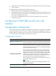
Verifying the configuration
1. On Device A, select VPN > GRE > P2MP from the navigation tree, and then click the Tunnel List tab
to view the tunnel entries. There should be no tunnel entry.
2. Ping Host A from Host B. The ping operation succeeds.