
R3721-F3210-F3171-HP High-End Firewalls VPN Configuration Guide-6PW101


31
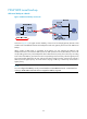
3. On Device A, click Refresh under the tunnel entry list. The P2MP GRE tunnel entry should have
been installed, as shown in Figure 29.
Figure 29 Verifyin
g the configuration result
Configuration example for P2MP GRE tunnel backup at the
headquarters
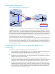
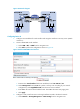
Network requirements
As shown in Figure 30, the headquarters uses two gateways at the egress of the internal network, with
Firewall B for backup. Two GRE tunnels are created on Firewall C, the gateway at the branch, one for
connecting Firewall A and the other for connecting Firewall B. Normally, packets are forwarded along
the tunnel between Firewall A and Firewall C. When a failure occurs along this path, the tunnel between
Firewall B and Firewall C is used to transmit packets.
To meet the above requirements, you need to establish a P2MP GRE tunnel with the branch on both
Firewall A and Firewall B, establish a GRE over IPv4 tunnel between Firewall A and Firewall B, and on
Firewall A, configure the tunnel interface of the GRE over IPv4 tunnel as the backup interface of the P2MP
GRE tunnel interface. Thus, when Firewall A cannot find the corresponding tunnel entry for a packet, it
delivers the packet to Firewall B, which then forwards the packet to Firewall C.
NOTE:
To avoid looping, do not confi
g
ure the tunnel interface of the GRE over IPv4 tunnel as the backup interface
of the P2MP GRE tunnel interface on Firewall B.