
R3721-F3210-F3171-HP High-End Firewalls VPN Configuration Guide-6PW101

32
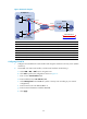
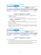
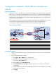
Figure 30 Network diagram
Device Interface IP address
Device
Interface
IP address
Firewall A GE0/1 11.1.1.1/24 Firewall B GE0/1 11.1.1.2/24
GE0/2 10.1.1.1
/
24
GE0/2
10.1.1.2
/
24
GE0/3 192.168.11.1/24
GE0/3
192.168.11.2
/
24
Tunnel0 172.168.1.1/24 Tunnel0 172.168.2.2/24
Tunnel1 192.168.22.1/24
Tunnel1
192.168.22.2/24
Firewall C GE0/1 11.1.1.3
/
24
Firewall
C
Tunnel0
172.168.1.3/24
GE0/2 192.168.12.1/24 Tunnel1 172.168.2.3/24
Configuring Firewall A
1. Configure an IPv4 address for each interface and assign the interfaces to security zones. (Details
not shown.)
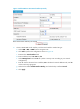
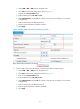
2. Create GRE over IPv4 tunnel interface, with the tunnel interface number being 1:
a. Select VPN > GRE > GRE from the navigation tree.
b. Click Add to perform the configurations shown in Figure 31.
c. Enter 1 in the Tunnel Interface field.
d. Enter IP address/mask 192.168.22.1/24.
e. Select Management from the Zone list. (Select a security zone according to your network
configuration.)
f. Enter the tunnel source IP address 10.1.1.1.
g. Enter the tunnel destination IP address 10.1.1.2.
h. Click Apply.
GE0/2
GE0/1
GE0/1
Firewall A
Firewall B
(Backup gateway)
IPv4 network
Firewall C
GE0/2
GE0/3
GE0/3
GE0/1 GE0/2
Tunnel0
Tunnel0
Tunnel0
Tunnel1
Tunnel1
Tunnel1
Host A
Host B
Host C
GRE P2MP tunnel
GRE over IPv4 tunnel
Headquarters
Branch