
R3721-F3210-F3171-HP High-End Firewalls VPN Configuration Guide-6PW101

428
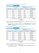
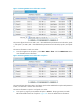
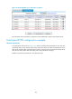
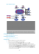
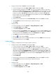
Figure 322 Network diagram
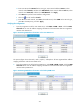
Device Interface IP address
Device
Interface IP address
Hub 1 GE0
/
1 192.168.1.1
/
24
Spoke 1
GE0
/
1
192.168.1.3
/
24
Tunnel1 10.0.1.1/24 GE0/2 10.0.2.1/24
Hub 2 GE0
/
1 192.168.1.2
/
24
Tunnel1 10.0.1.3
/
24
Tunnel1 10.0.1.2/24
Spoke 2
GE0
/
1
192.168.1.4
/
24
Main server GE0/1 192.168.1.22/24 GE0/2 10.0.3.1/24
Backup server GE0
/
1 192.168.1.33/
/
24
Tunnel1 10.0.1.4
/
24
RADIUS server
192.168.1.11
/
24
NOTE:
See the configuration pages provided in the full mesh network configuration example for references.
Configuring the main VAM server
See "Configuring the main VAM server."
Configuring the backup VAM server
See "Configure the backup VAM server."
Configuring Hub 1
1. Configure IP addresses for the interfaces. (Details not shown)
2. Configure tunnel interface Tunnel1 for VPN domain vpn1:
a. From the navigation tree, select VPN > DVPN > Client, and then click Add.
b. Select the tunnel encapsulation mode UDP. Enter tunnel interface number 1. Enter the IP
address/mask 10.0.1.1/24. Select security zone Management for the tunnel interface. Select
the tunnel source interface GigabitEthernet0/1. Enter the VPN domain name vpn1. Enter the
VAM server address 192.168.1.22. Enter the backup VAM server address 192.168.1.33.
Enter the VAM client username dvpn1hub1. Enter the VAM client password dvpn1hub1. Enter
the VAM client pre-shared key 123.