
R3721-F3210-F3171-HP High-End Firewalls VPN Configuration Guide-6PW101

457
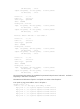
--- 10.0.5.1 ping statistics ---
5 packet(s) transmitted
5 packet(s) received
0.00% packet loss
round-trip min/avg/max = 4/4/5 ms
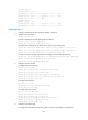
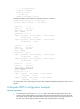
# Display the DVPN tunnel information of interface Tunnel 2 on Spoke 2.
[Spoke2] display dvpn session interface tunnel 2
Interface: Tunnel2 VPN name: 2 Total number: 3
Private IP: 10.0.2.1
Public IP: 192.168.1.1
Session type: spoke-Hub
State: SUCCESS
Holding time: 1h 10m 0s
Input: 451 packets, 450 data packets, 1 control packets
435 multicasts, 0 errors
Output: 453 packets, 447 data packets, 6 control packets
430 multicasts, 0 errors
Private IP: 10.0.2.2
Public IP: 192.168.1.2
Session type: spoke-Hub
State: SUCCESS
Holding time: 0h 1m 50s
Input: 242 packets, 241 data packets, 1 control packets
231 multicasts, 0 errors
Output: 251 packets, 241 data packets, 7 control packets
225 multicasts, 0 errors
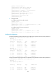
Private IP: 10.0.2.3
Public IP: 192.168.1.5
Session type: spoke-spoke
State: SUCCESS
Holding time: 0h 0m 0s
Input: 1 packets, 0 data packets, 1 control packets
0 multicasts, 0 errors
Output: 1 packets, 0 data packets, 1 control packets
0 multicasts, 0 errors
The output shows that a spoke-spoke tunnel has been established dynamically between Spoke 2 and
Spoke 3.
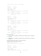
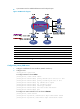
Hub-spoke DVPN configuration example
Network requirements
• In the hub-spoke network shown in Figure 329, data is forwarded along hub-spoke tunnels. The
primary and secondary VAM servers manage and maintain information about the nodes. The AAA
server takes charge of VAM client authentication and accounting. With each being the backup of
the other, the two hubs perform data forwarding and routing information exchange.