
R3721-F3210-F3171-HP High-End Firewalls VPN Configuration Guide-6PW101

40
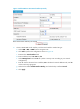
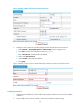
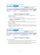
Figure 41 Verifying the configuration result on Firewall A
3. Perform the same operations on Firewall B and you can see that there is no P2MP GRE tunnel
established on Firewall B.
4. Cut off the tunnel link between Firewall A and Firewall C:
a. On Firewall C, select Device Management > Interface from the navigation tree and then click
the icon of interface Tunnel0.
b. Click the Disable button to shut down interface Tunnel0.
5. After the tunnel aging time (10 seconds in this example) elapses, refresh and view the tunnel entry
information on Firewall A.
There should be no tunnel entry any more.
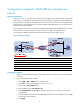
6. Ping Host A from Host C. The ping operation succeeds. Refresh and view the P2MP GRE tunnel
information on Firewall B again. You can see that a P2MP GRE tunnel is established on Firewall B,
as shown in Figure 42.
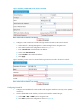
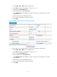
Figure 42 Verifyin
g the configuration result on Firewall B
The information indicates that:
• After the link between Firewall A and Firewall C went down, the tunnel entry aging timer started to
work, and after the timer expired, the tunnel entry on Firewall A was removed.
• After Firewall C sent a packet to Firewall B, a tunnel entry to the branch network was generated on
Firewall B, and packets to the branch network were forwarded through Firewall B