
R3721-F3210-F3171-HP High-End Firewalls VPN Configuration Guide-6PW101

46
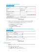
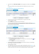
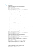
2. On Firewall A, select VPN > GRE > P2MP from the navigation tree and then click the Tunnel List
tab.
You can see information about the P2MP GRE tunnels established on Firewall A, as shown
in Figure 50.
Figure 50 Verifyin
g the configuration result on Firewall A (1)
3. On Host B, specify Firewall B as the default gateway. Ping Host A from Host B.
The ping operation succeeds.
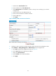
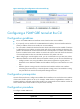
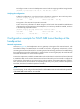
4. Click the Refresh button under the tunnel list of Firewall A.
You can see that another P2MP tunnel entry is generated on Firewall A, as shown in Figure 51.
Fire
wall A prefers the tunnel entry with a smaller GRE key value. Packets are forwarded to hosts on
the branch network through Firewall B.
Figure 51 Verifying the configuration result on Firewall A (2)
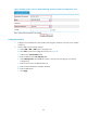
5. Cut off the tunnel link between Firewall A and Firewall B:
a. Select Device Management > Interface from the navigation tree of Firewall B. Click the icon
of interface Tunnel0.
b. Click the Disable button to shut down interface Tunnel0.
6. On Host B, specify Firewall C as the default gateway. After the tunnel entry corresponding to
Firewall B ages out, ping Host A from Host B.
The ping operation succeeds.
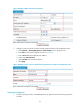
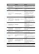
7. View P2MP GRE tunnel entries on Firewall A again, the information is shown as Figure 52. The
information indicates that after the link between Firewall A and Firewall B is down, Firewall A has
only the tunnel entry that uses Firewall C for forwarding of packets to the branch network.