
R3721-F3210-F3171-HP High-End Firewalls VPN Configuration Guide-6PW101

54
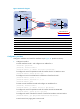
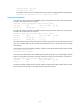
# Configure a static route to the headquarters network with the outgoing interface being Tunnel0
and priority value being 1.
[FirewallC] ip route-static 192.168.11.0 255.255.255.0 tunnel 0 preference 1
# Create tunnel interface Tunnel 1 and configure an IP address for it.
[FirewallC] interface tunnel 1
[FirewallC-Tunnel1] ip address 172.168.2.3 255.255.255.0
# Configure the tunnel encapsulation mode of interface Tunnel1 as GRE over IPv4.
[FirewallC-Tunnel1] tunnel-protocol gre
# Configure the source and destination IP addresses of interface Tunnel1.
[FirewallC-Tunnel1] source 11.1.1.3
[FirewallC-Tunnel1] destination 11.1.1.2
[FirewallC-Tunnel1] quit
# Configure a static route to the headquarters network with the outgoing interface being Tunnel1
and priority value being 10. This makes the priority of this route lower than that of the static route
of interface Tunnel0, making sure that Firewall C prefers the tunnel between Firewall A and
Firewall C for packet forwarding.
[FirewallC] ip route-static 192.168.11.0 255.255.255.0 tunnel 1 preference 10
NOTE:
If the link between Firewall A and Firewall C
g
oes down, Firewall C will sense the failure and try to send
packets to Firewall B, initiating the establishment of the tunnel between Firewall B and Firewall C. Only
then can Firewall B learn the tunnel entry.
If Firewall A and Firewall C are directly connected, confi
g
urin
g
a static route on Firewall C can make sure
that Firewall C senses the failure of the link between Firewall A and Firewall C. If the two are not directl
y
connected, you need to use either of the following methods to achieve the effect:
• Configure dynamic routing on Firewall A, Firewall B, and Firewall C.
• On Firewall C, associate the static route with a track entry, so as to use the track entry to track the status
of the static route. For details about track entry, see
High Availability Configuration Guide
.
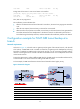
Verifying the configuration
# Ping Host A from Host C. The ping operation succeeds. View the tunnel entries on Firewall A and
Firewall B.
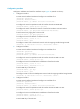
[FirewallA] display gre p2mp tunnel-table interface tunnel 0
Dest Addr Mask Tunnel Dest Addr Gre Key
192.168.12.0 255.255.255.0 11.1.1.3
[FirewallB] display gre p2mp tunnel-table interface tunnel 0
Dest Addr Mask Tunnel Dest Addr Gre Key
The output shows that Firewall A has a tunnel entry to the branch network. Packets to the branch network
are forwarded through Firewall A.
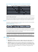
# On Firewall C, shut down interface Tunnel0 to cut off the tunnel link between Firewall A and Firewall
C.
[FirewallC] interface tunnel 0
[FirewallC-Tunnel0] shutdown
# After the tunnel entry aging time (20 seconds in this example) elapses, view the tunnel entry
information on Firewall A.
[FirewallA] display gre p2mp tunnel-table interface tunnel 0