
R3721-F3210-F3171-HP High-End Firewalls VPN Configuration Guide-6PW101

55
Dest Addr Mask Tunnel Dest Addr Gre Key
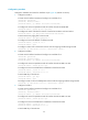
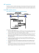
# Ping Host A from Host C. View tunnel entries on Firewall B:
[FirewallB] display gre p2mp tunnel-table interface tunnel 0
Dest Addr Mask Tunnel Dest Addr Gre Key
192.168.12.0 255.255.255.0 11.1.1.3
Then, Host A can ping Host C.
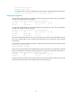
The verification process indicates that:
• After the link between Firewall A and Firewall C went down, the tunnel entry aging timer started to
work.
• After the timer expired, the tunnel entry on Firewall A was removed.
• After Firewall C sent a packet to Firewall B, a tunnel entry to the branch network was generated on
Firewall B. Packets from the headquarters to the branch network are delivered by Firewall A to
Firewall B through the backup interface, and then Firewall B forwards these packets to the branch.
Configuration example for P2MP GRE tunnel backup at a
branch
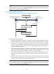
Network requirements
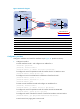
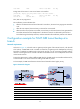
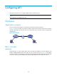
As shown in Figure 43, a branch uses two gateways at the egress of the internal network, with Firewall
C for backup. A P2MP GRE tunnel is created on Firewall A, the gateway at the headquarters, allowing
Firewall A to establish two GRE tunnels to the branch network, one for connecting Firewall B and the
other for connecting Firewall C. Firewall A decides which GRE tunnel to use to send packets to the hosts
on the branch network.
To meet the requirements, configure different GRE keys for the GRE tunnels on Firewall B and Firewall C,
so that Firewall A can choose a tunnel according to the GRE key values.
In this example, the GRE tunnel between Firewall A and Firewall B has a higher priority.
Figure 55 Network diagram
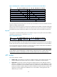
Device Interface IP Address
Device
Interface
IP Address
Firewall A GE0/1 11.1.1.1/24 Firewall B GE0/1 11.1.1.2/24
GE0/2 172.17.17.1/24
GE0/2
192.168.1.2
/
24
Tunnel0 192.168.22.1/24
Tunnel0
192.168.22.2/24
Firewall C GE0/1 11.1.1.3/24 Firewall C Tunnel0 192.168.22.3/24
GE0/2 192.168.1.3
/
24