
R3721-F3210-F3171-HP High-End Firewalls VPN Configuration Guide-6PW101

68
Verifying the configuration
Execute the ping ipv6 2000:0:404:402:: command on Firewall A. The ping operation should be
successful.
# Execute the display session table verbose command on Firewall B to display the established sessions.
[FirewallB] display session table verbose
Initiator:
Source IP/Port : 0006:0:ff06:0606:0200::/32768
Dest IP/Port : 2000:0:0404:0402::/43982
VPN-Instance/VLAN ID/VLL ID:
Responder:
Source IP/Port : 4.4.4.2/0
Dest IP/Port : 6.6.6.2/43982
VPN-Instance/VLAN ID/VLL ID:
Pro: ICMPv6(58) App: unknown State: ICMP-CLOSED
Start time: 2010-12-21 16:06:44 TTL: 14s
Root Zone(in):
Zone(out): Management
Received packet(s)(Init): 5 packet(s) 520 byte(s)
Received packet(s)(Reply): 5 packet(s) 420 byte(s)
Total find: 1
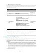
An IPv4 host initiates communication with an IPv6 host
Network requirements
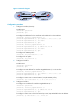
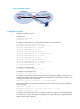
As shown in Figure 62, Firewall A is in an IPv6 network and has an address of 6:0:ff06:606:200::, and
Firewall C is in an IPv4 network and has an address of 4.4.4.2. Firewall C wishes to communicate with
Firewall A.
For Firewall C to communicate with Firewall A, enable AFT and configure DNS64 and IVI prefixes and
4to6 AFT policies on Firewall B.
Figure 62 Network diagram
Configuration procedure
1. Configure Firewall B (the AFT):
# Enable IPv6.
<FirewallB> system-view
[FirewallB] ipv6
# Configure IP addresses for the interfaces and enable AFT on the interfaces.
[FirewallB] interface gigabitethernet 0/1
[FirewallB-GigabitEthernet0/1] ipv6 address 6:0:ff06:606:100::/64