
HP StorageWorks SAN Director Installation Guide (A7393-90009, May 2007)

Installing FRUs122
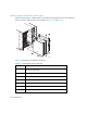
Locating AC power inlets on the SAN Director
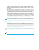
Figure 33 and Table 36 identify the locations of the AC power connectors and AC power switches
on the SAN Director chassis. In order for the power supply units to function correctly, the AC power
connector cables must be plugged in to the AC power connectors and the AC power switches must
be turned on.
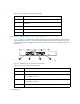
Figure 33 Chassis AC power connectors and switches
Table 36 AC power connectors and switches
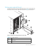
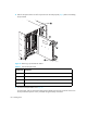
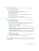
3 Handle (displayed in an unlocked position)
4 Filler panel
5Lip
6 AC power connector label (2 per chassis)
7 Power Supply unit label (4 per chassis)
Table 35 Power Supply components (continued)
Component Description
Number Description
1 AC power switch (controls the power for Power Supplies 1 and 3)
2 AC power connector (connects to the AC power cables for
Power Supplies 1 and 3
3 AC power connector (connects to the AC power cables for
Power Supplies 2 and 4)
4 AC power switch (controls the power for Power Supplies 2 and 4)
200-240 VAC 12A 50-60 Hz
200-240 VAC 12A 50-60 Hz
1 2 3 4
25036a