
HP StorageWorks SAN Director Installation Guide (A7393-90009, May 2007)

SAN Director installation guide 127
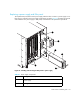
10. For the FC2-16, FC4-16, FC4-32 and FC4-16IP port blades: Lever both ejectors open
simultaneously to approximately 45 degrees and pull the port blade out of the chassis.
For the FC4-48 port blade: Open the ejectors. Pull the port blade out of the chassis using the
ejectors.
If the port blade is not being replaced by another HP StorageWorks port blade, install a filler
panel to ensure correct cooling of the chassis and protection from dust. See ”Removing and
replacing port blade filler panels” on page 128 for instructions.
Installing a port blade
Use these steps to install a port blade.
CAUTION: Make sure to gently apply pressure to the port blade, in order to properly seat the
blade all the way into the slot. Applying excessive pressure may damage the VHDM connectors on
the Director’s backplane.
B
1. If a port blade filler panel is installed in the slot, you must remove it. See ”Removing port blade
filler panels” on page 129.
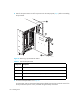
2. Orient the port blade so that the ports are at the front of the chassis and the flat side of the port
blade is on the left.
3. Open the ejectors to approximately 45 degrees, align the flat side of the port blade inside the
upper and lower rail guides in the slot (see ”Removing a port blade with sliders” on page 126),
and slide the port blade into the slot, with slight pressure to the left, until it is firmly seated.
4. Close the ejectors by pushing the handles toward the center of the port blade until the ejectors
lock. The levering action of the handles seats the port blade in the slot.
5. For the FC2-16, FC4-16, FC4-32 port blades, tighten the thumb screw inside each handle using
the Phillips screwdriver.
6. For the FC2-16, FC4-16, FC4-32 port blades, turn the port blade on by sliding the slider switch in
the top ejector up, covering the thumb screw.
7. Verify that the power LED on the port blade displays a steady green light (it might require a few
seconds to turn on). If it does not turn on, ensure that the port blade is firmly seated.
NOTE: The LED patterns might temporarily change during POST and other diagnostic tests.
8. Install SFP transceivers and cables in the port blade, as required.
9. Group and route the cables as desired (see ”More tips on managing cables” on page 129).