
HP StorageWorks SAN Director Installation Guide (A7393-90009, May 2007)


Installing the optional B-Series MP Router blade138
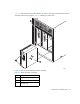
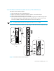
Table 40 identifies B-Series MP Router blade components outlined in Figure 38.
The Fibre Channel ports are numbered from bottom to top, in eight-port groups, and are numbered
on the faceplate.
Configure FCIP and Fibre Channel Routing Services and enable the ports
The ports on the B-Series MP Router blade are initially set to persistently disabled.
If you want to enable the FC ports as a standard E_Port or F_port use the
portcfgpersistentenable command to enable the ports.
If you are using the FC ports as EX_Ports you must configure the Fibre Channel Routing Services
feature prior to enabling the ports.
The GbE ports can only be used once you have configured FCIP and enabled the VE_Ports.
See the HP StorageWorks Fabric OS administrator guide for detailed instructions on configuring the
Fibre Channel Router ports and GbE ports on the B-Series MP Router blade.
Cable the B-Series MP Router blade
To complete the switch configuration:
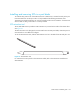
1. Install the SFP transceivers in the Fibre Channel and GbE ports, as required.
a. Remove the rubber plugs from the ports to be used.
b. Position a transceiver so that it is oriented correctly and insert it into a port until it is firmly
seated and the latching mechanism clicks.
For instructions specific to the type of transceiver, see the transceiver manufacturer’s
documentation.
NOTE: The transceivers are keyed to ensure correct orientation. If a transceiver does not install
easily, ensure that it is correctly oriented.
c. Repeat Steps a and b for the remaining ports, as required.
Table 40 Identifying B-Series MP Router blade components
1 Blade power LED
7 ON/OFF slider switch
2 Blade status LED 8 FC port
3 Fibre Channel port 9 GbE ports (2)
4 Upper ejector 10 Thumb screw
5 Thumb screw 11 Lower ejector
6 FC port status LED 12 Fibre Channel port status LED
13 GbE port status LED