
HP StorageWorks SAN Director Installation Guide (A7393-90009, May 2007)

Installing and configuring the 4/256 SAN Director48
NOTE: Cables can be routed down through the cable management comb or through the holes in
the sides of the chassis. If the cables will be routed down through the cable management comb,
allow adequate space below the chassis for cable management.
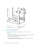
Attaching the upper rack mount bracket assemblies to the chassis
Use these steps to attach the upper rack mount brackets to the chassis. The upper rack mount
bracket assemblies consist of the following:
• One right flat upper rack mount bracket attached to an L-shaped bracket
• One left flat upper rack mount bracket attached to an L-shaped bracket
NOTE: To compete this procedure, you must first detach the L-shaped brackets from the upper rack
mount bracket assemblies.
1. Use a Phillips head screwdriver to remove the screws securing the left and right upper rack mount
brackets to the L-shaped brackets. Detach the L-shaped brackets from the assembly and put them
aside.
NOTE: You reinstall the L-shaped brackets to the rack rails in step 5.
2. Save the screws for attaching the bracket assemblies to the chassis (see step 1 in the section
”Securing the chassis to the rails” on page 51).
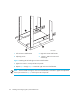
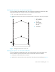
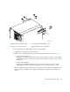
3. Use four #10-32 x 5/16 inch screws to secure the right and left flat upper rack mount brackets to
the chassis. See Figure 8.
NOTE: Orient the slotted holes in the brackets toward the blower side of the chassis (see Figure 8
for orientation).