
HP StorageWorks SAN Director Installation Guide (A7393-90009, May 2007)

SAN Director installation guide 55
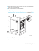
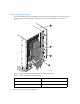
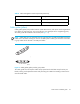
4. Loosen the clamping screw on each retainer, insert the power cords through the retainers into the
power receptacles on the 4/256 SAN Director, and tighten the clamping screws. The power
cords are designed to bend to the left, so each should route to an opposite side of the chassis.
5. Ensure that the power cord has a minimum service loop of 6 inches available at the connection
to the switch and is routed so that it is not exposed to stress.
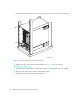
6. Connect the power cords to a power source with voltage of 200 to 240 VAC, 47 to 63 Hz.
7. Flip both AC power switches to 1. The AC power switches light up green when switched on and
power is supplied.
The 4/256 SAN Director automatically performs a power-on self-test (POST) by default each time
it is powered on. POST takes approximately 10 minutes and is complete when indicator light
activity returns to the standard state. For information about LED patterns, refer to ”Monitoring
system components” on page 63.
You can bypass POST by using the fastBoot command. You can also disable POST for
successive reboots on the switch using the diagDisablePost command.
CAUTION: To prevent a potential IP address conflict, do not connect the 4/256 SAN Director to
the network until the IP addresses are configured. Refer to ”Setting initial configuration parameters”
on page 61 for additional information. Allow the 4/256 SAN Director to run for 10 minutes
(minimum) to complete POST after powering on before you power off.
Establishing a serial connection
Initial communication to a 4/256 SAN Director switch requires a serial connection. Use these steps
to establish a serial connection and log in to the Director:
1. Verify that the 4/256 SAN Director is powered on and that POST is complete by verifying that
all power LED indicators on the port blades and CP4 cards are displaying a steady green light.
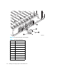
2. Use the serial cable provided with the 4/256 SAN Director to connect the console port on the
active CP4 card to a computer workstation.
The console port is the second serial port from the top of the CP4 card; the active CP4 card is
indicated by an illuminated (blue) LED. The “Active CP” LED in the standby CP card should be off
(not illuminated).
The console port is intended primarily for use during the initial setting of the IP address and for
service purposes. If necessary, the adapter on the serial cable can be removed to allow for an
RJ-45 serial connection.
3. Access the Director using a terminal emulator application (such as HyperTerminal on Windows
95, 2000, or NT or TERM in a UNIX environment).
4. Disable any serial communication programs running on the workstation (such as synchronization
programs).