
HP StorageWorks SAN Director Installation Guide (A7393-90009, May 2007)


SAN Director installation guide 97
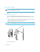
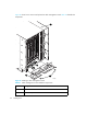
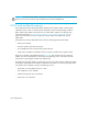
Figure 27 identifies the locations for the AC Power Connectors and AC Power Switches on the
chassis.
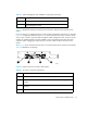
If you are removing or installing the lower mounting cable management comb (shown on the left in
Figure 26 on page 96) while the Director is on, you must remove the AC power connector cables
one at a time in order to route the cables through the cable management comb. If only two power
supplies are installed and they are both installed in slots corresponding to the same AC power
connector cable, unplugging a single AC power connector cable can power down the entire
chassis.
See Figure 27 for the locations of the AC power connectors and AC power switches on the chassis.
Table 28 identifies the components.
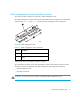
Figure 27 Chassis AC power connectors and switches
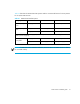
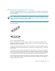
3 Screws (2 per cable management comb)
4 Cable management comb
Table 28 AC power connectors and switches
Number Description
1 AC power switch (controls the power for power supplies 1 and 3)
2 AC power connector (connects to the AC power cables for power supplies
1 and 3
3 AC power connector (connects to the AC power cables for power supplies
2 and 4)
4 AC power switch (controls the power for power supplies 2 and 4)
Table 27 Cable management comb installation components (continued)
Number Description
200-240 VAC 12A 50-60 Hz
200-240 VAC 12A 50-60 Hz
1 2 3 4
25036a