
HP StorageWorks SAN Director Installation Guide (A7393-90009, May 2007)

Installing FRUs98
Removing a cable management comb
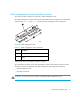
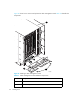
Use these steps to remove the cable management comb (shown in Figure 26 on page 96):
1. If the Director is not operating: Remove the AC power connector cables and continue with
step 2, then remove the cable management comb from the chassis.
If the Director is operating: Remove any cables from the comb, except the AC power connector
cables.
Orient comb as shown in ”Installing a cable management comb” on page 96, aligning thc
holes on the comb with the holes on the chassis. Then position and tighten the two screws. The
cable management comb is installed
2. Unscrew the two screws holding the comb to the chassis (see Figure 26 for location of screws)
and save them for reuse.
3. With the AC power connector cables still plugged in, detach the cable management comb
approximately five inches away from the chassis.
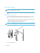
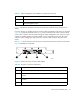
4. Switch the AC power switch off (for example, item 1 in Figure 27) and remove the corresponding
AC power connector cable (for example, item 2 in Figure 27) from the chassis. Route the AC
power connector cable through the comb.
5. Plug the AC power connector cable back into the connector on the chassis, and switch the AC
power switch on.
6. Repeat step 4 and step 5 for the other AC power switch and AC power connector cable.
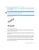
7. Pull the cable management comb out and up, making sure not to loosen or remove any cables.
The cable management comb is now removed from the Director chassis.
Reinstalling a cable management comb
Use these steps to reinstall the cable management comb (see Figure 26 on page 96):
1. If the Director is not operating: Remove any cables and orient the comb as shown in Figure 24
on page 80, aligning the holes on the comb with the holes on the chassis. Then position and
tighten the two screws. The cable management comb is installed.
If the Director is operating, go to step 2.
2. Switch the AC power switch off (for example, item 1 in Figure 27) and remove the corresponding
AC power connector cable (for example, item 2 in Figure 27) from the chassis. Route the AC
power connector cable through the comb.
3. Plug the AC power connector cable back into the connector on the chassis, and switch the AC
power switch on.
4. Repeat step 2 and step 3 for the other AC power switch and AC power connector cable.
5. Position and tighten the two screws to secure the cable management comb to the chassis.
6. Arrange the cables through or along the cable management comb as required. Route the AC
power connector cables out of each side of the chassis.