H3C LSW1FC4P0 Interface Card for S5820X-28C Ethernet Switches Installation Manual Manual Version: T2-0804AQ-5PW102
Copyright © 2011, Hangzhou H3C Technologies Co., Ltd. and its licensors. All Rights Reserved No part of this manual may be reproduced or transmitted in any form or by any means without prior written consent of Hangzhou H3C Technologies Co., Ltd. Trademarks H3C, Aolynk, H3Care, TOP G, IRF, NetPilot, Neocean, NeoVTL, SecPro, SecPoint, SecEngine, SecPath, Comware, Secware, Storware, NQA, VVG, V2G, VnG, PSPT, XGbus, N-Bus, TiGem, InnoVision and HUASAN are trademarks of Hangzhou H3C Technologies Co., Ltd.
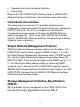
Table of Contents 1 Overview ...................................................................................... 5 Hardware ..................................................................................... 5 LSW1FC4P0 Card LEDs ........................................................6 Flex Ports ................................................................................ 6 Management Port ...................................................................7 Maintenance Button .....................
Resetting User Accounts (Option 3) ..........................................30 Copying Log Files (Option 4) .....................................................30 Removing the Switch Configuration (Option 5) ..........................30 Remaking the File System (Option 6) ........................................30 Resetting the Switch Mode (Option 7) .......................................31 Updating the Boot Loader (Option 8) .........................................31 5 Specifications ..................
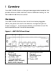
1 Overview The LSW1FC4P0 Card is a four-port converged switch module that provides Ethernet LAN and Fibre Channel SAN connectivity for the H3C S5820X-28C Ethernet switch. Hardware The LSW1FC4P0 Card has four Small Form-factor pluggable (SFP+) flex ports and one RJ-45 Ethernet management port as shown in Figure 1. A maintenance button is available to reset the card or place the card in maintenance mode. Figure 1.
LSW1FC4P0 Card LEDs The LSW1FC4P0 card has a Power LED and a System LED. The LED indications are shown in Table 1: Table 1. Interface Card LED Indications Power LED System LED Status Steady green Steady Maintenance mode Slow flash (1.5Hz) Normal operation Quick flash (6Hz) System boot Steady red Power failure Off Power is off Off System failure or the power is off Flex Ports The flex ports are labeled 1−4 (Ext0:1, Ext2:1, Ext3:2, Ext4:3) and are served by SFP+ optical transceivers.
LED. This shows that the port is properly connected and able to communicate with its attached devices. The Logged-In LED remains illuminated as long as the port is initialized or logged in. If the port connection is broken or an error occurs that disables the port, the Logged-In LED is extinguished. The flex port Activity LED indicates that data is passing through the port. Each frame that the port transmits or receives illuminates this LED for 50 milliseconds.
green and the System LED flashes at 6Hz. When the reset is complete, the System LED flashes as 1.5Hz. Placing the Interface Card in Maintenance Mode Placing the interface card in maintenance mode is disruptive. Consider rerouting critical data traffic before using maintenance mode. To place the interface card in maintenance mode, do the following: 1. Press and hold the maintenance button with a pointed tool for approximately 10 seconds.
• • Operational and environmental statistics Online help Refer to the H3C LSW1FC4P0 Interface Card for S5820X-28C Ethernet Switches QuickTools User Guide for more information. Command Line Interface The command line interface (CLI) provides monitoring and configuration functions by which the administrator can manage the LSW1FC4P0 Card. The CLI is available over the Ethernet management port connection or through the S5820X Ethernet switch (see page 20).
2 Installation Caution To prevent damaging the LSW1FC4P0 card, avoid touching the components on the card during installation or removal. Wear an ESD-preventive wrist strap and ESD-preventive gloves when installing or removing an LSW1FC4P0 card. Installing the interface card involves the following steps: 1. Install the LSW1FC4P0 card in the Ethernet switch. 2. Install the transceivers. 3. Configure the workstation. 4. Connect the workstation to the LSW1FC4P0 card. 5. Configure the LSW1FC4P0 card. 6.
5. Configure the S5820X-28C Ethernet card, as needed. Figure 2. Install an Interface Card 1. Ejector levers To remove the LSW1FC4P0 Card, do the following: 1. Loosen the captive screws on the LSW1FC4P0 card until all spring pressure is released. 2. Rotate the card ejector levers outward to unseat the LSW1FC4P0 Card from the backplane. 3. Gently pull the LSW1FC4P0 Card out of the slot. 4. If you are not replacing the card, install the filler panel to ensure proper ventilation in the Ethernet switch.
Installing Transceivers This product uses Class 1 laser optical transceivers to communicate over the fiber optic conductors. The U.S. Department of Health and Human Services (DHHS) does not consider Class 1 lasers to be hazardous. The International Electrotechnical Commission (IEC) 825 Laser Safety Standard requires labeling in English, German, Finnish, and French stating that the product uses Class 1 lasers.
Configuring the Workstation The workstation requirements are described in Table 2. Table 2. Workstation Requirements Component Requirement Operating System • • • • • Memory 512 MB or more; 1 GB recommended Processor 1GHz or faster Internet Browser Microsoft® Internet Explorer® 6.0 or later Windows 2003 and XP SP1/SP2 Solaris 9, 10, and 10 x86 Red Hat® Enterprise Linux 4 and 5 SUSE™ Linux Enterprise Server 9 and 10 Mac® OS X 10.4 and 10.5 Netscape Navigator® 6.0 and later Mozilla™ 1.
For a Windows workstation, do the following: 1. Click the Start button and choose Settings>Control Panel>Network and Dial-Up Connections. 2. Choose Make New Connection. 3. Click the Connect to a private network through the Internet radio button, then click the Next button. 4. Enter 10.0.0.253 for the IP address. For a Linux or Solaris workstation, open a command window and enter the following command where (interface) is your interface name: ifconfig (interface) ipaddress 10.0.0.253 netmask 255.255.255.
• • Indirect Ethernet connection from the management workstation to the interface card RJ-45 management port through an Ethernet switch or a hub. This requires a 10/100 Base-T straight cable. Direct Ethernet connection from the management workstation to the interface card RJ-45 management port. This requires a 10/100 Base-T cross-over cable. Configuring the LSW1FC4P0 Card You can configure the interface card using the CLI or QuickTools.
5. Open an Internet browser again and log in with the new IP address. Refer to the H3C LSW1FC4P0 Interface Card for S5820X-28C Ethernet Switches QuickTools User Guide for more information. To configure the interface card using the CLI, do the following: 1. Open a command window according to the type of workstation and connection. 2. Open a Telnet session with the default switch IP address (10.0.0.1) and log in to the switch with the default account name and password (admin/password). telnet 10.0.0.
Configuring Flex Ports All flex ports are configured at the factory as Fibre Channel transparent fabric ports (TF_Port). Furthermore, each internal TH_Port is mapped to every flex port. To reconfigure a port as a converged enhanced Ethernet port (PT_Port), you must remove the mapping for the selected port and change the corresponding internal port type to PT_Port also.
7. Select the corresponding internal port in the faceplate display. For example, if you are changing flex port Ext1:0, select internal port Int1:4. 8. Select Port>Port Properties to open the Port Properties dialog box. 9. Select PT_Port from the Configured Type drop-down list and click OK. Refer to the H3C LSW1FC4P0 Interface Card for S5820X-28C Ethernet Switches QuickTools User Guide for more information. In the CLI, do the following: 1. Enter the Admin Start and Config Edit commands.
PrimaryTFPortMap [0,1,2,3 H3C (admin-config) #> set config port 7 . . . PrimaryTFPortMap [0,1,2,3 ]0,2,3 ]0,2,3 3. Enter the Set Config Port command for the flex port (Ext2:1) and the corresponding internal port (Int2:5) and change the PortType to PT. H3C (admin-config) #> set config port 1 . . . PortType (PT,TF) [TF ] PT H3C (admin-config) #> set config port 5 . . . PortType (PT,TH) [TH ] PT 4. Enter the Config Save and Config Activate commands to save and activate the new configuration.
Managing the LSW1FC4P0 Card through the S5820-28C Ethernet Switch Enter the following command in user view in the switch CLI to open the LSW1FC4P0 card CLI: oap connect slot slot-number system system-name You can now enter LSW1FC4P0 CLI commands. To return to the Ethernet switch CLI, press Ctrl+k. Cabling Devices to the LSW1FC4P0 Card Connect cables to the SFP transceivers and their corresponding devices, and then energize the devices. Device host bus adapters can have SFP (or SFF) transceivers.
3 Installing LSW1FC4P0 Card Firmware The LSW1FC4P0 card has its own firmware apart from the S5820X-28C Ethernet switch. To install new firmware on the LSW1FC4P0 card, you can use the CLI or the QuickTools web applet. You can load and activate firmware upgrades on an operating switch without disrupting data traffic or re-initializing attached devices. If you attempt to perform a non-disruptive activation without satisfying the following conditions, the activation will fail.
After upgrading firmware that includes changes to QuickTools, an open QuickTools session may indicate that the firmware is not supported. This means the new firmware is not supported by the previous QuickTools version. To correct this, close the QuickTools session and the browser window, then open a new QuickTools session. Using QuickTools to Install Firmware To install firmware using QuickTools, do the following: 1. In the faceplate display, open the Switch menu and select Load Firmware. 2.
Refer to the H3C LSW1FC4P0 Interface Card for S5820X-28C Ethernet Switches Command Line Interface Guide for information about the CLI commands. One-Step Firmware Activation The Firmware Install and Image Install commands download the firmware image file from an FTP or TFTP server to the interface card, unpacks the image file, and performs a disruptive activation in one step.
2. Enter your choice for the file transfer protocol with which to download the firmware image file. FTP requires a user account and a password; TFTP does not. FTP or TFTP : ftp 3. Enter your account name on the remote host (FTP only) and the IP address of the remote host. When prompted for the source file name, enter the path for the firmware image file. User Account : johndoe IP Address : 10.0.0.254 Source Filename : 9.0.xx.xx_flcn About to install image. Do you want to continue? [y/n] y 4.
Custom Firmware Installation A custom firmware installation downloads the firmware image file from an FTP or TFTP server to the interface card, unpacks the image file, and resets the interface card in separate steps. This allows you to choose the type of reset and whether the activation will be disruptive (Reset Switch command) or non-disruptive (Hotreset command). The following example illustrates a custom firmware installation with a non-disruptive activation. 1.
4. Wait for the unpack to complete. image unpack command result: Passed 5. A message will prompt you to reset the interface card to activate the firmware. Enter the Hotreset command to attempt a nondisruptive activation.
4 Recovering an LSW1FC4P0 Card Using Maintenance Mode The LSW1FC4P0 card can become inoperable or unmanageable for the following reasons: • • • • Firmware becomes corrupt IP address is lost Configuration becomes corrupt Password is forgotten In these specific cases, you can recover the LSW1FC4P0 card using maintenance mode. Maintenance mode temporarily returns the interface card IP address to 10.0.0.
3. Enter the maintenance mode account name (prom) and password (prom), and press Enter. Switch login: prom Password: xxxx 4. The maintenance menu displays several recovery options. To select a recovery option, press the corresponding number (displayed in option: field) on the keyboard and press Enter.
Installing a Firmware Image (Option 1) The Image Unpack option unpacks and installs new firmware when the current firmware has become corrupt. Before using this option, you must load the new firmware image file onto the interface card. To install new firmware using this option: 1. Place the switch in maintenance mode. See the procedure for maintenance mode in “4 Recovering an LSW1FC4P0 Card Using Maintenance Mode” page 27. 2. Use FTP to load a new firmware image file onto the switch.
Resetting User Accounts (Option 3) The Reset User Accounts to Default option restores the password for the Admin account name to the default (password) and removes all other user accounts from the switch. Copying Log Files (Option 4) The Copy Log Files option copies all log file buffers to a file named logfile on the interface card. You can use FTP to download this file to the workstation, however, you must download logfile before resetting the interface card.
Resetting the Switch Mode (Option 7) The Reset Switch option closes the Telnet session, exits maintenance mode, and reboots the interface card using the current configuration. Updating the Boot Loader (Option 8) The Update Boot Loader option updates the system boot loader which loads the Linux kernel into memory. Use this option only at the direction of your authorized maintenance provider. Caution Do not reset the interface card or interrupt power to the interface card while updating the boot loader.
5 Specifications Table 3. FCoE Compliance • • Fibre Channel on Ethernet (FC-BB-5) IETF RFC 3643 draft standard Support • • FIP FCoE initialization protocol Auto-negotiation, full-duplex Fibre Channel operation NPIV transparent connections to Fibre Channel fabrics • Table 4. Ethernet Interface Compliance / Support • • • • 10Gb XAUI ports x 4 (internal) ETS - Enhanced transmission selection (802.1Qaz) PFC - Class-based flow control (802.1Qbb) DCBX - DCB capability exchange protocol (802.
Table 5. Fibre Channel Standards • • • • • • • • Physical Interface (FC-PI-3) Line Services (FC-LS) Framing and Signaling (FC-FS-2) Virtual Interface Architecture Mapping (FC-VI) Fabric Element MIB Specification (RFC 2837) Fibre Alliance MIB Specification (Version 4.0) Methodologies for Interconnects (FC-MI-2) Device Attach (FC-DA) Classes of Service Class 2, class 3, and class F (inter-switch frames) connectionless Fibre Channel protocol support NPIV Support • • • FC-DA-2, FC-MT, FC-FS clause 5.2.
Table 7. Physical Interfaces External Customer Interfaces • • • • • Internal Interfaces Four external SFP+ flex ports that can be configured as 10Gb CEE or 8Gb Fibre Channel RJ-45 Ethernet management port Unit power and system status LEDs Port login and activity LEDs Recessed maintenance button Four internal 10Gbs CEE XAUI ports Table 8. Media Fibre Channel • • • Ethernet • • Hot-pluggable, 3.
Table 10. Features • Security • • • Software/Firmware Management Interfaces • • • • • • Remote authentication dial in user service (RADIUS) Secure shell (SSH) Secure socket layer (SSL) Non-disruptive code load and activation Simple Network Management Protocol (SNMP) Management Information Base (MIB) CIM agent CLI QuickTools web applet Application programming interface Table 11.
Table 12. Electrical Input Voltage • • • • • Voltage: +12VDC Tolerance: 8.8V to 13.2V Ripple: 1% Current (Typical): 2.5A Current (Maximum): 3A Auxiliary Power • • • • Voltage: +3.3VDC Tolerance: (TBD) Ripple: (TBD) Current (maximum): 500 mA Thermal Air flow is card-right to card-left Table 13.
6 Related Manuals The following manuals provide additional information about the LSW1FC4P0 interface card: • • H3C LSW1FC4P0 Interface Card for S5820X-28C Ethernet Switches QuickTools User Guide H3C LSW1FC4P0 Interface Card for S5820X-28C Ethernet Switches Command Line Interface Guide 37