Switch 7700 Configuration Guide http://www.3com.com/ Published December 2003 Part No.
3Com Corporation 350 Campus Drive Marlborough, MA 01752-3064 Copyright © 2003, 3Com Corporation. All rights reserved. No part of this documentation may be reproduced in any form or by any means or used to make any derivative work (such as translation, transformation, or adaptation) without written permission from 3Com Corporation.
CONTENTS ABOUT THIS GUIDE Conventions 1 SYSTEM ACCESS Product Overview 3 Function Features 3 Configuring the Switch 7700 4 Setting Terminal Parameters 5 Configuring Through Telnet 8 Configuring Through a Dial-up the Modem 11 Configuring the User Interface 12 Command Line Interface 20 Command Line View 20 Feature and Functions of the Command Line 24 PORT CONFIGURATION Ethernet Port Overview 27 Ethernet Port Configuration 27 Set the VLAN VPN Feature 33 Display and Debug Ethernet Port 33 Ethernet Port Trou
Subnet and Mask 47 Configure IP Address 48 Displaying and Debugging an IP Address 49 Troubleshooting an IP Address Configuration 49 ARP Configuration 50 Configure Static ARP 50 DHCP Relay 51 Configuring DHCP Relay 52 Displaying and Debugging DHCP Relay 53 Troubleshooting a DHCP Relay Configuration 55 IP Performance 56 Displaying and Debugging IP Performance 56 Troubleshooting IP Performance 57 ROUTING PROTOCOL OPERATION IP Routing Protocol Overview 59 Route Selection through the Routing Table 60 Routing Ma
Routing Policy Fault Diagnosis and Troubleshooting Route Capacity 150 Route Capacity Limitation 150 Route Capacity Configuration 150 Displaying and Debugging Route Capacity 153 149 MULTICAST PROTOCOL IP Multicast Overview 155 Multicast Addresses 156 IP Multicast Protocols 158 IP Multicast Packet Forwarding 159 Application of Multicast 160 GMRP 160 ConfigurING GMRP 160 Displaying and Debugging GMRP 161 IGMP Snooping 162 Configure IGMP Snooping 165 Display and debug IGMP Snooping 166 IGMP Snooping Configura
Traffic 194 Configuring QoS 197 Displaying and Debugging QoS 200 User LogonACL Control Configuration 201 Configure ACL Control over the TELNET User 201 Configure ACL Control over SNMP Users 203 STP OPERATION STP Overview 205 Designated Switch and Designated Port 205 Calculating the STP Algorithm 206 Generating the Configuration BPDU 206 Selecting the Optimum Configuration BPDU 207 Designating the Root Port 207 Configuring the BPDU Forwarding Mechanism 209 RSTP 209 Configuring RSTP 210 Displaying and Debugg
Configuring AAA 250 Configuring the RADIUS Protocol 253 Displaying and Debugging the AAA and RADIUS Protocols 260 AAA and RADIUS Protocol Fault Diagnosis and Troubleshooting 261 RELIABILITY VRRP Overview 263 Configuring VRRP 264 Enabling and Disabling Pinging the Virtual IP Address 264 Setting the Correspondence between Virtual IP and MAC Addresses Adding and Deleting a Virtual IP Address 265 Configuring the Priority of Switches 266 Configuring Preemption and Delay for a Switch 266 Configuring Authenticati
RMON 31 Configure RMON 32 Displaying and Debugging RMON 34 NTP 35 Configuring NTP 36 Displaying and Debugging NTP 42 NTP Configuration Examples 43
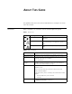
ABOUT THIS GUIDE This guide describes the 3Com® Switch 7700 and how to configure it in version 2.0 of the software. Conventions Table 1 and Table 2 list conventions that are used throughout this guide. Table 1 Notice Icons Icon Notice Type Description Information note Information that describes important features or instructions. Caution Information that alerts you to potential loss of data or potential damage to an application, system, or device.
2 ABOUT THIS GUIDE
1 Product Overview SYSTEM ACCESS ■ Product Overview ■ Configuring the Switch 7700 ■ Setting Terminal Parameters ■ Command Line Interface The 3Com Switch 7700 is a large capacity, modularized wire speed Layer 2/Layer 3 Ethernet switch. It is designed for IP metropolitan area networks (MAN), large-sized enterprise network and campus network users. The Switch 7700 has an integrated chassis structure. The chassis contains a card area, fan area, power supply area, and a power distribution area.
4 CHAPTER 1: SYSTEM ACCESS Table 1 Function Features Features Support IP routing Static route Routing Information Protocol (RIP) V1/v2 Open Shortest Path First (OSPF) DHCP Relay Dynamic Host Configuration Protocol (DHCP) Relay Link aggregation Link aggregation Security features Multi-level user management and password protect 802.
Setting Terminal Parameters 5 Figure 1 Setting up the Local Configuration Environment Through the Console Port RS-232 Serial port Console port Console cable Setting Terminal Parameters To set terminal parameters: 1 Start the PC and select Start > Programs > Accessories > Communications > HyperTerminal. 2 The HyperTerminal window displays the Connection Description dialog box, as shown in Figure 2.
6 CHAPTER 1: SYSTEM ACCESS Figure 3 Properties Dialog Box 5 Click OK. The Port Settings tab, shown in Figure 4, displays and you can set serial port parameters.
Setting Terminal Parameters Figure 4 Set Communication Parameters 6 Click OK. The HyperTerminal dialogue box displays, as shown in Figure 5. 7 Select Properties. Figure 5 HyperTerminal Window 8 In the Properties dialog box, select the Settings tab, as shown in Figure 6. 9 Select VT100 in the Emulation dropdown menu. 10 Click OK.
8 CHAPTER 1: SYSTEM ACCESS Figure 6 Settings Tab Configuring Through Telnet After you have correctly configured the IP address of a VLAN interface for an Ethernet switch through the console port (using the ip address command in VLAN interface view), and added the port (that connects to a terminal) to this VLAN (using the port command in VLAN view), you can telnet this Switch 7700 and configure it.
Setting Terminal Parameters 9 Figure 7 Setting up the Configuration Environment Through Telnet Workstation Ethernet port Server Workstation PC (for configuring the switch through Telnet) 4 Run Telnet on the PC by selecting Start > Run from the Windows desktop and entering Telnet in the Open field, as shown in Figure 8. Click OK. Figure 8 Run Telnet 5 On the Connect dialog box, enter the IP address of the VLAN connected to the PC port and set the terminal type to VT100, as shown in Figure 9.
10 CHAPTER 1: SYSTEM ACCESS Note: When configuring the Ethernet switch by Telnet, do not modify the IP address of it unless necessary, for the modification might terminate the Telnet connection. By default, after logging on, a Telnet user can access the commands at Level 0.
Setting Terminal Parameters Configuring Through a Dial-up the Modem 11 To configure your router through a dial-up modem: 1 Authenticate the modem user through the console port of the Switch 7700 before the user logs in to the switch through a dial-up modem. Note: By default, the password is required for authenticating the modem user to log in to the Switch 7700. If a user logs in through the modem without a password, the user sees the message, Password required, but none set.
12 CHAPTER 1: SYSTEM ACCESS Figure 12 Set the Dialed Number Figure 13 Dial the Remote PC 4 Enter the preset login password on the remote terminal emulator and wait for the prompt. 5 Use the appropriate commands to configure the Switch 7700 or view its running state. Enter ? to get the immediate help. For details on a specific command, refer to the appropriate chapter in this guide. Note: By default, after login, a modem user can access the commands at Level 0.
Setting Terminal Parameters ■ 13 Remote configuration through a modem through the console port. There are two types of user interfaces: ■ AUX user interface is used to log in the Ethernet switch through a dial-up modem. A Switch 7700 can only have one AUX port. ■ VTY user interface is used to telnet the Ethernet switch. Note: For the Switch 7700, the AUX port and Console port are the same port. There is only the type of AUX user interface.
14 CHAPTER 1: SYSTEM ACCESS Perform the following configurations in user interface (AUX user interface only) view. Table 3 Configure the Attributes of the AUX (Console) Port Operation Command Configure the transmission speed on AUX (Console) port. By default, the transmission speed is 9600bps speed speed-value Restore the default transmission speed on AUX (Console) port undo speed Configure the flow control on AUX (Console) port.
Setting Terminal Parameters 15 through the user interface only when the terminal service is enabled again. Use the commands described in Table 4 to enable or disable terminal service. Table 4 Enable/Disable Terminal Service Operation Command Enable terminal service shell Disable terminal service undo shell By default, terminal service is enabled on all the user interfaces.
16 CHAPTER 1: SYSTEM ACCESS Set the History Command Buffer SIze Table 8 describes the history-command max-size command. By default, the size of the history command buffer is 10.
Setting Terminal Parameters 17 2 Configure the local or remote authentication username and password. Use the authentication-mode scheme command to perform local or remote authentication of username and password. The type of the authentication depends on your configuration.
18 CHAPTER 1: SYSTEM ACCESS By default, a user can access the commands at Level 3 after logging in through the AUX user interface, and the commands at Level 0 after logging in through the VTY user interface. When a user logs in to the switch, the command level that the user can access depends on two points. One is the command level that the user itself can access, the other is the set command level of this user interface. If the two levels are different, the former is taken.
Setting Terminal Parameters 19 Configure Redirection The send command can be used for sending messages between user interfaces. See Table 15. Perform the following configuration in user view. Table 15 Configure to Send Messages Between User Interfaces Operation Command Configure to send messages between different user interfaces. send { all | number | type number } The auto-execute command is used to run a command automatically after you log in.
20 CHAPTER 1: SYSTEM ACCESS Table 17 Display and Debug User Interface Command Line Interface Command Line View Operation Command Display the user application information of the user interface display users [ all ] Display the physical attributes and some configurations of the user interface display user-interface [ type number ] [ number ] The Switch 7700 provides a series of configuration commands and command line interfaces for configuring and managing the Switch 7700.
Command Line Interface 21 this level involve file system commands, FTP commands, TFTP commands, XModem downloading commands, user management commands, and level setting commands. Login users are also classified into four levels that correspond to the four command levels. After users of different levels log in, they can only use commands at their own, or lower, levels.
22 CHAPTER 1: SYSTEM ACCESS Figure 14 Relation Diagram of the Views Ethernet port view User interface viiew VLAN view VLAN interface view RIP view OSPF view OSPF area view Route policy view User view Basic ACL view System view Advanced ACL view Interface-based ACL view Layer-2 ACL view FTP client view Local-user view PIM view RADIUS server group view The Table 18 describes the function features of different views and the commands to enter or quit.
Command Line Interface 23 Table 18 Function Feature of Command View Command view Function Prompt VLAN interface view Configure IP interface parameters for a VLAN or a VLAN aggregation [SW7700-Vlaninterface1] Local-user view Configure local user parameters [SW7700-useruser1] User interface view Configure user interface parameters [SW7700-ui0] FTP Client view Configure FTP Client parameters [ftp] Command to enter Command to exit Key in interface vlan-interface 1 in System view quit returns
24 CHAPTER 1: SYSTEM ACCESS Table 18 Function Feature of Command View Feature and Functions of the Command Line Command view Function Prompt Layer-2 ACL view Define the rule of layer-2 ACL [SW7700-acllink-200] RADIUS server group view Configure radius parameters ISP domain view Configure ISP domain parameters Command to enter Command to exit Key in acl number 200 in System view quit returns to System view return returns to user view [SW7700-radius- Key in radius 1] scheme 1 in System view
Command Line Interface 25 -v Verbose output. ICMP packets other than ECHO_RESPONSE that are received are listed STRING<1-20> IP address or hostname of a remote system Ip IP Protocol ■ Enter a command with a ?, separated by a space. If this position is for parameters, all the parameters and their brief descriptions will be listed.
26 CHAPTER 1: SYSTEM ACCESS Table 20 Retrieve History Command Operation Key Retrieve the previous history command Up cursor key <> or Retrieves the previous history command, if there is any. Result Retrieve the next history Down cursor key <> or command Retrieves the next history command, if there is any. Note: Cursor keys can be used to retrieve the history commands in Windows 3.X Terminal and Telnet.
PORT CONFIGURATION 2 This chapter covers the following topics: Ethernet Port Overview ■ Ethernet Port Overview ■ Link Aggregation Configuration A brief description of Switch 7700 I/O modules are listed below: ■ 48-port 10/100Base-T auto-sensing fast Ethernet card ■ 8-port 1000Base-X (Gigabit Interface Converter or GBIC) Gigabit Ethernet card ■ 8-port 10/100/1000Base-T Gigabit Ethernet card ■ 24-port 100Base-FX MMF fast Ethernet card The Ethernet ports of the Switch 7700 have the following fe
28 CHAPTER 2: PORT CONFIGURATION ■ Setting Link Type for Ethernet Port ■ Adding the Ethernet Port to a VLAN ■ Setting the Default VLAN ID for Ethernet Port Entering Ethernet Port View Before configuring the Ethernet port, enter Ethernet port view first. Perform the following configuration in system view. Table 1 Enter Ethernet Port View Operation Command Enter Ethernet port view interface {Gigabit | Ethernet} slot/subslot/port Note: In the Switch 7700, the subslot is always 0.
Ethernet Port Overview 29 Perform the following configuration in Ethernet port view. Table 4 Set Duplex Attribute for Ethernet Port Operation Command Set duplex attribute for Ethernet port. duplex {auto | full | half} Restore the default duplex attribute of Ethernet port. undo duplex Note: 100M electrical Ethernet port can operate in full-duplex, half-duplex or auto-negotiation mode. The Gigabit electrical Ethernet port can operate in full duplex, half duplex or auto-negotiation mode.
30 CHAPTER 2: PORT CONFIGURATION Table 6 Set the Type of the Cable Connected to the Ethernet Port Operation Command Restore the default type of the cable connected to the Ethernet port. undo mdi Note: The settings only take effect on 10/100Base-T and 10/100/1000Base-T ports. The Switch 7700 only supports auto (auto-sensing). If you set some other type, you will see the prompt “Not support this operation!”. The cable type is auto (auto-recognized) by default.
Ethernet Port Overview 31 Setting the Maximum MAC Addresses an Ethernet Port can Learn Use the following command to set an amount limit on MAC addresses learned by the Ethernet port. If the number of MAC address learned by this port exceeds the value set by the user, this port will not learn MAC address. Perform the following configuration in Ethernet port view.
32 CHAPTER 2: PORT CONFIGURATION Adding the Ethernet Port to a VLAN The following commands are used for adding an Ethernet port to a specified VLAN. The access port can only be added to one VLAN, while the hybrid and trunk ports can be added to multiple VLANs. Perform the following configuration in Ethernet port view.
Ethernet Port Overview 33 Table 12 Set the Default VLAN ID for the Ethernet Port Operation Command Restore the default VLAN ID of the trunk port to the default value undo port trunk pvid Note: Set the VLAN VPN Feature ■ The Trunk port and isolate-user-vlan cannot be configured simultaneously, while the hybrid port and isolate-user-vlan can be thus configured.
34 CHAPTER 2: PORT CONFIGURATION forward the packets. The loop test will finish automatically after being executed for a while. Table 14 Display and Debug Ethernet Port Operation Command Configure to perform loopback test on the Ethernet port.
Link Aggregation Configuration Ethernet Port Troubleshooting 35 If the default VLAN ID configuration fails, take the following steps: 1 Execute the display interface or display port command to check if the port is a trunk port or a hybrid port. If it is neither of them, configure it as a trunk port or a hybrid port. 2 Then configure the default VLAN ID. Link Aggregation Configuration Link Aggregation means aggregating several ports together to allow outgoing/incoming payload balance among member ports.
36 CHAPTER 2: PORT CONFIGURATION Trunk port allows frames from several VLANs to pass through, the heavy traffic needs balancing among all the ports. Ethernet Switch (Switch A) is connected to the Ethernet Switch (Switch B) upstream by the aggregation of three ports, Ethernet1/0/1 through Ethernet1/0/3. Figure 2 Configure Link Aggregation Switch B Link Aggregation Switch A Switch C The following configurations are for Switch A. Configure Switch B the same way.
3 VLAN Overview VLAN CONFIGURATION ■ VLAN Overview ■ Configuring GARP/GVRP A virtual local area network (VLAN) groups the devices of a LAN logically, but not physically, into segments to implement the virtual workgroups. Using VLAN technology, network managers can logically divide the physical LAN into different broadcast domains. Every VLAN contains a group of workstations with the same demands. The workstations of a VLAN do not have to belong to the same physical LAN segment.
38 CHAPTER 3: VLAN CONFIGURATION The vlan_id parameter specifies the VLAN ID. Note that the default VLAN, namely VLAN 1, cannot be deleted. Add Ethernet Ports to a VLAN You can use the following command to add Ethernet ports to a VLAN. Perform the following configuration in VLAN view.
VLAN Overview 39 Set or Delete VLAN Description Character String You can use the following command to set or delete VLAN description character string. The description character strings, such as workgroup name and department name, are used to distinguish the different VLANs. Perform the following configuration in VLAN view.
40 CHAPTER 3: VLAN CONFIGURATION Perform the following configuration in VLAN interface view. Table 7 Shut Down or Enable a VLAN interface Operation Command Shut down the VLAN interface shutdown Enabling the VLAN interface undo shutdown The operation of shutting down or enabling the VLAN interface has no effect on the status of the Ethernet ports on the local VLAN.
Configuring GARP/GVRP 41 [SW7700-vlan2] port Ethernet 1/0/1 Ethernet 2/0/1 3 Create VLAN 3 and enters its view. [SW7700-vlan2] vlan 3 4 Add Ethernet 1/0/2 and Ethernet 2/0/2 to VLAN3. [SW7700-vlan3] port Ethernet 1/0/2 Ethernet 2/0/2 Configuring GARP/GVRP Generic Attribute Registration Protocol (GARP), offers a mechanism that is used by the members in the same switching network to distribute, propagate, and register information such as VLAN and multicast addresses.
42 CHAPTER 3: VLAN CONFIGURATION Setting the GARP Timer GARP timers include the hold, join, leave, and leaveall timers. The GARP participant sends join message regularly when join timer times out so that other GARP participants can register its attribute values. When the GARP participant wants to remove some attribute values, it sends a leave message outward. The GARP participant receiving the information starts the leave timer.
Configuring GARP/GVRP 43 Table 10 Display and Debug GARP Configuring GVRP Operation Command Display GARP timer display garp timer [ interface interface-list ] Reset GARP statistics information reset garp statistics [ interface interface-list ] Enable GARP event debugging debugging garp event Disable GARP event debugging undo debugging garp event GARP VLAN Registration Protocol (GVRP) is a GARP application.
44 CHAPTER 3: VLAN CONFIGURATION Perform the following configurations in Ethernet port view. Table 12 Enable/Disable Port GVRP Operation Command Enable port GVRP gvrp Disable port GVRP undo gvrp GVRP should be enabled globally before it is enabled on the port. GVRP can only be enabled or disabled on a Trunk port. By default, global GVRP is disabled. Set GVRP Registration Type The GVRP registration types include normal, fixed and forbidden (see IEEE 802.1Q).
Configuring GARP/GVRP 45 Table 14 Display and Debug GVRP Example: GVRP Configuration Example Operation Command Disable GVRP packet or event debugging undo debugging gvrp { packet | event} The network requirement is to dynamically register and update VLAN information among switches. Figure 2 GVRP Configuration Example E1/01 E2/0/1 Switch B Switch A Configure Switch A: 1 Set Ethernet1/0/1 as a Trunk port and allows all the VLANs to pass through.
46 CHAPTER 3: VLAN CONFIGURATION
4 NETWORK PROTOCOL OPERATION This chapter covers the following topics: Configure IP Address ■ Configure IP Address ■ ARP Configuration ■ DHCP Relay ■ IP Performance IP address is a 32-bit address represented by four octets. IP addresses are divided into five classes: A, B, C, D and E. The octets are set according to the first a few bits of the first octet.
48 CHAPTER 4: NETWORK PROTOCOL OPERATION With the rapid development of the Internet, IP addresses are depleting very fast. The traditional IP address allocation method uses up IP addresses with little efficiency. The concept of mask and subnet was proposed to make full use of the available IP addresses. A mask is a 32-bit number corresponding to an IP address. The number consists of 1s and 0s. Principally, these 1s and 0s can be combined randomly.
Configure IP Address 49 Generally, it is sufficient to configure one IP address for an interface. However, you can also configure more than one IP addresses for an interface, so that it can be connected to several subnets. Among these IP addresses, one is the primary IP address and all others are secondary. By default, the IP address of a VLAN interface is null.
50 CHAPTER 4: NETWORK PROTOCOL OPERATION but not receive the ARP packets, there are probably errors on the Ethernet physical layer. ARP Configuration An IP address cannot be directly used for communication between network devices because devices can only identify MAC addresses. An IP address is only the address of a host in the network layer. To send data packets through the network layer to the destination host, the physical address of the host is required.
DHCP Relay 51 Manually Add/Delete Static ARP Mapping Entries Perform the following configuration in System view. Table 4 Manually Add/Delete Static ARP Mapping Entries Operation Command Manually add a static ARP mapping arp static ip-address mac-address VLANID { entry interface_type interface_num | interface_name } Manually delete a static ARP mapping entry undo arp static ip-address Note: Static ARP mapping entries will not time out, however dynamic ARP mapping entries time out after 20 minutes.
52 CHAPTER 4: NETWORK PROTOCOL OPERATION The DHCP relay serves as conduit between the DHCP Client and the server located on different subnets. The DHCP packets can be relayed to the destination DHCP server (or Client) across network segments. The DHCP clients on different networks can use the same DHCP server. This is economical and convenient for centralized management.
DHCP Relay 53 Note: The backup server IP address cannot be configured independently, instead, it has to be configured together with the master server IP address. The corresponding IP address of the DHCP Server is not configured by default. The DHCP Server address must be configured before DHCP relay can be used. Configure Corresponding DHCP Server Group of the VLAN Interface Perform the following configuration in VLAN interface view.
54 CHAPTER 4: NETWORK PROTOCOL OPERATION configuration. Execute debugging command in user view to debug DHCP Relay configuration. Table 11 Displaying and Debugging DHCP Relay Example: Configuring DHCP Relay Operation Command Display the information about the DHCP server group display dhcp-server groupNo Display the information about the DHCP server group corresponding to the VLAN interface.
DHCP Relay 55 [3Com] vlan 3 [3Com-vlan3] port Ethernet 1/0/3 [3Com] interface vlan 3 [3Com-VLAN-Interface3] ip address 21.2.2.1 255.255.0.0 7 It is necessary to configure a VLAN for the server. However, in order to implement the DHCP relay, the following example configures the servers with the same client end in different VLANs. The corresponding interface VLAN of the DHCP Server Group 1 is configured as 4000, and that of the group 2 is configured as 3001.
56 CHAPTER 4: NETWORK PROTOCOL OPERATION IP Performance TCP attributes to be configured include: ■ synwait timer: When sending the syn packets, TCP starts the synwait timer. If response packets are not received before synwait timeout, the TCP connection will be terminated. The timeout of synwait timer ranges 2 to 600 seconds and it is 75 seconds by default. ■ finwait timer: When the TCP connection state turns from FIN_WAIT_1 to FIN_WAIT_2, finwait timer will be started.
IP Performance Troubleshooting IP Performance 57 If the IP layer protocol works normally but TCP and UDP do work normally, you can enable the corresponding debugging information output to view the debugging information. ■ Use the terminal debugging command to output the debugging information to the console. ■ Use the debugging udp command to enable the UDP debugging to trace the UDP packet. When the router sends or receives UDP packets, the content format of the packet can be displayed in real time.
58 CHAPTER 4: NETWORK PROTOCOL OPERATION
5 ROUTING PROTOCOL OPERATION This chapter covers the following topics: IP Routing Protocol Overview ■ IP Routing Protocol Overview ■ Static Routes ■ RIP ■ OSPF ■ IS-IS ■ BGP ■ IP Routing Policy ■ Route Capacity Routers select an appropriate path through a network for an IP packet according to the destination address of the packet. Each router on the path receives the packet and forwards it to the next router. The last router in the path submits the packet to the destination host.
60 CHAPTER 5: ROUTING PROTOCOL OPERATION Figure 1 About Hops A R R Route Segment R R R C B Networks can have different sizes so the segment lengths connected between two different pairs of routers are also different. If a router in a network is regarded as a node and a route segment in the Internet is regarded as a link, message routing in the Internet works in a similar way as the message routing in a conventional network.
IP Routing Protocol Overview ■ 61 The priority added to the IP routing table for a route — Indicates the type of route that is selected. There may be multiple routes with different next hops to the same destination. These routes can be discovered by different routing protocols, or they can be the static routes that are configured manually. The route with the highest priority (the smallest numerical value) is selected as the current optimal route.
62 CHAPTER 5: ROUTING PROTOCOL OPERATION Routing protocols (as well as the static configuration) can generate different routes to the same destination, but not all these routes are optimal. In fact, at a certain moment, only one routing protocol can determine a current route to a single destination.
Static Routes 63 The following routes are static routes: ■ Reachable route — The normal route in which the IP packet is sent to the next hop by the route marked by the destination. It is a common type of static route. ■ Unreachable route — When a static route to a destination has the reject attribute, all the IP packets to this destination are discarded, and the originating host is informed that the destination is unreachable.
64 CHAPTER 5: ROUTING PROTOCOL OPERATION The IP address and mask use a decimal format. Because the 1s in the 32-bit mask must be consecutive, the dotted decimal mask can also be replaced by the mask-length which refers to the digits of the consecutive 1s in the mask.
Static Routes 65 Perform the following configurations in system view.
66 CHAPTER 5: ROUTING PROTOCOL OPERATION Figure 3 Static Route Configuration C Host 1.1.5.1 1.1.5.2/24 1.1.3.1/24 Switch C 1.1.2.1/24 1.1.3.2/24 1.1.1.2/24 Switch A A 1.1.4.1/24 Switch B Host 1.1.1.1 B Host 1.1.4.2 1 Configure the static route for Ethernet Switch A: [Switch A] ip route-static 1.1.3.0 255.255.255.0 1.1.2.2 [Switch A] ip route-static 1.1.4.0 255.255.255.0 1.1.2.2 [Switch A] ip route-static 1.1.5.0 255.255.255.0 1.1.2.
RIP RIP 67 Routing Information Protocol (RIP) is a simple, dynamic routing protocol, that is Distance-Vector (D-V) algorithm-based. It uses hop counts to measure the distance to the destination host, which is called routing cost. In RIP, the hop count from a router to its directly connected network is 0. The hop count to a network which can be reached through another router is 1, and so on. To restrict the time to converge, RIP prescribes that the cost value is an integer that ranges from 0 to 15.
68 CHAPTER 5: ROUTING PROTOCOL OPERATION validity of the routes. With these mechanisms, RIP, an interior routing protocol, enables the router to learn the routing information of the entire network. RIP has become one of the most popular standards of transmitting router and host routes. It can be used in most campus networks and t regional networks that are simple, yet extensive. For larger and more complicated networks, RIP is not recommended.
RIP 69 Perform the following configurations in RIP view. Table 7 Enable RIP Interface Operation Command Enable RIP on the specified network network network-address interface Disable RIP on the specified network interface undo network network-address Note that after the RIP task is enabled, you should also specify its operating network segment, for RIP only operates on the interface on the specified network.
70 CHAPTER 5: ROUTING PROTOCOL OPERATION RIP-1 from incorrectly receiving and processing the routes with subnet mask in RIP-2. When an interface is running RIP-2, it can also receive RIP-1 packets. Perform the following configuration in VLAN interface view.
RIP 71 Table 11 Specify the Operating State of the Interface Operation Command Disable the interface to send RIP update packet undo rip output The rip work command is functionally equivalent to both rip input and rip output commands. By default, all interfaces except loopback interfaces both receive and transmit RIP update packets.
72 CHAPTER 5: ROUTING PROTOCOL OPERATION Set RIP-2 Packet Authentication RIP-1 does not support packet authentication. However, you can configure packet authentication on RIP-2 interfaces. RIP-2 supports two authentication modes: ■ Simple authentication — Does not ensure security.
RIP 73 Perform the following configurations in RIP view. Table 16 Configure RIP to Import Routes of Other Protocols Operation Command Configure RIP to import routes of other protocols import-route protocol [ cost value ] [route-policy route-policy-name ] Cancel the imported routing information of other protocols undo import-route protocol By default, RIP does not import the route information of other protocols.
74 CHAPTER 5: ROUTING PROTOCOL OPERATION Perform the following configuration in VLAN interface view.
RIP Display and Debug RIP 75 After configuring RIP, execute the display command in all views to display the RIP configuration, and to verify the effect of the configuration. Execute the debugging command in user view to debug the RIP module. Execute the reset command in RIP view to reset the ssytem configuratio parameters of RIP. Table 21 Display and Debug RIP Example: Typical RIP Configuration Operation Command Display the current RIP running state and configuration information.
76 CHAPTER 5: ROUTING PROTOCOL OPERATION [Switch B-rip] network 110.11.2.0 3 Configure RIP on Switch C: [Switch C] rip [Switch C-rip] network 117.102.0.0 [Switch C-rip] network 110.11.2.0 RIP Fault Diagnosis and Troubleshooting 1 The Switch 7700 cannot receive update packets when the physical connection to the peer routing device is normal.
OSPF 77 ■ LSA describes the network topology around a router, so the LSDB describes the network topology of the entire network. Routers can easily transform the LSDB to a weighted directed graph, which actually reflects the topology of the whole network. Obviously, all the routers have a graph that is exactly the same. ■ A router uses the SPF algorithm to calculate the shortest path tree with itself as the root, which shows the routes to the nodes in the autonomous system.
78 CHAPTER 5: ROUTING PROTOCOL OPERATION In a broadcast network, in which all routers are directly connected, any two routers must establish adjacency to broadcast their local status information to the whole AS. In this situation, every change that a router makes results in multiple transmissions, which is not only unnecessary but also wastes bandwidth. To solve this problem, OSPF defines a “designated router” (DR).
OSPF 79 should be noted that after OSPF is disabled, the OSPF-related interface parameters also become invalid.
80 CHAPTER 5: ROUTING PROTOCOL OPERATION By default, OSPF is not enabled. Enter OSPF Area View Perform the following configurations in OSPF view. Table 23 Enter OSPF Area View Operation Command Enter an OSPF area view area area-id Delete a designated OSPF area undo area area-id Specify Interface OSPF divides the AS into different areas. You must configure each OSPF interface to belong to a particular area, identified by an area ID.
OSPF 81 Configure the Network Type on the OSPF Interface The route calculation of OSPF is based on the topology of the adjacent network of the local router. Each router describes the topology of its adjacent network and transmits it to all the other routers. OSPF divides networks into four types by link layer protocol: ■ Broadcast: If Ethernet or FDDI is adopted, OSFP defaults the network type to broadcast. ■ Non-Broadcast Muli-access (NBMA): If Frame Relay, ATM, HDLC or X.
82 CHAPTER 5: ROUTING PROTOCOL OPERATION Perform the following configuration in VLAN interface view. Table 26 Configure a Network Type on the Interface that Starts OSPF Operation Command Configure network type on the interface ospf network-type { broadcast | NBMA | P2MP | P2P } After the interface has been configured with a new network type, the original network type of the interface is removed automatically.
OSPF 83 Note that: ■ The DR on the network is not necessarily the router with the highest priority. Likewise, the BDR is not necessarily the router with the second highest priority. If a new router is added after DR and BDR election, it is impossible for the router to become the DR even if it has the highest priority. ■ The DR is based on the router interface in a certain segment. Maybe a router is a DR on one interface, but it can be a BDR or DROther on another interface.
84 CHAPTER 5: ROUTING PROTOCOL OPERATION Perform the following configuration in VLAN interface view.
OSPF 85 By default, LSU packets are transmitted by seconds. Set an Interval for LSA Retransmission Between Neighboring Routers If a router transmits an LSA to the peer, it requires the acknowledgement packet from the peer. If it does not receive the acknowledgement packet within the retransmission, it retransmits this LSA to the neighbor. You can configure the value of the retransmission interval. Perform the following configuration in VLAN interface view.
86 CHAPTER 5: ROUTING PROTOCOL OPERATION To insure that routes to the destinations outside the AS are still reachable, the ABR in this area generates a default route (0.0.0.0) and advertises it to the non-ABR routers in the area. Note the following items when you configure a STUB area: ■ The backbone area cannot be configured as a STUB area and the virtual link cannot pass through the STUB area.
OSPF 87 Figure 5 NSSA RIP NSSA ABR Area 2 NSSA ASBR Area 1 NSSA Area 0 RIP Perform the following configuration in OSPF Area view.
88 CHAPTER 5: ROUTING PROTOCOL OPERATION transmitted separately. Therefore, the sizes of the LSDBs in other areas can be reduced. Once the aggregate segment of a certain network is added to the area, all the internal routes of the IP addresses in the range of the aggregate segment are no longer separately broadcast to other areas. Only the route summary of the whole aggregate network is advertised.
OSPF 89 type-3 LSAs generated by the ABRs, for which the synchronization mode of the routers in the area is not changed. Perform the following configuration in OSPF area view.
90 CHAPTER 5: ROUTING PROTOCOL OPERATION Perform the following configuration in OSPF Area view. Table 40 Configure the OSPF Area to Support Packet Authentication Operation Command Configure the area to support authentication type authentication-mode [ simple | md5 ] Cancel the configured authentication key undo authentication-mode By default, the area does not support packet authentication.
OSPF 91 is the same as the cost of routes within the AS. Also, this route cost and the route cost of the OSPF itself are comparable. That is, the cost to reach the external route type 1 equals the cost to reach the corresponding ASBR from the local router plus the cost to reach the destination address of the route from the ASBR The external type-2 routes refers to imported EGP routes.
92 CHAPTER 5: ROUTING PROTOCOL OPERATION Table 43 Configure Parameters for OSPF to Import External Routes Operation Command Configure the default tag for the OSPF to import external routes default tag tag Restore the default tag for the OSPF to import external routes undo default tag Configure the default type of external routes that OSPF will import default type { 1 | 2 } Restore the default type of the external routes imported by OSPF undo default type By default, no default cost and tag are a
OSPF 93 Configure OSPF Route Filtering Perform the following configuration in OSPF view.
94 CHAPTER 5: ROUTING PROTOCOL OPERATION Perform the following configuration in OSPF view. Table 48 Disable the Interface to Send OSPF Packets Operation Command Disable the interface to send OSPF packets silent-interface silent-interface-type silent-interface-number Enable the interface to send OSPF packets undo silent-interface silent-interface-type silent-interface-number By default, all the interfaces are allowed to transmit and receive OSPF packets.
OSPF 95 Table 50 Display and Debug OSPF Example: OSPF Configuration Operation Command Display OSPF retransmission list display ospf retrans-queue Display the information of OSPF ABR and ASBR display ospf abr-asbr Display OSPF interface information display ospf interface Display OSPF errors display ospf error Configuring DR Election Based on OSPF Priority In this example, four Switch 7700 routers, Switch A, Switch B, Switch C, and Switch D, which can perform the router functions and run OSPF, a
96 CHAPTER 5: ROUTING PROTOCOL OPERATION 3 Configure Switch C: [Switch [Switch [Switch [Switch [Switch [Switch [Switch C] interface Vlan-interface 1 C-Vlan-interface1] ip address 196.1.1.3 255.255.255.0 C-Vlan-interface1] ospf dr-priority 2 C] router id 3.3.3.3 C] ospf C-ospf] area 0 C-ospf-area-0.0.0.0] network 196.1.1.0 0.0.0.255 4 Configure Switch D: [Switch [Switch [Switch [Switch [Switch [Switch D] interface Vlan-interface 1 D-Vlan-interface1] ip address 196.1.1.4 255.255.255.0 D] router id 4.4.4.
OSPF Figure 7 OSPF Virtual Link Configuration Switch A 1.1.1.1 196.1.1.1/24 Area 0 196.1.1.2/24 197.1.1.2/24 Switch B 2.2.2.2 Area 1 Virtual Link 197.1.1.1/24 Switch C 3.3.3.3 152.1.1.1/24 Area 2 The commands listed below implement this configuration. 1 Configure Switch A: [Switch [Switch [Switch [Switch [Switch [Switch A] interface Vlan-interface 1 A-Vlan-interface1] ip address 196.1.1.1 255.255.255.0 A] router id 1.1.1.1 A] ospf A-ospf] area 0 A-ospf-area-0.0.0.0] network 196.1.1.0 0.0.0.
98 CHAPTER 5: ROUTING PROTOCOL OPERATION OSPF Fault Diagnosis and Troubleshooting 1 OSPF has been configured according to the previous procedures, but OSPF on the router does not run normally. ■ Troubleshoot locally Check whether the protocol between two directly connected routers is operating normally. The normal sign is the peer state machine between the two routers reaches the FULL state.
IS-IS 99 areas. RTB belongs to area0, which complies with the backbone area membership requirement. However, RTC does not belong to area0. Therefore, a virtual link must be set up between RTC and RTB to insure that area2 and area0 (the backbone area) are connected. Figure 8 OSPF Areas RTA ■ ■ IS-IS area0 RTB area1 RTC area2 RTD The backbone area (area0) cannot be configured as the STUB area and the virtual link cannot pass through the STUB area.
100 CHAPTER 5: ROUTING PROTOCOL OPERATION Two-level Structure of IS-IS Routing Protocol IS-IS adopts the two-level structure including Level-1 and Level-2 in a routing domain (or the AS) to support the routing network at a large scale. A large RD is divided into one or more areas. The Level-1 router manages the intra-area routing and is responsible for communicating with other Level-1 routers in the same area. The Level-2 router manages the inter-area routing.
IS-IS 101 Figure 9 IS-IS topology NSAP Structure of IS-IS Routing Protocol Figure 10 illustrates the NSAP structure. The whole address is of 8 to 20 bytes long. Figure 10 NSAP structure NSAP includes initial domain part (IDP) and domain specific part (DSP). IDP and DSP are length-variable with total length of 20 bytes.
102 CHAPTER 5: ROUTING PROTOCOL OPERATION and format identifier (AFI) and initial domain identifier (IDI). AFI defines the format of IDI. DSP has several bytes. Area Address is composed of routing field and area identifier. The routing field includes AFI and IDI and may also includes the first byte of DSP. It identifies the organization structure. It is followed by an area identifier of 16 bits. The following 48 bits (or 6 bytes) of System ID identifies the host or router uniquely.
IS-IS 103 IS-IS configuration includes: ■ Enabling IS-IS and Entering the IS-IS View ■ Setting the Network Entity Title (NET) ■ Enabling IS-IS on the Specified Interface ■ Setting IS-IS Link State Routing Cost ■ Setting the Hello Packet Broadcast Interval ■ Setting the CSNP Packet Broadcast Interval ■ Setting the LSP Packet Interval ■ Setting the LSP Packet Retransmission Interval ■ Setting the Hello Failure Interval ■ Set Priority for DIS Election ■ Setting Interface Circuit Level ■
104 CHAPTER 5: ROUTING PROTOCOL OPERATION Perform the following configurations in system view. Table 51 Enable IS-IS and Enter the IS-IS View Operation Command Enable the IS-IS and enter the IS-IS view isis [ tag ] Cancel the specified IS-IS routing process undo isis [ tag ] The tag parameter identifies the IS-IS process. In present version, just one IS-IS process is allowed. By default, the IS-IS routing process is disabled.
IS-IS 105 Table 54 Set IS-IS Link State Routing Cost Operation Command Restore the default routing cost of the interface undo isis cost [ level-1 | level-2 ] If the level is not specified, the default setting is Level-1 routing cost. The value parameter is configured according to the link state of the Interface. By default, the routing cost of IS-IS on Interface is 10.
106 CHAPTER 5: ROUTING PROTOCOL OPERATION If the level is not specified, it defaults to setting CSNP packet broadcast interval for Level-1. By default, the CSNP packet is transmitted by interface every 10 second. Setting the LSP Packet Interval LSP carries the link state records for propagation throughout the area. Perform the following configurations in VLAN interface view.. Table 57 Set the LSP Packet Interval Operation Command Set LSP packet interval on the interface, measured in milliseconds.
IS-IS 107 Set Priority for DIS Election In the broadcast network, the IS-IS needs to elect a DIS from all the routers. When you need to select a DIS from the IS-IS neighbors on the broadcast network, you should select level-1 DIS and level-2 DIS. The higher the priority is, the more possible it is selected. If there are two or more routers with the highest priority in the broadcast network, the one with the greatest MAC address will be selected.
108 CHAPTER 5: ROUTING PROTOCOL OPERATION Perform the following configurations in VLAN interface view..
IS-IS 109 Setting Default Route Generation In the IS-IS route domain, the Level-1 router only has the LSDB of the local area, so it can only generate the routes in the local areas. But the Level-2 router has the backbone LSDB in the IS-IS route domains and generates the backbone network routes only. If a Level-1 router in one area wants to forward the packets to other areas, it needs to first forward the packets to the closest Level-1-2 router in the local area along its default route.
110 CHAPTER 5: ROUTING PROTOCOL OPERATION Setting a Summary Route You can aggregate several different routes, which turns advertisement processes of several routes to the advertisement of single route so as to simplify the routing table. Perform the following configurations in IS-IS view..
IS-IS 111 Setting Peer Change Logging After peer changes log is enabled, the IS-IS peer changes will be output on the configuration terminal until the log is disabled. Perform the following configurations in IS-IS view.. Table 70 Set to Log the Peer Changes Operation Command Enable peer changes log log-peer-change Disable peer changes log undo log-peer-change By default, the peer changes log is disabled.
112 CHAPTER 5: ROUTING PROTOCOL OPERATION Perform the following configurations in IS-IS view.. Table 73 Set SPF Calculation in Slice Operation Command Set SPF calculation in slice spf-slice-size seconds Restore the default configuration undo spf-slice-size By default, SPF calculation does not divide into slices but runs to the end once, which can also be implemented by setting the parameter seconds to 0.
IS-IS 113 By default, SPF calculation runs every 5 seconds. Enabling or Disabling the Interface to Send Packets To prevent the IS-IS routing information from obtaining by some router in a certain network, the silent-interface command can be used to prohibit sending IS-IS packets by the interface connecting with the router. Perform the following configurations in IS-IS view..
114 CHAPTER 5: ROUTING PROTOCOL OPERATION Configuring IS-IS Route Filtering The IS-IS protocol can filter the received and distributed routes according to the access control list specified by acl-number. Perform the following configurations in IS-IS view. ■ Configure filtering of the routes received by IS-IS .
IS-IS 115 Resetting All the IS-IS Data Structure When it is necessary to refresh some LSPs immediately, perform the following configuration in user view.. Table 81 Resetting all the IS-IS Data Structures Operation Command Reset the IS-IS data structure reset isis all Resetting the Specified IS-IS Peer When it is necessary to connect a specified peer again, perform the following configuration in user view..
116 CHAPTER 5: ROUTING PROTOCOL OPERATION Figure 11 IS-IS Configuration Example 1 Configure Switch A [Switch A] isis [Switch A-isis] network-entity 86.0001.0000.0000.0005.00 [Switch A] interface vlan-interface 100 [Switch A-Vlan-interface100] isis enable [Switch A] interface vlan-interface 101 [Switch A-Vlan-interface101] isis enable [Switch A] interface vlan-interface 102 [Switch A-Vlan-interface102] isis enable 2 Configure Switch B [Switch B] isis [Switch B-isis] network-entity 86.0001.0000.0000.0006.
BGP 117 [Switch C-Vlan-interface101] isis enable [Switch C] interface vlan-interface 100 [Switch C-Vlan-interface100] isis enable 4 Configure Switch D [Switch D] isis [Switch D-isis] network-entity 86.0001.0000.0000.0008.00 [Switch D] interface vlan-interface 102 [Switch D-Vlan-interface102] isis enable [Switch D] interface vlan-interface 100 [Switch D-Vlan-interface100] isis enable BGP Border Gateway Protocol (BGP) is an inter-AS dynamic route discovery protocol.
118 CHAPTER 5: ROUTING PROTOCOL OPERATION abundant route policies to implement flexible filtering and selecting of routes, which can be extended easily to support new developments of the network. BGP, as an upper-layer protocol, runs on a special router. On the first startup of the BGP system, the BGP router exchanges routing information with its peers by transmitting the complete BGP routing table, after that only update messages are exchanged.
BGP ■ Configuring BGP Route Summarization ■ Configuring an BGP Route Reflector ■ Configuring BGP AS Confederation Attributes ■ Configuring BGP Route Dampening ■ Configuring the Repeating Time for a Local AS ■ Configuring the Redistribution of BGP and IGP ■ Defining ACL, AS Path List, and Route Policy ■ Configuring BGP Route Filtering ■ Clearing the BGP Connection 119 Enabling BGP To enable BGP, local AS number should be specified.
120 CHAPTER 5: ROUTING PROTOCOL OPERATION Perform the following configurations in BGP view. Configuring an AS number To configure a BGP peer group as the neighbor of local router, the AS to which the peer group belongs should be specified first. Exchange of routing information between two ends is disabled until the peer ends and AS to which the peer ends belong are specified.
BGP 121 Table 88 Configure a Description of a Peer Group Operation Command Delete description of a peer group undo peer { peer-address | group-name } description By default, no BGP peer group description is set. Configuring to Permit Connections with EBGP Peer Groups on Indirectly Connected Networks Generally, EBGP peers must be connected physically. Otherwise the command below can be used to perform the configuration to make them communicate with each other normally.
122 CHAPTER 5: ROUTING PROTOCOL OPERATION By default, the intervals at which route update messages are sent by an IBGP and EBGP peer group are 5 seconds and 30 seconds respectively.
BGP 123 Configuring a Route Map for a Peer Group By configuring the route map for a peer group, the routes coming from the peer group or advertised to the peer group can be controlled. The route map of advertised routes configured for each member of a peer group must be same with that of the peer group but their route maps of coming routes may be different.
124 CHAPTER 5: ROUTING PROTOCOL OPERATION Removing Private AS Numbers While Transmitting BGP Update Messages Generally, the AS numbers (public AS numbers or private AS numbers) are included in the AS paths while transmitting BGP update messages. This command is used to configure certain outbound routers to ignore the private AS numbers while transmitting update messages.
BGP 125 Perform the following configurations in BGP view. Table 103 Configuring a BGP Timer Operation Command Configure BGP Timer peer { group-name | peer-address } timer keep-alive keepalive-interval hold holdtime-interval Restore the default value of the timer undo peer { group-name | peer-address } timer By default, the interval of sending keepalive packet is 60 seconds. The interval of sending holdtime packet is 180 seconds.
126 CHAPTER 5: ROUTING PROTOCOL OPERATION By default, the MED metric is 0. Comparing the MED Routing Metrics from the Peers in Different ASs This comparison is used to select the best route. The route with smaller MED value will be selected. Perform the following configurations in BGP view.
BGP 127 Configuring BGP Route Summarization The CIDR supports route summarization. There are two modes of BGP route summarization: summary automatic and aggregate. The summary automatic is the summary of the BGP subnet routes. After the configuration of the summary automatic, the BGP will not be able to receive subnets imported by the IGP; the aggregate is the aggregation of the BGP local routes. A series of parameters can be configured in the aggregate.
128 CHAPTER 5: ROUTING PROTOCOL OPERATION Figure 12 The Route Reflector Diagram The reflector is the router that can complete the route reflection function. The route reflector regards the IBGP peers as client and non-client. All peers that do not belong to such cluster in the autonomous system are the non-clients. The designation of route reflector and the addition of the client peer are implemented with the command peer reflect-client.
BGP 129 Two Kinds of Measures to Avoid Looping Inside AS As route reflector is imported, it is possible that path looping will be generated in AS. Path update packets already left the cluster may attempt to return to the cluster. The conventional AS path method can’t detect the internal AS looping, because the path update packet hasn’t left AS.
130 CHAPTER 5: ROUTING PROTOCOL OPERATION Perform the following configurations in BGP view. Table 112 Configuring the Sub-AS of the Confederation Operation Command Configure a confederation consisting of which confederation peer-as as-number-1 [ ... sub-ASs as-number-n ] Cancel the specified sub-AS in the confederation undo confederation peer-as [ as-number-1 ] [ ...as-number-n ] By default, no autonomous system is configured as a member of the confederation.
BGP 131 Table 114 Configuring BGP Route Dampening Operation Command Cancel BGP route dampening undo dampening By default, route dampening is disabled. Note that the parameters in the command are dependent on one another. If one parameter is configured, other parameters must be specified. Configuring the Repeating Time for a Local AS Using peer allow-as-loop command, the repeating time of local AS can be configured. Perform the following configurations in BGP view.
132 CHAPTER 5: ROUTING PROTOCOL OPERATION Defining the AS Path List The routing information packet of the BGP includes an AS path domain. The AS path-list can be used to match with the AS path domain of the BGP routing information to filter the routing information, which does not conform to the requirements. For the same list number, the user can define multiple pieces of an AS path-list. Each AS path list is identified with digit. Please perform the following configurations in the system view.
BGP 133 Please perform the following configuration in the BGP view.
134 CHAPTER 5: ROUTING PROTOCOL OPERATION Table 121 Display and Debug BGP Operation Command Display route flapping statistics information display bgp routing-table flap-info [ { regular-expression as-regular-expression } | { as-path-acl acl-number } | { network-address [ mask [ longer-match ] ] } ] View routes with different source ASs display bgp routing-table different-origin-as Display neighbors information display bgp peer peer-address verbose display bgp peer [ verbose ] Display the routing i
BGP Figure 13 Networking Diagram of AS Confederation Configuration 1 Configure Switch A: [Switch A] bgp 1001 [Switch A-bgp] confederation id 100 [Switch A-bgp] confederation peer-as 1002 1003 [Switch A-bgp] peer 172.68.10.2 as-number 1002 [Switch A-bgp] peer 172.68.10.3 as-number 1003 2 Configure Switch B: [Switch B] bgp 1002 [Switch B-bgp] confederation id 100 [Switch B-bgp] confederation peer-as 1001 1003 [Switch B-bgp] peer 172.68.10.1 as-number 1001 [Switch B-bgp] peer 172.68.10.
136 CHAPTER 5: ROUTING PROTOCOL OPERATION Configuring BGP Route Reflector Switch B receives an update packet passing EBGP and transmits it to Switch C. Switch C is a reflector with two clients: Switch B and Switch D. When Switch C receives a route update from Switch B, it will transmit such information to Switch D. It is required to establish an IBGP connection between Switch B and Switch D, because Switch C reflects information to Switch D.
BGP 137 3 Configure Switch C: a Configure VLAN 3: [Switch C] interface Vlan-interface 3 [Switch C-Vlan-interface3] ip address 193.1.1.1 255.255.255.0 b Configure VLAN 4: [Switch C] interface vlan-Interface 4 [Switch C-Vlan-interface4] ip address 194.1.1.1 255.255.255.0 [Switch C] ospf [Switch C-ospf] area 0 [Switch C-ospf-area-0.0.0.0] network 194.1.1.0 0.0.0.255 c Configure BGP peers and route reflector: [Switch C] bgp 200 [Switch C-bgp] peer 193.1.1.2 as-number 200 [Switch C-bgp] peer 193.1.1.
138 CHAPTER 5: ROUTING PROTOCOL OPERATION Using the display bgp routing-table command ,you can view the BGP routing table on Switch D. Note: Switch D also knows the existence of network 1.0.0.0. display bgp routing-table Flags: # - valid, ^ - best, D - damped, H - history, I - internal, S aggregate suppressed Dest/Mask Pref Origin As-Path *> 1.0.0.0/8 100 Next-Hop 192.1.1.
BGP ■ 139 Add ACL on Switch A, enable network 1.0.0.0. [Switch A] acl number 1 [Switch A-acl-basic-1] rule permit source 1.0.0.0 0.255.255.255 ■ Define two route policies, one is called apply_med_50 and the other is called apply_med_100. The first MED attribute with the route policy as network 1.0.0.0 is set as 50, while the MED attribute of the second is 100.
140 CHAPTER 5: ROUTING PROTOCOL OPERATION [Switch C] interface Vlan-interface 3 [Switch C-Vlan-interface3] ip address 193.1.1.2 255.255.255.0 [Switch C] interface vlan-interface 5 [Switch C-Vlan-interface5] ip address 195.1.1.2 255.255.255.0 [Switch C] ospf [Switch C-ospf] area 0 [Switch C-ospf-area-0.0.0.0] network 193.1.1.0 0.0.0.255 [Switch C-ospf-area-0.0.0.0] network 195.1.1.0 0.0.0.255 [Switch C] bgp 200 [Switch C-bgp] peer 193.1.1.1 as-number 100 [Switch C-bgp] peer 195.1.1.
BGP 141 [Switch C-acl-basic-1] rule permit source 1.0.0.0 0.255.255.255 ■ Define the route policy with the name of localpref, of those, the local preference matching ACL 1 is set as 200, and that of not matching is set as 100.
142 CHAPTER 5: ROUTING PROTOCOL OPERATION IP Routing Policy When a router distributes or receives routing information, it needs to implement some policies to filter the routing information so it can receive or distribute the routing information that meets only the specified condition. A routing protocol such as RIP may need to import routing information discovered by other protocols to enrich its routing knowledge.
IP Routing Policy 143 IP Prefix The function of the ip-prefix is similar to that of the acl, but it is more flexible and easier for users to understand. When the ip-prefix is applied to routing information filtering, its matching objects are the destination address information, domain of the routing information. In addition, in the ip-prefix, you can specify the gateway options and require it to receive only the routing information distributed by certain routers.
144 CHAPTER 5: ROUTING PROTOCOL OPERATION The permit argument specifies that if a route satisfies all the if-match clauses of a node, the route passes the filtering of the node, and the apply clauses for the node are executed without taking the test of the next node. If a route does not satisfy all the if-match clauses of a node, however, the route takes the test of the next node. The deny argument specifies that the apply clauses are not executed.
IP Routing Policy 145 Table 123 Define If-match Conditions Operation Command Cancel the matched next-hop of the routing information undo if-match ip next-hop [ip-prefix ip-prefix-name ] Match the routing cost of the routing information if-match cost cost Cancel the matched routing undo if-match cost cost of the routing information Match the tag domain of the OSPF routing information if-match tag value Cancel the tag domain of the matched OSPF routing information undo if-match tag By default, no
146 CHAPTER 5: ROUTING PROTOCOL OPERATION Table 124 Define Apply Clauses Operation Command Set the routing cost of the routing information apply cost value Cancel the routing cost of the routing information undo apply cost set the cost type of the routing information apply cost-type [ internal | external ] remove the setting of the cost type undo apply cost-type Set the route origin of the BGP routing information apply origin { igp | egp as-number | incomplete } Cancel the route origin of the BG
IP Routing Policy 147 Define IP Prefix A prefix list is identified by the IP prefix name. Each IP prefix can include multiple items, and each item can independently specify the matching range of the network prefix forms. The index-number specifies the matching sequence in the prefix list. Perform the following configurations in system view.
148 CHAPTER 5: ROUTING PROTOCOL OPERATION Configuring Filtering for the Distributed Routes Define a policy concerning route distribution that filters the routing information that does not satisfy the conditions and distributes routes with the help of an ACL or address ip-prefix. Perform the following configuration in routing protocol view.
IP Routing Policy 149 Figure 16 Filtering Received Routing Information static 20.0.0.1/8 30.0.0.1/8 40.0.0.1/8 1.1.1.1 2.2.2.2 area 0 Switch A Switch B Configure Switch A: 1 Configure the IP address of VLAN interface. [Switch [Switch [Switch [Switch A] interface vlan-interface 100 A-Vlan-interface100] ip address 10.0.0.1 255.0.0.0 A] interface vlan-interface 200 A-Vlan-interface200] ip address 12.0.0.1 255.0.0.0 2 Configure three static routes. [Switch A] ip route-static 20.0.0.1 255.255.255.
150 CHAPTER 5: ROUTING PROTOCOL OPERATION Route Capacity ■ The if-match mode of at least one node of the Route policy should be the permit mode. When a Route-policy is used for the routing information filtering, if a piece of routing information does not pass the filtering of any node, then it means that the route information does not pass the filtering of the Route-policy.
Route Capacity 151 Setting the Lower Limit for Switch Memory When the Ethernet switch memory is equal to or lower than the lower limit, BGP and OSPF will be disconnected. Perform the following configurations in system view.
152 CHAPTER 5: ROUTING PROTOCOL OPERATION Perform the following configuration in the system view.
Route Capacity Displaying and Debugging Route Capacity After the above configuration, executethe display command in all views to display the running of the Route capacity configuration.
154 CHAPTER 5: ROUTING PROTOCOL OPERATION
6 MULTICAST PROTOCOL This chapter includes information on the following: IP Multicast Overview ■ IP Multicast Overview ■ GMRP ■ IGMP Snooping ■ Common Multicast Configuration ■ IGMP Configuration ■ PIM-DM Configuration ■ PIM-SM Configuration Many transmission methods can be used when the destination (including data, voice and video) is the secondary use of the network. You should establish an independent data transmission path for each user if the multicast method is used.
156 CHAPTER 6: MULTICAST PROTOCOL Figure 1 Comparison Between the Unicast and Multicast Transmission Receiver Unicast Receiver Server Receiver Receiver Multicast Receiver Server Receiver Note: A multicast source does not necessarily belong to a multicast group. It only sends data to the multicast group and it is not necessarily a receiver. Multiple sources can send packets to a multicast group simultaneously. A router that does not support multicast may exist on the network.
IP Multicast Overview 157 Ranges and meanings of Class D addresses are shown in Table 1. Table 1 Ranges and Meanings of Class D Addresses Class D address range Meaning 224.0.0.0∼224.0.0.255 Reserved multicast addresses (addresses of permanent groups). Address 224.0.0.0 is reserved. The other addresses can be used by routing protocols. 224.0.1.0∼238.255.255.255 Multicast addresses available for users (addresses of temporary groups). They are valid in the entire network. 239.0.0.0∼239.255.255.
158 CHAPTER 6: MULTICAST PROTOCOL Figure 2 Mapping Between the Multicast IP Address and the Ethernet MAC Address 32-bit IP address 5 bits Lower 23 bits directly mapped not mapped 48-bit MAC address Only 23 bits of the last 28 bits in the IP multicast address are mapped to the MAC address. Therefore the 32 IP multicast addresses are mapped to the same MAC address. IP Multicast Protocols Multicast uses the multicast group management protocol and multicast routing protocol.
IP Multicast Overview 159 resources related (such as bandwidth and CPU of routers) are consumed. In order to decrease the consumption of these precious network resources, branches that do not have members send Prune messages toward the source to reduce the unwanted/unnecessary traffic. To enable the receivers to receive multicast data streams, the pruned branches can be restored periodically to a forwarding state.
160 CHAPTER 6: MULTICAST PROTOCOL Application of Multicast IP multicast technology effectively solves the problem of packet forwarding from single-point to multi-point. It implements high-efficient data transmission from single-point to multi-point in IP networks and can save a large amount of network bandwidth and reduce network loads.
GMRP 161 By default, GMRP is disabled. Enabling/Disabling GMRP on the Port Perform the following configuration in Ethernet port view. Table 4 Enabling/Disabling GMRP on the Port Operation Command Enable GMRP on the port gmrp Disable GMRP on the port undo gmrp GMRP should be enabled globally before being enabled on a port. By default, GMRP is disabled on the port.
162 CHAPTER 6: MULTICAST PROTOCOL [SW7700-Ethernet1/0/1] gmrp IGMP Snooping IGMP Snooping (Internet Group Management Protocol Snooping) is a multicast control mechanism running on layer 2. It is used for multicast group management and control. IGMP Snooping runs on the link layer. When receiving the IGMP messages, the Layer 2 Switch 7700 uses IGMP Snooping to analyze the information. If the switch hears IGMP host report message from an IGMP host, it adds the host to the corresponding multicast table.
IGMP Snooping 163 Figure 5 Multicast Packet Transmission with IGMP Snooping Video stream Internet/Intranet Multicast router Video stream VOD server Layer 2 Ethernet switch Video stream Video stream Multicast group member Nonmulticast group member Video stream Nonmulticast group member Implement IGMP Snooping This section introduces related switch concepts of IGMP Snooping: ■ Router Port: The port directly connected to the multicast router.
164 CHAPTER 6: MULTICAST PROTOCOL Figure 6 Implementing IGMP Snooping Internet A router running IGMP IGMP packets An Ethernet switch running IGMP snooping IGMP packets 1 IGMP general query message: Transmitted by the multicast router to query which multicast group contains member. When a router port receives an IGMP general query message, the Switch 7700 will reset the aging timer of the port.
IGMP Snooping 165 any member, the switch will notify the multicast router to remove it from the multicast tree. Configure IGMP Snooping The main IGMP Snooping configuration includes: ■ Enabling/disabling IGMP Snooping ■ Configuring the aging time of router port ■ Configuring maximum response time ■ Configuring the aging time of multicast group member port Of the above configuration tasks, enabling IGMP Snooping is required, while others are optional.
166 CHAPTER 6: MULTICAST PROTOCOL Perform the following configuration in system view. Table 8 Configuring the Maximum Response Time Operation Command Configure the maximum response time igmp-snooping max-response-time seconds Restore the default setting undo IGMP-snooping max-response-time By default, the maximum response time is 10 seconds. Configure Aging Time of Multicast Group Member This task sets the aging time of the multicast group member port.
Common Multicast Configuration 167 Figure 7 IGMP Snooping Configuration Network Internet Router Multicast Switch 1 Display the status of GMRP. display gmrp status 2 Display the current status of IGMP Snooping when GMRP is disabled. display igmp-snooping configuration 3 Enable IGMP Snooping if it is disabled.
168 CHAPTER 6: MULTICAST PROTOCOL Common Multicast Configuration Common multicast configuration includes: ■ Enabling multicast Enabling Multicast Enable multicast first before enabling the multicast routing protocol. Enabling multicast will automatically enable IGMP operation on all interfaces. Perform the following configuration in system view.
IGMP Configuration IGMP Configuration 169 IGMP (Internet Group Management Protocol) is a protocol in the TCP/IP suite responsible for management of IP multicast members. It is used to establish and maintain multicast membership among IP hosts and their connected neighboring routers. IGMP excludes transmitting and maintenance information among multicast routers, which are completed by multicast routing protocols. All hosts participating in multicast must implement IGMP.
170 CHAPTER 6: MULTICAST PROTOCOL multicast group. This prevents the hosts of members of other multicast groups from sending response messages. ■ Max response time The Max Response Time is added in IGMP Version 2. It is used to dynamically adjust the allowed maximum time for a host to response to the membership query message. IGMP Configuration Once multicast is enabled, IGMP will automatically run on each interface. Generally, IGMP does not need to be configured.
IGMP Configuration 171 Limit ing Access to IP Multicast Groups A multicast router learns whether there are members of a multicast group on the network by the received IGMP membership message. A filter can be set on an interface to limit the range of allowed multicast groups. Perform the following configuration in VLAN-interface view.
172 CHAPTER 6: MULTICAST PROTOCOL Configuring the IGMP Querier Present Timer The IGMP querier present timer defines the period of time before the router takes over as the querier. Perform the following configuration in VLAN interface view.
PIM-DM Configuration 173 Table 19 Display and Debug IGMP PIM-DM Configuration Operation Command Display the IGMP configuration and running information about the interface display igmp interface [ interface-type interface-number ] Enable the IGMP information debugging debugging igmp { all | event | host | packet | timer } Disable the IGMP information debugging undo debugging igmp { all | event | host | packet | timer } PIM-DM (Protocol Independent Multicast, Dense Mode) belongs to dense mode mult
174 CHAPTER 6: MULTICAST PROTOCOL independent of any specified unicast routing protocol such as the routing information learned by RIP and OSPF ■ Assert mechanism As shown in the following figure, both routers A and B on the LAN have their own receiving paths to multicast source S. In this case, when they receive a multicast packet sent from multicast source S, they will both forward the packet to the LAN. Multicast Router C at the downstream node will receive two copies of the same multicast packet.
PIM-DM Configuration 175 Perform the following configuration in VLAN interface view. Table 20 Enable PIM-DM Operation Command Enable PIM-DM on an interface pim dm Disable PIM-DM on an interface undo pim dm It’s recommended you configure PIM-DM on all interfaces in non-special cases. This configuration is effective only after the multicast routing is enabled in system view. Once enabled PIM-DM on an interface, PIM-SM cannot be enabled on the same interface and vice versa.
176 CHAPTER 6: MULTICAST PROTOCOL Table 22 Display and Debug PIM-DM PIM-DM Configuration Example Operation Command Display the information about PIM neighboring routers display pim neighbor [ interface interface-type interface-number ] Enable the PIM debugging debugging pim common { all | event | packet | timer } Disable the PIM debugging undo debugging pim common { all | event | packet | timer } Enable the PIM-DM debugging debugging pim dm { all | mbr | mrt | timer | warning | { recv | send }
PIM-SM Configuration 177 [SW7700-vlan-interface11] ip address 2.2.2.2 255.255.0.0 [SW7700-vlan-interface11] pim dm [SW7700-vlan-interface11] quit [SW7700] interface vlan-interface 12 [SW7700-vlan-interface12] ip address 3.3.3.3 255.255.0.0 [SW7700-vlan-interface12] pim dm PIM-SM Configuration PIM-SM (Protocol Independent Multicast, Sparse Mode) belongs to sparse mode multicast routing protocols. PIM-SM is mainly applicable to large-scale networks with broad scope with few group members.
178 CHAPTER 6: MULTICAST PROTOCOL RP Multicast Source S RPT Receiver join Multicast source registration Figure 10 RPT Schematic Diagram RP Multicast source S RPT Receiver join Multicast source registration Multicast Source Registration When multicast source S sends a multicast packet to the group G, the PIM-SM multicast router is responsible for encapsulating the packet into a registration packet upon receipt. It then sends the packet to the corresponding RP in unicast.
PIM-SM Configuration 179 calculate the RPs corresponding to multicast groups according to the same algorithm after receiving the C-RP messages that the BSR advertises. It should be noted that one RP can serve multiple multicast groups or all multicast groups. Each multicast group can only be uniquely correspondent to one RP at a time rather than multiple RPs. Configure BSRs The BSR is the management core in a PIM-SM network.
180 CHAPTER 6: MULTICAST PROTOCOL Once enabled , PIM-DM cannot be enabled on the same interface. Configure the Interface Hello Message Interval Generally, PIM-SM advertises Hello messages periodically on the interface enabled with it to detect PIM neighbors and discover which router is the Designated Router (DR). Perform the following configuration in VLAN interface view.
PIM-SM Configuration 181 Using undo pim command, you can clear the configuration in PIM view, and back to system view. Configure Candidate-BSRs In a PIM domain, one or more candidate BSRs should be configured. A BSR (Bootstrap Router) is elected among candidate BSRs. The BSR takes charge of collecting and advertising RP information. The automatic election among candidate BSRs is described as follows.
182 CHAPTER 6: MULTICAST PROTOCOL multicast group in the specified range. It is suggested to configure Candidate RP on the backbone router. Configure RP to Filter the Register Messages Sent by DR In the PIM-SM network, the register message filtering mechanism can control which sources to send messages to which groups on the RP, i.e., RP can filter the register messages sent by DR to accept specified messages only. Perform the following configuration in PIM view.
PIM-SM Configuration 183 Table 31 Display and Debug PIM-SM Operation Command Display the RP information display pim rp-info [ group-address ] Enable the PIM-SM debugging debugging pim sm { all | mbr | register-proxy | mrt | timer | warning | { recv | send } { assert | graft | graft-ack | join | prune } } Disable the PIM-SM debugging Example: Configuring PIM-SIM undo debugging pim sm { all | mbr | register-proxy | mrt | timer | warning | { recv | send } { assert | graft | graft-ack | join | prune } }
184 CHAPTER 6: MULTICAST PROTOCOL [SW7700] vlan 12 [SW7700-vlan12] port Ethernet 1/0/6 to Ethernet 1/0/7 [SW7700-vlan12] quit [SW7700] pim [SW7700-pim] interface vlan-interface 12 [SW7700-vlan-interface12] pim sm [SW7700-vlan-interface12] quit 2 Configure the threshold for multicast group to switch from shared tree to the STP as 10kbps. [SW7700] acl number 5 [SW7700-acl-basic-5] rule permit source 225.0.0.1 0.255.255.
PIM-SM Configuration Configure LS_C: 1 Enable PIM-SM.
186 CHAPTER 6: MULTICAST PROTOCOL
7 ACL Overview QOS/ACL OPERATION ■ ACL Overview ■ Configuring ACL ■ Displaying and Debugging ACL ■ QoS Overview ■ User LogonACL Control Configuration A series of matching rules are required for the network devices to identify the packets to be filtered. After identifying the packets, the switch can permit or deny them to pass through according to the defined policy. The Access Control List (ACL) is used to implement these functions.
188 CHAPTER 7: QOS/ACL OPERATION This type of filtering includes: ACL cited by route policy function, ACL used for controlling user logons, and so on. Note: The depth-first principle puts the statement specifying the smallest range of packets on the top of the list. This can be implement, the fewer hosts it can specify. For example, 129.102.1.1 0.0.0.0 specifies a host, while 129.102.1.1 0.0.255.255 specifies a network segment, 129.102.0.1 through 129.102.255.255.
Configuring ACL 189 Table 1 Quantitative Limitation to the ACL Configuring ACL Item Value range Maximum Maximum sub items for all ACL ( for Salience II ) - 1536 ACL configuration includes the tasks described in the following sections: ■ Configuring the Time Range ■ Selecting the ACL Mode ■ Defining ACL ■ Activating ACL These steps must be done in sequence.
190 CHAPTER 7: QOS/ACL OPERATION Perform the following configuration in system view. Table 3 Select ACL Mode Operation Command Select ACL mode acl mode { ip-based | link-based } The Switch 7700 uses ip-based mode and the L3 traffic classification rule by default. Defining ACL The Switch 7700 supports several kinds of ACLs. to define the ACL: 1 Enter the corresponding ACL view 2 Add a rule to the ACL You can add multiple rules to one ACL.
Configuring ACL 191 the packet priority to process the data packets. The advanced ACL supports the analyses of three kinds of packet priorities, ToS (Type of Service), IP, and DSCP priorities. Perform the following configuration in designated view.
192 CHAPTER 7: QOS/ACL OPERATION The numbered interface ACLs can be identified with numbers ranging from 1000 to 1999. Notes: The Switch 7700 does not have any Layer-3 physical interface but has Layer-3 VLAN virtual interface. Therefore when the command line prompts for the input interface type, you can only select Vlan-interface. Otherwise, the system will display a failure message. Interface ACL is only used to filter or classify the data treated by the software of the switch.
Displaying and Debugging ACL Displaying and Debugging ACL 193 After you configure ACL, execute the display command in all views to display the running of the ACL configuration, and to verify the effect of the configuration. Execute the reset command in user view to clear the statistics of the ACL module.
194 CHAPTER 7: QOS/ACL OPERATION Define the work time range: 1 Set the time range from 8:00 to 18:00. [SW7700] time-range 3com 8:00 to 18:00 Define the ACL to access the payment server: 1 Enter the name of the advanced ACL. [SW7700] acl name traffic-of-payserver advanced match-order config 2 Set the rules for other department to access the payment server. [SW7700-acl-adv-traffic-of-payserver] rule 1 deny ip source any destination 129.110.1.2 0.0.0.
QoS Overview 195 such as MAC address, IP protocol, source IP address, destination IP address, and the port number of application can be used for traffic classification. Generally, the classification standards are encapsulated in the header of the packets. The packet content is seldom used as the classification standard. Packet Filter Packet filters filter network traffic.
196 CHAPTER 7: QOS/ACL OPERATION Figure 2 SP high queue Packets sent through this interface Packets sent middle queue normal queue Classify bottom queue Dequeue Sending queue The SP is designed for the key service application. A significant feature of the key service is required for priority to enjoy the service to reduce the responding delay when congestion occurs.
QoS Overview 197 This random number is compared with the discarding probability for the current queue. Any packet whose random number is greater than the probability is discarded. The longer the queue, the higher the discarding probability . However, there is a maximum discarding probability. Through randomly discarding packets, RED avoids global TCP synchronism.
198 CHAPTER 7: QOS/ACL OPERATION Perform the following configuration in Ethernet port view.
QoS Overview 199 Configure the RED Operation The function of the RED Operation is to avoid congestion in advance. Perform the following configuration in Ethernet port view.
200 CHAPTER 7: QOS/ACL OPERATION Displaying and Debugging QoS After you configure QoS, execute the display command in all views to display the running of the QoS configuration, and to verify the effect of the configuration. Execute the reset command in user view to clear the statistics of the QoS module.
User LogonACL Control Configuration 201 Figure 3 Access Control Configuration Example Pay query server 129.110.1.2 E1/0/1 Switch Connected to a router Note: In the following configurations, only the commands related to QoS/ACL configurations are listed. Define the traffic accessing the payment query server: 1 Enter the named advanced ACL view, identified as traffic-of-payserver. [SW7700] acl name traffic-of-payserver advanced match-order config 2 Define advanced ACL traffic-of-payserver.
202 CHAPTER 7: QOS/ACL OPERATION The steps to control TELNET users with ACL are described in the following sections: ■ Define ACL ■ Call ACL to Control TELNET Users Define ACL To implement the ACL control function, you can only call the numbered basic ACL, ranging from 1 to 99. Perform the following configuration in system view.
User LogonACL Control Configuration 203 Figure 4 Control TELNET user with ACL Internet Switch Use the following commands to control TELNET users with ACL. 1 Define the basic ACLs. [SW7700] acl number 20 match-order config [SW7700-acl-basic-20] rule 1 permit source 10.110.100.52 0 [SW7700-acl-basic-20] rule 2 permit source 10.110.100.46 0 [SW7700-acl-basic-20] quit 2 Call an ACL.
204 CHAPTER 7: QOS/ACL OPERATION Table 20 Define a Numbered Basic ACL Operation Command Call an ACL when configuring snmp-agent usm-user { v1 | v2c } user-name group-name [ SNMP username. acl acl-list ] snmp-agent usm-user v3 user-name group-name [ authentication-mode { md5 | sha } auth-password ] [ privacy des56 priv-password ] [ acl acl-list ] The SNMP community-name attribute is a feature of SNMP V1.
8 STP OPERATION This chapter covers the following topics: STP Overview ■ STP Overview ■ RSTP ■ Configuring RSTP ■ MSTP ■ Configuring MSTP Spanning Tree Protocol (STP) is applied in a loop network to block some undesirable redundant paths with certain algorithms and prune the network into a loop-free tree, thereby avoiding the proliferation and infinite cycling of a packet in the loop network.
206 CHAPTER 8: STP OPERATION Figure 1 Designated Switch and Designated Port Switch A E1/0/1 E1/0/2 E1/0/7 E1/0/5 Switch C Switch B E1/0/4 E1/0/1 LAN Calculating the STP Algorithm The following example illustrates the calculation process of STP. The figure1-2 below illustrates the network.
STP Overview 207 Configuration BPDU of Ethernet 1/0/7: {1, 0, 1, e1/0/7} Configuration BPDU of Ethernet 1/0/4: {1, 0, 1, e1/0/4} ■ Switch C Configuration BPDU of Ethernet 1/0/1: {2, 0, 2, e1/0/1} Configuration BPDU of Ethernet 1/0/5: {2, 0, 2, e1/0/5} Selecting the Optimum Configuration BPDU Every switch transmits its configuration BPDU to others. When a port receives a configuration BPDU with a lower priority than that of its own, it will discard the message and keep the local BPDU unchanged.
208 CHAPTER 8: STP OPERATION Configuration BPDU of Ethernet 1/0/1: {0, 0, 0, e1/0/1} Configuration BPDU of Ethernet 1/0/2: {0, 0, 0, e1/0/2} ■ Switch B Ethernet 1/0/7 receives the configuration BPDU from Switch A and finds that the received BPDU has a higher priority than the local one, so it updates its configuration BPDU. Ethernet 1/0/4 receives the configuration BPDU from Switch C and finds that the local BPDU priority is higher than that of the received one, so it discards the received BPDU.
RSTP 209 receive the data forwarded from Switch A until spanning tree calculation is triggered again by changes, for example, the link from Switch B to C is down. Thus the spanning tree is stabilized. The tree with the root Switch A is illustrated in Figure 3.
210 CHAPTER 8: STP OPERATION To achieve the rapid transition of the root port state, the following requirement should be met: The old root port on this switch has stopped data forwarding and the designated port in the upstream has begun forwarding data. The conditions for rapid state transition of the designated port are: ■ The port is an Edge port that does not connect with any switch directly or indirectly.
RSTP 211 Among the above-mentioned tasks, only the steps of enabling STP on the switch and enabling STP on the port are required. For other tasks, if you do not configure them, the system will use the default settings. Before enabling spanning tree, relative parameters of Ethernet port or the device can be configured. After disabling the spanning tree, these configuration parameters are reserved and becoming functional after enabling the spanning tree again.
212 CHAPTER 8: STP OPERATION Perform the following configurations in system view. Table 3 Setting the Diameter of a Switching Network Operation Command Set diameter of a switching network stp bridge-diameter bridgenum Restore a default diameter of the switching network undo stp bridge-diameter The diameter of the switching network should not exceed 7. Users can configure this parameter according to the actual networking. By default, the parameter is configured to 7.
RSTP 213 is enabled, an assignment of a priority to the bridge will lead to recalculation of the spanning tree. By default, the priority of the bridge is 32768. Specifying the Switch as a Primary or Secondary Root Switch RSTP can determine the spanning tree root through calculation. You can also specify the current switch as the root using this command. Perform the following configuration in system view.
214 CHAPTER 8: STP OPERATION state and resume data frame forwarding. This delay ensures that the new configuration BPDU has been propagated throughout the network before the data frame forwarding is resumed. Perform the following configurations in system view.
RSTP 215 Table 9 Set Max Age for a Bridge Operation Command Restore the default Max Age of the specified bridge undo stp timer max-age If the Max Age is too short, it results in frequent calculation of spanning tree or misjudging the network congestion as a link fault. On the other hand, a Max Age that is too long may make the bridge unable to find link failure in time and weaken the network auto-sensing ability. The default setting is recommended. By default, the bridge Max Age is 20 seconds.
216 CHAPTER 8: STP OPERATION bridge is configured as an edge port, RSTP will automatically detect and reconfigure it as a non-EdgePort. After the network topology changes, if a configured non-EdgePort changes to an EdgePort and is not connected to any other port, you should configure it as an EdgePort manually because RSTP cannot configure a non-EdgePort as an EdgePort automatically.
RSTP 217 tree. If all the Ethernet ports of the bridge adopt the same priority parameter value, then the priority of these ports depends on the Ethernet port index number. Note that changing the priority of an Ethernet port causes recalculation of the spanning tree. You can set the port priority at the time you set up networking requirements. By default, priorities of all the Ethernet ports are 128.
218 CHAPTER 8: STP OPERATION Perform the following configurations in Ethernet port view. Table 15 Set mCheck for the Port Operation Command Set mCheck for the port stp mcheck This command can be used when the bridge runs RSTP in RSTP mode, but it cannot be used when the bridge runs RSTP in STP-compatible mode. Configuring the Switch Security Function An RSTP switch provides BPDU protection and root protection functions.
RSTP 219 Table 16 Configure the Switch Security Function Operation Command Configure switch loop protection function (from Ethernet port view) stp loop-protection Restore the disabled loop protection state, as defaulted (from Ethernet port view) stp loop-protection After being configured with BPDU protection, the switch disables the edge port through RSTP, which receives a BPDU, and notifies the network manager at same time. Only the network manager can resume these.
220 CHAPTER 8: STP OPERATION Figure 4 RSTP Configuration Example Switch A GE1/0/2 GE1/0/1 GE1/M E0/24 Switch B E0/1 E1/1 E0/2 Switch C E0/24 E0/3 E0/1 E1/1 E2/1 Switch D GE1/M E0/23 E0/23 E0/2 E2/1 Switch E E0/3 E1/1 E2/1 Switch F Only the configurations related to RSTP are listed in the following procedure. Switch A serves as the root. Switch D through Switch F are configured in basically the same way so only the RSTP configuration on Switch D is introduced.
RSTP 221 and do not disable those involved. (The following configuration takes Ethernet 0/4 as an example.) [SW7700] interface ethernet 0/4 [SW7700-Ethernet0/4] stp disable 3 Configure Switch C and Switch B to serve as standby of each other and sets the Bridge priority of Switch B to 4069. [SW7700] stp priority 4096 4 Enable the Root protection function on every designated port.
222 CHAPTER 8: STP OPERATION 3 Configure the ports (Ethernet 0/1 through Ethernet 0/24) directly connected to users as edge ports and enable BPDU PROTECTION function. (Take Ethernet 0/1 as an example.) [SW7700] interface ethernet 0/1 [SW7700-Ethernet0/1] stp edged-port enable [SW7700] stp bpdu-protection 4 RSTP operating mode, time parameters, and port parameters take default values.
MSTP 223 group several switches into a MST region, using MSTP configuration commands. For example, in Figure 5, in MST region A0, the 4 switches are configured with the same region name, vlan mapping table (VLAN1 map to instance 1, VLAN 2 map to instance 2, other VLAN map to instance 0), and revision level (not indicated in figure2-1). VLAN Mapping Table A VLAN mapping table is an attribute of an MST region and is used for describing the mapping relationship of VLAN and STI.
224 CHAPTER 8: STP OPERATION ■ The designated port is the one through which the data is forwarded to the downstream network segment or switch. ■ Master port is the port connecting the entire region to the common root bridge and located on the shortest path between them. ■ An alternate port is the backup of the master port. When the master port is blocked, the alternate port takes its place. ■ If two ports of a switch are connected, there must be a loop.
Configuring MSTP ■ Configuring the Bridge Priority for a Switch ■ Configuring the Max Hops in an MST Region ■ Configuring the Switching Network Diameter ■ Configuring the Time Parameters of a Switch ■ Configuring the Max Transmission Speed on a Port ■ Configuring a Port as an Edge Port ■ Configuring the Path Cost of a Port ■ Configuring the Priority of a Port ■ Configuring the Port Connection with the Point-to-Point Link ■ Configuring the mCheck Variable of a Port ■ Configuring the Swi
226 CHAPTER 8: STP OPERATION Configuring the MST Region Perform the following configuration in MST region view.
Configuring MSTP 227 Perform the following configuration in system view. Table 21 Specify the Switch as Primary or Secondary Root Switch Operation Command Specify current switch as the primary root switch of the specified spanning tree. stp instance instance-id root primary [ bridge-diameter bridgenum [ hello-time centi-senconds ] ] Specify current switch as the secondary root switch of the specified spanning tree.
228 CHAPTER 8: STP OPERATION connected to the STP switch) and the switch provides multiple spanning tree function. You can use the following command to configure MSTP running mode. MSTP can intercommunicate with STP. If there is STP switch in the switching network, you can use the command to configure the current MSTP to run in STP-compatible mode, otherwise, configure it to run in MSTP mode. Perform the following configuration in system view.
Configuring MSTP 229 switch discards the configuration BPDU with 0 hops left. This makes it impossible for the switch beyond the max hops to take part in the spanning tree calculation, thereby limiting the scale of the MST region. You can use the following command to configure the max hops in an MST region. Perform the following configuration in system view. Table 24 Configure the Max Hops in an MST Region Operation Command Configure the max hops in an MST region.
230 CHAPTER 8: STP OPERATION Forward delay is the switch state transition mechanism. The spanning tree will be recalculated upon link faults and its structure will change accordingly. However, the configuration BPDU recalculated cannot be immediately propagated throughout the network. Temporary loops can occur if the new root port and designated port forward data right after being elected. Therefore, the protocol adopts a state transition mechanism.
Configuring MSTP 231 recalculate the spanning tree in time, which weakens the auto-adaptation capacity of the network. The default value is recommended. To avoid frequent network flapping, the values of hello time, forward delay and maximum age should guarantee the following formulas equal. 2 * (forward-delay - 1seconds) >= maximum-age maximum-age >= 2 * (hello + 1.
232 CHAPTER 8: STP OPERATION Configuring a Port as an Edge Port An edge port refers to the port not directly connected to any switch or indirectly connected to a switch over the connected network. You can configure a port as an edge port or non-edge port in the following ways. Configuring in System View Perform the following configuration in system view. Table 29 Configure a Port as an Edge Port or a Non-edge Port Operation Command Configure a port as an edge port.
Configuring MSTP 233 Configuring in System View Perform the following configuration in system view. Table 31 Configure the Path Cost of a Port Operation Command Configure the Path Cost of a port. stp interface interface-list instance instance-id cost cost Restore the default path cost of a port. undo stp interface interface-list instance instance-id cost Configuring in Ethernet Port View Perform the following configuration in Ethernet port view.
234 CHAPTER 8: STP OPERATION Table 34 Configure the Port Priority Operation Command Restore the default port priority. undo stp instance instance-id port priority For more about the commands, see the Switch 7700 Command Reference Guide. After the change of port priority, MSTP will recalculate the port role and transit the state. A smaller value represents a higher priority.
Configuring MSTP 235 For the ports connected with the point-to-point link, upon some port role conditions met, they can transit to forwarding state fast through transmitting synchronization packet, thereby reducing the unnecessary forwarding delay. If the parameter is configured as auto mode, MSTP will automatically detect if the current Ethernet port is connected with the point-to-point link. Note: For a link aggregation, only the master port can be configured to connect with the point-to-point link.
236 CHAPTER 8: STP OPERATION transition. When such port receives BPDU packet, the system will automatically set it as a non-edge port and recalculate the spanning tree, which causes the network topology flapping. In normal case, these ports will not receive STP BPDU. If someone forges BPDU to attack the switch, the network will flap. BPDU protection function is used against such network attack.
Configuring MSTP 237 The port configured with root protection only plays a role of designated port on every instance. Whenever such port receives a higher-priority BPDU, that is, it is about to turn into non-designated port, it will be set to listening state and not forward packets any more (as if the link to the port is disconnected). If the port has not received any higher-priority BPDU for a certain period of time thereafter, it will resume the normal state.
238 CHAPTER 8: STP OPERATION Configuring in Ethernet Port View Perform the following configuration in Ethernet port view. Table 42 Enable/Disable MSTP on a Port Operation Command Enable MSTP on a port. stp enable Disable MSTP on a port. stp disable Restore the default MSTP state on the port. undo stp For more information about the commands, see the Switch 7700 Command Reference Guide. Note that redundant route may be generated after MSTP is disabled.
AAA AND RADIUS OPERATION 9 This chapter covers the following topics: IEEE 802.1x ■ IEEE 802.1x ■ Configuring the AAA and RADIUS Protocols IEEE 802.1x (hereinafter simplified as 802.1x) is a port-based network access control protocol that is used as the standard for LAN user access authentication. In LANs that comply with IEEE 802 standards, the user can access devices and share resources in the LAN by connecting a device such as the LAN Switch.
240 CHAPTER 9: AAA AND RADIUS OPERATION There are two types of ports for the Authenticator. One is the Uncontrolled Port, and the other is the Controlled Port. The Uncontrolled Port is always in a bi-directional connection state. The user can access and share the network resources any time through the ports. The Controlled Port will be in a connecting state only after the user passes the authentication. Then the user is allowed to access the network resources. Figure 1 802.
IEEE 802.1x 241 Implement 802.1x on Ethernet Switch The 3Com Switch 7700 not only supports the port access authentication method regulated by 802.1x, but also extends and optimizes it in the following way: ■ Support to connect several End Stations in the downstream by a physical port. ■ The access control (or the user authentication method) can be based on port or MAC address. In this way, the system becomes more securer and easier to manage. Configuring 802.1x The configuration tasks of 802.
242 CHAPTER 9: AAA AND RADIUS OPERATION By default, 802.1x authentication has not been enabled globally and on any port. Setting the Port Access Control Mode The following commands can be used for setting 802.1x access control mode on the specified port. When no port is specified, the access control mode of all ports is configured. Perform the following configurations in system view or Ethernet port view. Table 2 Set the Port Access Control Mode. Operation Command Set the port access control mode.
IEEE 802.1x 243 Setting Number of Users on a Port The following commands are used for setting number of users allowed by 802.1x on specified port. When no port is specified, all the ports accept the same number of users. Perform the following configurations in system view or Ethernet port view.
244 CHAPTER 9: AAA AND RADIUS OPERATION Setting the Maximum Retransmission Times The following commands are used for setting the maximum authenticator-to-supplicant frame-retransmission times. Perform the following configurations in system view. Table 8 Set the Maximum Retransmission Times Operation Command Set the maximum retransmission times dot1x retry max-retry-value Restore the default maximum retransmission times undo dot1x retry By default, the max-retry-value is 3.
IEEE 802.1x 245 quiet-period-value: Specify how long the quiet period is. The value ranges from 10 to 120 in units of second. server-timeout: Specify the timeout timer of an Authentication Server. If an Authentication Server has not responded before the specified period expires, the Authenticator will resend the authentication request. server-timeout-value: Specify how long the duration of a timeout timer of an Authentication Server. The value ranges from 100 to 300 in units of second.
246 CHAPTER 9: AAA AND RADIUS OPERATION Table 12 Display and Debug 802.1x Example: 802.1x Configuration Operation Command Reset the 802.1x statistics information reset dot1x statistics [interface interface-list] Enable the error/event/packet/all debugging of 802.1x debugging dot1x {error | event | packet | all} Disable the error/event/packet/all debugging of 802.1x.
IEEE 802.1x 247 Figure 2 Enabling 802.1x and RADIUS to Perform AAA on the Requester Authentication servers (RADIUS server cluster IP address: 10.11.1.1, 10.11.1.2) Switch E1/0/2 Requestor Internet Authenticator The following examples concern most of the AAA/RADIUS configuration commands. The configurations for accessing user workstation and the RADIUS server are omitted. 1 Enable the 802.1x performance on the specified port Ethernet 1/0/2.
248 CHAPTER 9: AAA AND RADIUS OPERATION 10 Configure the system to transmit the user name to the RADIUS server after removing the domain name. [SW7700-radius-radius1] user-name-format without-domain [SW7700-radius-radius1] quit 11 Create the user domain 3com163.net and enters isp configuration mode. [SW7700] domain 3com163.net 12 Specify radius1 as the RADIUS server group for the users in the domain 3com163.net. [SW7700-isp-3com163.
Configuring the AAA and RADIUS Protocols 249 As mentioned above, AAA is a management framework, so it can be implemented by some protocols. RADIUS is frequently used. Remote Authentication Dial-In User Service, RADIUS for short, is distributed information switching protocol in Client/Server architecture. RADIUS can prevent the network from interruption of unauthorized access and it is often used in the network environments requiring both high security and remote user access.
250 CHAPTER 9: AAA AND RADIUS OPERATION Figure 3 Networking with Switch 7700 Applying RADIUS Authentication Authentication server PC use1 PC user2 Accounting server1 Switch 7700 Switch 7700 ISP1 PC user3 Switch 7700 PC user4 Internet Switch 7700 ISP2 Configuring AAA AAA configuration includes tasks that are described in the following sections: ■ Creating/Deleting an ISP Domain ■ Configuring Relevant Attributes of an ISP Domain ■ Creating a Local User ■ Setting Attributes of a Local User ■
Configuring the AAA and RADIUS Protocols 251 Perform the following configurations in system view. Table 13 Create/Delete ISP Domain Operation Command Create ISP domain or enter the domain [isp-name | default {disable | enable isp-name}] view of a specified domain. Remove a specified ISP domain undo domain isp-name By default, there is no ISP domain in the system.
252 CHAPTER 9: AAA AND RADIUS OPERATION Perform the following configurations in system view. Table 15 Create/Delete a Local User and Relevant Properties Operation Command Add local users local-user user-name Delete all the local users undo local-user all Delete a local user by specifying its type undo local-user {user-name | all [service-type {lan-access | ftp | telnet}]} By default, there is no local user in the system.
Configuring the AAA and RADIUS Protocols 253 Disconnecting a User by Force Sometimes it is necessary to disconnect a user or a category of users by force. The system provides the following command to serve for this purpose. Perform the following configurations in system view.
254 CHAPTER 9: AAA AND RADIUS OPERATION Creating/Deleting a RADIUS Server Group As mentioned above, RADIUS protocol configurations are performed on the per RADIUS server group basis. Therefore, before performing other RADIUS protocol configurations, it is compulsory to create the RADIUS server group and enter its view to set its IP address. You can use the following commands to create/delete a RADIUS server group. Perform the following configurations in system view.
Configuring the AAA and RADIUS Protocols 255 Table 20 Set IP Address and Port Number of RADIUS Server Operation Command Restore IP address and port undo secondary authentication number of second RADIUS authentication/authorization or server to the default values. Set IP address and port number of second RADIUS accounting server. Secondary accounting ip-address [port-number] Restore IP address and port number of second RADIUS accounting server or server to the default values.
256 CHAPTER 9: AAA AND RADIUS OPERATION Table 21 Set RADIUS Packet Encryption Key Operation Command Restore the default RADIUS authentication/authorization packet encryption key. undo key authentication Set RADIUS accounting packet key accounting string key Restore the default RADIUS accounting packet key undo key accounting Setting the Response Timeout Timer of RADIUS Server RADIUS (authentication/authorization or accounting) request packet is transmitted for a period of time.
Configuring the AAA and RADIUS Protocols 257 Perform the following configurations in RADIUS server group view. Table 24 Set a Real-Time Accounting Interval Operation Command Set a real-time accounting interval timer realtime-accounting minute Restore the default value of the interval undo timer realtime-accounting The minute variable pecifies the real-time accounting interval in minutes. The value must be a multiple of 3. The value of minute is related to the performance of NAS and RADIUS server.
258 CHAPTER 9: AAA AND RADIUS OPERATION Enabling/Disabling Stopping Accounting Request Buffer Because the stopping accounting request concerns account balance and affects the amount to charge a customer, NAS makes its best effort to send the message to RADIUS accounting server. Accordingly, if the message from the Switch 7700 to RADIUS accounting server has not been responded, the switch saves it in the local buffer and retransmits until the server responds or discards the messages.
Configuring the AAA and RADIUS Protocols 259 Perform the following configurations in RADIUS server group view. Table 29 Setting the Supported Type of RADIUS Server Operation Command Setting the Supported Type of server-type {3ComType | iphotel | portal | standard} RADIUS Server By default, the RADIUS server type is standard.
260 CHAPTER 9: AAA AND RADIUS OPERATION By default, RADIUS server group acknowledges that the username sent to it includes ISP domain name. Setting the Unit of Data Flow that Transmitted to RADIUS Server The following command defines the unit of the data flow sent to RADIUS server.
Configuring the AAA and RADIUS Protocols 261 Table 34 Display and Debug AAA and RADIUS Protocol Operation Command Display related information of user’s connection display connection {access-type {dot1x | gcm} | domain isp-name | interface portnum | ip ip-address | mac mac-address | radius-scheme radius-scheme-name | vlan vlanid | ucibindex ucib-index | user-name user-name} Display related information of the local user display local-user [domain isp-name | idle-cut {disable | enable} | service-type {t
262 CHAPTER 9: AAA AND RADIUS OPERATION RADIUS packet cannot be transmitted to RADIUS server. 1 The communication lines (on physical layer or link layer) connecting NAS and RADIUS server may not work well. 2 The IP address of the corresponding RADIUS server may not have been set on NAS. Set a proper IP address for RADIUS server. 3 UDP ports of authentication/authorization and accounting services may not be set properly. Make sure they are consistent with the ports provided by RADIUS server.
10 RELIABILITY This chapter covers the following topics: VRRP Overview ■ VRRP Overview ■ Configuring VRRP Virtual Router Redundancy Protocol (VRRP) is a fault-tolerant protocol. In general, a default route, for example, 10.100.10.1 in Figure 1, is configured for every host on a network, so that packets destined for another network segment go through the default route to the Layer 3 Switch1, implementing communication between the host and the external network.
264 CHAPTER 10: RELIABILITY Figure 2 Virtual Router Network Actual IP address 10.100.10.3 Actual IP address 10.100.10.2 Backup Master Virtual IP address 10.100.10.1 Ethernet 10.100.10.7 Host 1 Virtual IP address 10.100.10.1 10.100.10.8 Host 2 10.100.10.9 Host 3 This virtual router has its own IP address: 10.100.10.1, which can be the interface address of a switch within the virtual router. The switches within the virtual router have their own IP addresses, such as 10.100.10.
Configuring VRRP 265 Perform the following commands in system view. Table 1 Enable/disable the Ping Function Operation Command Enable pinging of the virtual IP address vrrp ping-enable Disable pinging of the virtual IP address undo vrrp ping-enable By default, the ping function for the virtual IP address is disabled. Setting the Correspondence between Virtual IP and MAC Addresses This operation sets the correspondence between the virtual IP address and the real or virtual MAC address.
266 CHAPTER 10: RELIABILITY Perform the following configuration in VLAN interface view. Table 3 Add/Delete a Virtual IP Address Configuring the Priority of Switches Operation Command Add a virtual IP address. vrrp vrid virtual-router-ID virtual-ip virtual-address Delete a virtual IP address. undo vrrp vrid virtual-router-ID [ virtual-ip virtual-address ] The status of each switch in the virtual router is determined by its priority in VRRP. The switch with the highest priority becomes the master.
Configuring VRRP 267 The delay ranges from 0 to 255, measured in seconds. The default mode is preemption with a delay of 0 second. Note: If the preemption mode is cancelled, the delay time automatically becomes 0 seconds. Configuring Authentication Type and Authentication Key VRRP provides following authentication types: ■ simple: Simple character authentication ■ md5: MD5 authentication In a network under possible security threat, the authentication type can be set to simple.
268 CHAPTER 10: RELIABILITY Perform the following configuration in VLAN interface view. Table 7 Configure VRRP Timer Operation Command Configure VRRP timer vrrp vrid virtual-router-ID timer advertise adver-interval Clear VRRP timer undo vrrp vrid virtual-router-ID timer advertise By default, adver-interval is configured to be 3. Configuring a Switch to Track an Interface VRRP interface track function expands the backup function.
Configuring VRRP 269 VRRP virtual router information includes virtual router ID1, virtual IP address 202.38.160.111, switch A as the Master and switch B as the backup allowed preemption. Figure 3 VRRP Configuration Host B 10.2.3.1 Internet VLAN-interface3: 10.100.10.2 Switch B Switch A VLAN-interface2: 202.38.160.1 Virtual IP address: 202.38.160.111 VLAN-interface2: 202.38.160.2 Host A 202.36.160.3 Configure switch A: [LSW_A-vlan-interface2] vrrp vrid 1 virtual-ip 202.38.160.
270 CHAPTER 10: RELIABILITY Configure switch A 1 Create a virtual router. [LSW_A-vlan-interface2] vrrp vrid 1 virtual-ip 202.38.160.111 2 Set the priority for the virtual router. [LSW_A-vlan-interface2] vrrp vrid 1 priority 110 3 Set the authentication key for the virtual router. [LSW_A-vlan-interface2] vrrp authentication-mode md5 lanswitch 4 Set Master to send VRRP packets every 5 seconds. [LSW_A-vlan-interface2] vrrp vrid 1 timer advertise 5 5 Track an interface.
Configuring VRRP 271 Configure switch B: 1 Create virtual router 1. [LSW_B-vlan-interface2] vrrp vrid 1 virtual-ip 202.38.160.111 2 Create virtual router 2. [LSW_B-vlan-interface2] vrrp vrid 2 virtual-ip 202.38.160.112 3 Set the priority for the virtual router. [LSW_B-vlan-interface2] vrrp vrid 2 priority 110 Troubleshooting VRRP The configuration of VRRP is simple so almost all troubleshooting can be done by viewing the configuration and debugging information.
272 CHAPTER 10: RELIABILITY
11 SYSTEM MANAGEMENT This chapter covers the following topics: File System Management ■ File System Management ■ MAC Address Table Management ■ Device Management ■ System Maintenance and Debugging ■ SNMP ■ RMON ■ NTP The Ethernet switch provides a file system module for efficient management with storage devices such as flash memory.
2 CHAPTER 11: SYSTEM MANAGEMENT Table 1 Directory Operation File Operation Operation Command Display the information about directories or files dir [ / all ] [ file-url ] Change the current directory cd directory The file system can be used to delete or undelete a file or permanently delete a file. It can also be used to display file contents, rename, copy and move a file and display the information about a specified file. You can use the commands in Table 2 to perform file operations.
File System Management 3 All sectors will be erased, proceed? [confirm]y Format flash: completed 2 Display the working directory in the flash. cd flash:/ pwd flash:/ 3 Create a directory named test. mkdir test 4 Display the flash directory information after creating the test directory.
4 CHAPTER 11: SYSTEM MANAGEMENT Perform the following configuration in all views. Table 5 Display the Configurations of the Ethernet Switch Operation Command Display the saved-configuration of the Ethernet switch display saved-configuration Display the current-configuration of the Ethernet switch display current-configuration The configuration files are displayed in their corresponding saving formats.
File System Management 5 The Ethernet switch provides the following FTP services: ■ FTP server: You can run FTP client program to log in the server and access the files on it. ■ FTP client: After connected to the server through running the terminal emulator or Telnet on a PC, you can access the files on it, using FTP command.
6 CHAPTER 11: SYSTEM MANAGEMENT Only clients who have passed the authentication and authorization successfully can access the FTP server. Configure the Running Parameters of FTP Server You can use the following commands to configure the connection timeout of the FTP server. If the FTP server receives no service request from the FTP client for a period of time, it will cut the connection to it, thereby avoiding the illegal access from the unauthorized users. The period of time is FTP connection timeout.
MAC Address Table Management 7 server and then transmits data to it and receives the acknowledgement from it. TFTP transmits files in two modes, binary mode for program files and ASCII mode for text files. TFTP configuration tasks include: ■ Configure the file transmission mode ■ Download Files by means of TFTP ■ Upload Files by means of TFTP Configure the file transmission mode TFTP transmits files in two modes; binary mode for program files and ASCII mode for text files.
8 CHAPTER 11: SYSTEM MANAGEMENT way: after receiving a data frame from a port (assumed as port A), the switch analyzes its source MAC address (assumed as MAC_SOURCE) and considers that the packets destined at MAC_SOURCE can be forwarded through port A. If the MAC address table contains the MAC_SOURCE, the switch will update the corresponding entry, otherwise, it will add the new MAC address (and the corresponding forwarding port) as a new entry to the table.
MAC Address Table Management 9 Set MAC Address Table Entries Administrators can manually add, modify, or delete the entries in MAC address table according to the actual needs. They can also delete all (unicast) MAC address table entries related to a specified port or delete a specified type of entries, such as dynamic entries or static entries. You can use the following commands to add, modify, or delete the entries in MAC address table. Perform the following configuration in system view.
10 CHAPTER 11: SYSTEM MANAGEMENT Perform the following configurations in the ethernet port view. Table 17 Disable/Enable the MAC Address Learning Operation Command Disable the MAC address learning mac-address mac-learning disable Enable the MAC address learning undo mac-address mac-learning disable By default, the MAC address learning function is enabled. Set MAC Address Aging Time Setting an appropriate aging time implements MAC address aging.
MAC Address Table Management 11 Perform the following configuration in Ethernet port view. Table 19 Set an Amount Limit to the MAC Addresses Learned by the Ethernet Port Operation Command Set an amount limit to the mac-address max-mac-count count MAC addresses learned by the Ethernet port Restore the default limit to the undo mac-address max-mac-count MAC addresses learned by the Ethernet port Note: If the count parameter takes 0, the port is no permitted to learn MAC address.
12 CHAPTER 11: SYSTEM MANAGEMENT Figure 2 Typical Configuration of Address Table Management Internet Network port Console port Switch Configuration procedure 1 Enter the system view of the switch. system-view 2 Add a MAC address (specify the native VLAN, port and state). [SW7700] mac-address static 00e0-fc35-dc71 interface Ethernet 1/0/2 vlan 1 3 Set the address aging time to 500s. [SW7700] mac-address timer 500 4 Display the MAC address configurations in all views.
Device Management Designate the APP Adopted when Booting the Ethernet Switch Next Time 13 In the case that there are several operational images in the Flash Memory, you can use this command to designate the operational file (*.app) file to use when the Switch 7700 is booted. Perform the following configuration in user view.
14 CHAPTER 11: SYSTEM MANAGEMENT Set backboard view The backboard view command determines the backplane bandwidth allocated to each slot in the Switch 7700. Currently, the Switch Fabric has the capability of 32Gbpos full duplex yet the chassis has a maximum capability of 48 Gbps full duplex. This command sets the bandwidth available to each slot in the system. Perform the following configuration in system view.
System Maintenance and Debugging ■ Setting the System Clock ■ Set the Time Zone ■ Setting Daylight Saving Time 15 Setting the System Name Perform the following commands in system view. Table 28 Set System Name Operation Command Set the switch name sysname sysname Restore the switch name to the default name undo sysname Setting the System Clock Perform the following command in user view.
16 CHAPTER 11: SYSTEM MANAGEMENT ■ Commands for displaying the system statistics information For the display commands related to each protocols and different ports, refer to the relevant chapters. The following display commands are used for displaying the system state and the statistics information. Perform the following operations in all views.
System Maintenance and Debugging 17 Figure 3 Debug Output Debugging information 1 2 3 Protocol debugging switch ON 1 Screen output switch ON OFF 3 1 3 ON OFF 1 3 You can use the following commands to control the above-mentioned debugging. Perform the following operations in user view.
18 CHAPTER 11: SYSTEM MANAGEMENT You can perform the following operations in all views. Table 34 Display Diagnostic Information Testing Tools for Network Connection Operation Command display diagnostic information display diagnostic-information ping The ping command can be used to check the network connection and to verify if the host is reachable. Perform the following operation in user view.
System Maintenance and Debugging 19 information efficiently. Coupled with the debugging program, the syslog provides powerful support for the network administrators and the R&D personnel to monitor the operating state of networks and diagnose network failures. The syslog of the Switch 7700 has the following features: ■ Support to output log in six directions, i.e., Console, monitor to Telnet terminal, logbuf, loghost, trapbuf, and SNMP.
20 CHAPTER 11: SYSTEM MANAGEMENT Perform the following configuration in system view. Table 38 Log Output Operation Command Configure to output the information to the Console info-center console channel { channel-number | channel-name } Configure to output the information to the Telnet terminal or monitor info-center monitor channel { channel-number | channel-name } Configure to output the information to the logging buffer.
System Maintenance and Debugging 21 Table 40 Syslog-Defined Severity Severity Description alerts The errors that need to be corrected immediately. critical Critical errors errors The errors that need to be concerned but not critical warnings Warning, there might exist some kinds of errors. notifications The information should be concerned. informational Common prompting information You can use the following commands to define the filtering rules of the channels.
22 CHAPTER 11: SYSTEM MANAGEMENT This configuration is performed on the info-center loghost. The following configuration example is implemented on SunOS 4.0. The configurations on the Unix operating systems of other vendors are basically the same. a Perform the following commands with the identity of root mkdir /var/log/SW7700 touch /var/log/SW7700/config touch /var/log/SW7700/security b Edit the file “/etc/syslog.conf” with the identity of root and add the following selector/action pairs.
SNMP 23 Configure the info-center loghost as follows: 1 Enable the logging system. [SW7700] info-center enable 2 Set the host at 202.38.1.10 as info-center loghost, sets the severity threshold to informational, the output language to English and allows the RSTP and IP modules to output information. [SW7700] info-center loghost 202.38.1.
24 CHAPTER 11: SYSTEM MANAGEMENT In terms of structure, SNMP can be divided into two parts, namely, NMS and Agent. NMS (Network Management Station) is the workstation for running the client program. At present, the commonly used NM platforms include Sun NetManager and IBM NetView. Agent is the server software operated on network devices. NMS can send GetRequest, GetNextRequest and SetRequest messages to the Agent.
SNMP 25 The current SNMP Agent of Ethernet switch supports SNMP V1, V2C and V3. The MIBs supported are listed in the following table.
26 CHAPTER 11: SYSTEM MANAGEMENT You can use the following commands to set the community name. Perform the following configuration in system view.
SNMP 27 Perform the following configuration in system view.
28 CHAPTER 11: SYSTEM MANAGEMENT Perform the following configuration in system view. Table 51 Set the Engine ID of a Local or Remote Device Operation Command Set the engine ID of the device snmp-agent local-engineid engineid Restore the default engine ID of the undo snmp-agent local-engineid engineid device. By default, the engine ID is expressed as enterprise No. + device information. The device information can be IP address, MAC address, or user-defined text.
SNMP 29 Perform the following configuration in system view. Table 54 Add/Delete a User to/from an SNMP Group Operation Command Add a user to an SNMP group. snmp-agent usm-user { v1 | v2c } username groupname [ acl acl-list ] snmp-agent usm-user v3 username groupname [ authentication-mod { md5 | sha } auth_password [ privacy-mod { des56 priv_password } ] ] acl acl-list Delete a user from an SNMP group.
30 CHAPTER 11: SYSTEM MANAGEMENT Disabling the SNMP Agent To disable SNMP Agent, please Perform the following configuration in system view. Table 57 Disable SNMP Agent Operation Command Disable snmp agent undo snmp-agent If user disable NMP Agent, it will be enabled whatever snmp-agent command is configured thereafter. Displaying and Debugging SNMP After the above configuration, execute display command to view the SNMP configuration, and to verify the effect of the configuration.
RMON 31 Figure 5 SNMP Configuration Example 129.102.149.23 129.102.0.1 NMS Ethernet 1 Enter the system view. system-view 2 Set the community name and the access authority. [SW7700] snmp-agent community read public 3 Set the administrator ID, contact and the physical location of the Ethernet switch. [SW7700] snmp-agent sys-info contact Mr.Smith-Tel:3306 [SW7700] snmp-agent sys-info location telephone-closet, 3rd-floor 4 Enable SNMP agent to send the trap to NMS whose ip address is 129.102.
32 CHAPTER 11: SYSTEM MANAGEMENT exchange data information with SNMP Agent and collect NM information. However, not all the data of RMON MIB can be obtained with this method, depending on resources. In most cases, only four groups of information can be collected. The four groups include trap information, event information, history information and statistics information. The Ethernet Switch implements RMON in the second method.
RMON 33 Perform the following configuration in system view. Table 60 Add/Delete an Entry to/from the Event Table Operation Command Add an entry to the event table. rmon event event-entry [ description string ] { log | trap trap-community | log-trap log-trapcommunity | none } [ owner rmon-station ] Delete an entry from the event table.
34 CHAPTER 11: SYSTEM MANAGEMENT Perform the following configuration in Ethernet port view.
NTP 35 Gathers statistics of interface Ethernet2/0/1.
36 CHAPTER 11: SYSTEM MANAGEMENT In the figure above, Ethernet Switch A and Ethernet Switch B are connected the Ethernet port. They have independent system clocks. Before implement automatic clock synchronization on both switches, we assume that: ■ Before synchronizing the system clocks on Ethernet Switch A and B, the clock on Ethernet Switch A is set to 10:00:00am, and the clock on B is set to 11:00:00am.
NTP 37 Configuring NTP Operating Mode S3026 and S2403H Ethernet Switches can only serve as ntp client but not ntp server. You can set the NTP operating mode of an Ethernet Switch according to its location in the network and the network structure. For example, you can set a remote server as the time server of the local equipment. In this case the local Ethernet Switch works as an NTP client.
38 CHAPTER 11: SYSTEM MANAGEMENT a broadcast, multicast or reference clock IP address. In this mode, both the local switch and the remote server can synchronize their clocks with the clock of opposite end. Perform the following configurations in system view.
NTP 39 Perform the following configurations in VLAN interface view. Table 68 Configure NTP Broadcast Client Mode Operation Command Configure NTP broadcast client mode ntp-service broadcast-client Disable NTP broadcast client mode undo ntp-service broadcast-client This command can only be configured on the interface where the NTP broadcast packets are received. Configuring NTP Multicast Server Mode Designate an interface on the local switch to transmit NTP multicast packets.
40 CHAPTER 11: SYSTEM MANAGEMENT Configuring NTP ID Authentication Enable NTP authentication, set the MD5 authentication key, and specify the reliable key. A client will synchronize itself by a server only if the serve can provide a reliable key. Perform the following configurations in system view.
NTP 41 Perform the following configurations in system view. Table 74 Designate an interface to transmit NTP message Operation Command Designate an interface to transmit NTP message ntp-service source-interface { interface-name | interface-type interface-number } Cancel the interface to transmit NTP message undo ntp-service source-interface An interface is specified by interface-name or interface-type interface-number.
42 CHAPTER 11: SYSTEM MANAGEMENT with peer, serve, serve only, and query only in an ascending order of the limitation. The first matched authority will be given. Perform the following configurations in system view.
NTP NTP Configuration Examples 43 Configuring NTP Servers On SW77001, set the local clock as the NTP master clock at stratum 2. On SW77002, configure SW77001 as the time server in server mode and set the local equipment as in client mode. Figure 8 Typical NTP Configuration Networking Diagram SW00773 SW00771 SW00774 SW00770 SW00772 SW00775 Configure the Switch SW77001: 1 Enter system view. system-view 2 Set the local clock as the NTP master clock at stratum 2.
44 CHAPTER 11: SYSTEM MANAGEMENT peer dispersion: 0.00 ms reference time: 00:00:00.000 UTC Jan 1 1900(00000000.00000000) After the synchronization, SW77002 turns into the following status: [SW77002] display ntp-service status clock status: synchronized clock stratum: 8 reference clock ID: LOCAL(0) nominal frequency: 100.0000 Hz actual frequency: 100.0000 Hz clock precision: 2^17 clock offset: 0.0000 ms root delay: 0.00 ms root dispersion: 10.94 ms peer dispersion: 10.00 ms reference time: 20:54:25.
NTP 45 Configure NTP peers On SW77003, set local clock as the NTP master clock at stratum 2. On SW77002, configure SW77001 as the time server in server mode and set the local equipment as in client mode. At the same time, SW77005 sets SW77004 as its peer. See Figure 3-3. Configure Ethernet Switch SW77003: 1 Enter system view. system-view 2 Set the local clock as the NTP master clock at stratum 2. [SW77003] ntp-service refclock-master 2 Configure Ethernet Switch SW77004: 1 Enter system view.
46 CHAPTER 11: SYSTEM MANAGEMENT root delay: 0.00 ms root dispersion: 10.94 ms peer dispersion: 10.00 ms reference time: 20:54:25.156 UTC Mar 7 2002(C0325201.2811A112) By this time, SW77004 has been synchronized by SW77005 and it is at stratum 2, or higher than SW77005 by 1. Display the sessions of SW77004 and you will see SW77004 has been connected with SW77005.
NTP 47 2 Enter Vlan-interface2 view. [SW77004] interface vlan-interface 2 [SW77004-Vlan-Interface2] ntp-service broadcast-client Configure Ethernet Switch SW77001: 1 Enter system view. system-view 2 Enter Vlan-interface2 view. [SW77001] interface vlan-interface 2 [SW77001-Vlan-Interface2] ntp-service broadcast-client The above examples configured SW77004 and SW77001 to listen to the broadcast through Vlan-interface2, SW77003 to broadcast packets from Vlan-interface2.
48 CHAPTER 11: SYSTEM MANAGEMENT [5]1.0.1.11 0.0 0.0.0.0 16 0 64 - 0.0 0.0 [5]128.108.22.44 0.0 0.0.0.0 16 0 64 - 0.0 0.0 note: 1 source(master),2 source(peer),3 selected,4 candidate,5 configured Configure NTP multicast mode SW77003 sets the local clock as the master clock at stratum 2 and multicast packets from Vlan-interface2. Set SW77004 and SW77001 to receive multicast messages from their respective Vlan-interface2. See Figure 1-2.
NTP 49 Configure Authentication-Enabled NTP Server Mode SW77001 sets the local clock as the NTP master clock at stratum 2. SW77002 sets SW77001 as its time server in server mode and itself in client mode and enables authentication. See Figure 1-2. Configure Ethernet Switch SW77001: 1 Enter system view. system-view 2 Set the local clock as the master NTP clock at stratum 2. [SW77001] ntp-service refclcok-master 2 Configure Ethernet Switch SW77002: 1 Enter system view.
50 CHAPTER 11: SYSTEM MANAGEMENT