HP Unified Wired-WLAN Products ACL and QoS Configuration Guide HP 830 Unified Wired-WLAN PoE+ Switch Series HP 850 Unified Wired-WLAN Appliance HP 870 Unified Wired-WLAN Appliance HP 11900/10500/7500 20G Unified Wired-WLAN Module Part number: 5998-4781 Software version: 3507P22 (HP 830 PoE+ Switch Series) 2607P22 (HP 850 Appliance) 2607P22 (HP 870 Appliance) 2507P22 (HP 11900/10500/7500 20G Module) Document version: 6W101-20140418
Legal and notice information © Copyright 2014 Hewlett-Packard Development Company, L.P. No part of this documentation may be reproduced or transmitted in any form or by any means without prior written consent of Hewlett-Packard Development Company, L.P. The information contained herein is subject to change without notice.
Contents Configuring ACLs ························································································································································· 1 Overview············································································································································································ 1 ACL categories ····································································································································
Priority mapping configuration tasks ··························································································································· 24 Configuring a priority mapping table ·························································································································· 25 Configuring a port to trust packet priority for priority mapping ··············································································· 25 Changing the port priority of an inte
802.1p priority ······················································································································································ 55 802.
Configuring ACLs An access control list (ACL) is a set of rules (or permit or deny statements) for identifying traffic based on criteria such as source IP address, destination IP address, and port number. Overview ACLs are primarily used for packet filtering. You can use ACLs in QoS, firewall, routing, and other feature modules for identifying traffic. The packet drop or forwarding decisions varies with the modules that use ACLs.
Match order The rules in an ACL are sorted in a specific order. When a packet matches a rule, the device stops the match process and performs the action defined in the rule. If an ACL contains overlapping or conflicting rules, the matching result and action to take depend on the rule order. The following ACL match orders are available: • config—Sorts ACL rules in ascending order of rule ID. A rule with a lower ID is matched before a rule with a higher ID.
In addition, add a rule range remark to indicate the start or end of a range of rules created for the same purpose. Rule numbering ACL rules can be manually numbered or automatically numbered. This section describes how automatic ACL rule numbering works. Rule numbering step If you do not assign an ID to the rule you are creating, the system automatically assigns it a rule ID. The rule numbering step sets the increment the system uses to automatically number rules.
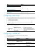
Task Remarks Configuring a WLAN ACL Configuring a WLAN-AP ACL Required. Configuring a basic ACL Configure at least one task. Configuring an advanced ACL Applicable to IPv4 and IPv6. Configuring an Ethernet frame header ACL Optional. Copying an ACL Applicable to IPv4 and IPv6. Configuring a time range You can create a maximum of 256 time ranges, each having a maximum of 32 periodic statements and 12 absolute statements.
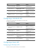
Step Command 4. Set the rule numbering step. step step-value 5. Create or edit a rule. rule [ rule-id ] { deny | permit } [ ssid ssid-name ] Remarks Optional. The default setting is 5. By default, WLAN ACL 199 contains rule 65534. This rule denies packets from WLAN clients. Optional. 6. Add or edit a rule comment. rule rule-id comment text 7. Add or edit a rule range remark. rule [ rule-id ] remark text By default, no rule comments are configured. Optional.
To configure an IPv4 basic ACL: Step Command Remarks Enter system view. system-view N/A Create an IPv4 basic ACL and enter its view. acl number acl-number [ name acl-name ] [ match-order { auto | config } ] Configure a description for the IPv4 basic ACL. description text Set the rule numbering step. step step-value 5. Create or edit a rule. rule [ rule-id ] { deny | permit } [ counting | source { source-address source-wildcard | any } | time-range time-range-name ] * 6.
Step Command Remarks By default, an IPv6 basic ACL does not contain any rule. 5. Create or edit a rule. rule [ rule-id ] { deny | permit } [ counting | routing [ type routing-type ] | source { source-address source-prefix | source-address/source-prefix | any } | time-range time-range-name ] * 6. Add or edit a rule comment. rule rule-id comment text Add or edit a rule range remark. rule [ rule-id ] remark text 7. Optional. By default, no rule comments are configured. Optional.
Step Command Remarks 5. Create or edit a rule.
Step Command Remarks Optional. Set the rule numbering step. step step-value 5. Create or edit a rule.
Step Command Remarks 5. Create or edit a rule. rule [ rule-id ] { deny | permit } [ cos vlan-pri | counting | dest-mac dest-address dest-mask | { lsap lsap-type lsap-type-mask | type protocol-type protocol-type-mask } | source-mac source-address source-mask | time-range time-range-name ] * 6. Add or edit a rule comment. rule rule-id comment text Add or edit a rule range remark. rule [ rule-id ] remark text 7. By default, an Ethernet frame header ACL does not contain any rule.
Displaying and maintaining ACLs Task Command Remarks Display configuration and match statistics for WLAN, WLAN-AP, IPv4 basic, IPv4 advanced, and Ethernet frame header ACLs. display acl { acl-number | all | name acl-name } [ | { begin | exclude | include } regular-expression ] Available in any view. Display configuration and match statistics for IPv6 basic and IPv6 advanced ACLs.
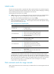
Figure 1 Network diagram Configuration procedure 1. Create a periodic time range from 8:00 to 18:00 on working days. system-view [AC] time-range trname 8:00 to 18:00 working-day 2. Define an ACL to control access to the salary server: # Create an advanced IPv4 ACL numbered 3000 and enter its view. [AC] acl number 3000 # Create a rule to permit packets to the salary server in the time range. [AC-acl-adv-3000] rule 0 permit ip source any destination 192.168.1.2 0.0.0.
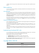
IPv6 ACL configuration example Network requirements Perform IPv6 packet filtering in the inbound direction of interface WLAN-ESS 1 on AC to deny all IPv6 packets but those with source addresses in the range 4050::9000 to 4050::90FF. Figure 2 Network diagram Configuration procedure # Create IPv6 ACL 2000, and create a rule for the ACL. system-view [AC] acl ipv6 number 2000 [AC-acl6-basic-2000] rule permit source 4050::9000 120 [AC-acl6-basic-2000] quit # Configure a traffic classifier.
QoS overview In data communications, Quality of Service (QoS) is a network's ability to provide differentiated service guarantees for diversified traffic. This refers to bandwidth, delay, jitter, and drop rate. Network resources are scarce. The contention for resources requires that QoS prioritize important traffic flows over trivial ones. For example, when bandwidth is fixed, more bandwidth for one traffic flow means less bandwidth for the other traffic flows.
QoS techniques overview The QoS techniques include traffic classification, traffic policing, rate limit, and congestion avoidance. The following section briefly introduces these QoS techniques.
Figure 4 QoS processing flow 16
QoS configuration approaches You can configure QoS by using the following approaches: • MQC approach • Non-MQC approach Some features support both approaches, but some support only one. For example: • You can configure traffic policing by using either the MQC approach or non-MQC approach. • You can configure the rate limit by using the non-MQC approach only. MQC approach In the modular QoS configuration (MQC) approach, you configure QoS service parameters by using QoS policies.
Figure 5 QoS policy configuration procedure Define a class Define a behavior Define a policy Apply the policy To interfaces To online users Defining a class Step 1. Enter system view. Command Remarks system-view N/A By default, the operator of a class is AND. 2. Create a class and enter class view. traffic classifier classifier-name [ operator { and | or } ] The operator of a class can be AND or OR.
Defining a traffic behavior A traffic behavior is a set of QoS actions (such as traffic filtering, shaping, policing, and priority marking) to take on a class of traffic. To define a traffic behavior: Step Command Remarks 1. Enter system view. system-view N/A 2.
Applying the QoS policy to an interface A policy can be applied to multiple interfaces, but only one policy can be applied in one direction (inbound or outbound) of an interface. The QoS policy applied to the outgoing traffic on an interface does not regulate local packets. Local packets refer to critical protocol packets sent by the local system for operation maintenance. The most common local packets include link maintenance and SSH packets. To apply the QoS policy to an interface: Step Enter system view.
Step 5. Activate the user profile. Command Remarks user-profile profile-name enable By default, user profiles are inactive. Displaying and maintaining QoS policies Task Command Remarks Display traffic class configuration. display traffic classifier { system-defined | user-defined } [ classifier-name ] [ | { begin | exclude | include } regular-expression ] Available in any view. Display traffic behavior configuration.
Configuring priority mapping Overview When a packet arrives, depending on your configuration, a device assigns a set of QoS priority parameters to the packet based on either of the following: • A certain priority field carried in the packet. • The port priority of the incoming port. This process is called "priority mapping." During this process, the device can modify the priority of the packet depending on device status.
802.11e priority Local precedence 2 1 3 3 4 4 5 5 6 6 7 7 Table 3 The default dot1p-lp priority mapping table 802.1p priority Local precedence 0 2 1 0 2 1 3 3 4 4 5 5 6 6 7 7 Table 4 The default dscp-lp priority mapping table DSCP Local precedence 0 to 7 0 8 to 15 1 16 to 23 2 24 to 31 3 32 to 39 4 40 to 47 5 48 to 55 6 56 to 63 7 Table 5 The default lp-dot1p priority mapping table Local precedence 802.
Local precedence 802.1p priority 5 5 6 6 7 7 Table 6 The default port priority-to-local priority mapping table Port priority Local precedence 0 0 1 1 2 2 3 3 4 4 5 5 6 6 7 7 Table 7 The default lp-dscp priority mapping table Local precedence dscp 0 0 1 8 2 16 3 24 4 32 5 40 6 48 7 56 Priority mapping configuration tasks You can configure priority mapping by using any of the following approaches: • Configuring priority trust mode.
Task Remarks Configuring a priority mapping table Optional. Configuring a port to trust packet priority for priority mapping Optional. Configuring a priority mapping table The device provides the following types of priority mapping table. Table 8 Priority mapping tables Priority mapping Description dot11e-lp 802.11e-local mapping table. dot1p-lp 802.1p-local mapping table. dscp-lp DSCP-local mapping table. lp-dot11e Local-802.11e mapping table. lp-dot1p Local-802.1p mapping table.
Step Enter system view. 1. Command Remarks system-view N/A • Enter interface view: Enter interface view or port group view. 2. interface interface-type interface-number • Enter port group view: port-group manual port-group-name Configure the trusted packet priority type for the interface. 3. Settings in Ethernet interface view take effect on the Ethernet interface. Settings in WLAN-ESS interface view take effect on all WLAN-DBSS interfaces created on the WLAN-ESS interface.
Step 2. Enter interface view or port group view. Command Remarks • Enter interface view: Settings in interface view (Ethernet or WLAN-ESS) take effect on the current interface. Settings in port group view take effect on all ports in the port group. interface interface-type interface-number • Enter port group view: port-group manual port-group-name 3. Set the port priority of the interface. qos priority priority-value The default is 0.
Figure 6 Network diagram Configuration procedure # Enter system view. system-view # Configure Ten-GigabitEthernet 1/0/1 to use the 802.1p priority of incoming packets for priority mapping. [AC] interface ten-gigabitethernet 1/0/1 [AC-Ten-GigabitEthernet1/0/1] qos trust dot1p [AC-Ten-GigabitEthernet1/0/1] quit # Configure Ten-GigabitEthernet 1/0/2 to use the 802.1p priority of incoming packets for priority mapping.
4 : 4 5 : 5 6 : 6 7 : 7 Verifying the configuration Use a PC to send flows with different priorities to the wireless clients connected to the three APs. After these packets enter the AC, their priorities are mapped to different priorities. You can determine the 802.11e priority of each flow by capturing the packets sent out of Ten-GigabitEthernet 1/0/1 and Ten-GigabitEthernet 1/0/2 to different APs.
[AC-wlan-st-1] ssid office1 [AC-wlan-st-1] bind wlan-ess 1 # Enable service template 1. [AC-wlan-st-1] service-template enable [AC-wlan-st-1] quit # Configure the port priority of WLAN-ESS 2 as 3. [AC] interface WLAN-ESS 2 [AC-WLAN-ESS2] qos priority 3 [AC-WLAN-ESS2] quit # Disable service template 2 before binding it with interface WLAN-ESS 2.
Configuring traffic policing and rate limit Overview Traffic policing, traffic shaping, and rate limit are QoS techniques that help assign network resources, such as assign bandwidth. They increase network performance and user satisfaction. For example, you can configure a flow to use only the resources committed to it in a certain time range. This avoids network congestion caused by burst traffic. Traffic policing limits the traffic rate and resource usage according to traffic specifications.
• EBS—Size of bucket E, which specifies the transient burst of traffic that bucket E can forward. CBS is implemented with bucket C, and EBS with bucket E. In each evaluation, packets are measured against the following bucket scenarios: • If bucket C has enough tokens, packets are colored green. • If neither bucket C nor bucket E has sufficient tokens, packets are colored red. Traffic policing Traffic policing supports policing the inbound and outbound traffic.
all packets to be sent through the interface are handled by the token bucket for rate limiting. If enough tokens are in the token bucket, you can forward the packets. Otherwise, packets are put into QoS queues for congestion management. In this way, the traffic passing the physical interface is controlled. Figure 9 Rate limit implementation The token bucket mechanism limits traffic rate when accommodating bursts. It allows bursty traffic to be transmitted if enough tokens are available.
Step Command Remarks 2. Create a class and enter class view. traffic classifier classifier-name [ operator { and | or } ] N/A 3. Configure match criteria. if-match match-criteria N/A 4. Return to system view. quit N/A 5. Create a behavior and enter behavior view. traffic behavior behavior-name N/A 6. Configure a traffic policing action.
Step Command Remarks 4. Return to system view. quit N/A 5. Activate the user profile. user-profile profile-name enable By default, user profiles are inactive. If a user profile is activated, you cannot modify or remove the CAR policy applied to it. For more information about user profiles, see Security Configuration Guide. Configuring the rate limit The rate limit of a physical interface specifies the maximum rate of incoming packets or outgoing packets. To configure the rate limit: Step 1.
aggregate interfaces, make sure their permitted VLANs are the same. HP also recommends that you set their link type to be the same. Network requirements As shown in Figure 10, perform traffic control for packets that the AC receives from Client A and Client B as follows: • Limit the rate of packets from Client A to 54 kbps: { { When the traffic rate is below 54 kbps, the traffic is forwarded. When the traffic rate exceeds 54 kbps, the excess packets are marked with local precedence 2, and then forwarded.
[AC-behavior-tb2] car cir 500 cbs 32000 ebs 0 green pass red discard [AC behavior-tb2] quit [AC] qos policy qp [AC-qospolicy-qp] classifier tc1 behavior tb1 [AC-qospolicy-qp] classifier tc2 behavior tb2 [AC-qospolicy-qp] quit # Apply QoS policy qp to the incoming traffic of interface WLAN-ESS 1. [AC]interface WLAN-ESS 1 [AC-WLAN-ESS1]qos apply policy qp inbound [AC-WLAN-ESS1]quit # Configure QoS policy qp3 to perform traffic policing for the traffic from the AC to the Internet.
Configuring congestion management Overview Causes, impacts, and countermeasures of congestion Congestion occurs on a link or node when traffic size exceeds the processing capability of the link or node. It is typical of a statistical multiplexing network, and can be caused by link failures, insufficient resources, and various other causes. Figure 11 shows some common congestion scenarios.
FIFO Figure 12 FIFO queuing As shown in Figure 12, the first in first out (FIFO) uses a single queue and does not classify traffic or schedule queues. FIFO delivers packets depending on their arrival order, with the one arriving earlier scheduled first. The only concern of FIFO is queue length, which affects delay and packet loss rate. On a device, resources are assigned to packets depending on their arrival order and load status of the device. The best-effort service model uses FIFO queuing.
Priority queuing schedules the four queues in the descending order of priority. It sends packets in the queue with the highest priority first. When the queue with the highest priority is empty, it sends packets in the queue with the second highest priority. In this way, you can assign the mission-critical packets to the high priority queue to make sure they are always served first. The common service packets are assigned to the low priority queues, and transmitted when the high priority queues are empty.
Table 9 Congestion management technique comparison Type Number of queues Advantages Disadvantages • All packets are treated equally. The available bandwidth, delay and drop probability are determined by the arrival order of packets. • No need to configure, easy FIFO 1 to use. • Easy to operate, low delay. • No restriction on traffic from connectionless protocols (protocols without any flow control mechanism, UDP, for example).
Configuration example # Set the FIFO queue size to 100. system-view [Sysname] interface ten-gigabitethernet 1/0/1 [Sysname-Ten-GigabitEthernet1/0/1] qos fifo queue-length 100 [Sysname-Ten-GigabitEthernet1/0/1] quit [Sysname] interface ten-gigabitethernet 1/0/2 [Sysname-Ten-GigabitEthernet1/0/2] qos fifo queue-length 100 Configuring PQ You can define multiple rules for a priority queue list (PQL), and apply the list to an interface.
Step 8. Display the contents of the specific PQ list or all the PQ lists. Command Remarks display qos pql [ pql-number ] [ | { begin | exclude | include } regular-expression ] Optional. Available in any view. PQ configuration example The configuration examples were created on the 11900/10500/7500 20G unified wired-WLAN module and might vary by device model.
# Configure PQ list 1 to assign packets with local precedence value 5 to the top queue. [AC] qos pql 1 local-precedence 5 queue top # Set the maximum length to 1000 for the middle queue in PQ list 1. [AC] qos pql 1 queue middle queue-length 1000 # Apply PQ list 1 to interface Ten-GigabitEthernet 1/0/1 and configure the interface to use the 802.1p priority of received packets for priority mapping.
Step Command Remarks Configure the bytes sent from a queue during a cycle of round robin queue scheduling. qos cql cql-index queue queue-number serving byte-count Optional. 6. Enter interface view. interface interface-type interface-number N/A 7. Apply the CQ list to the interface. qos cq cql cql-index By default, FIFO applies. 8. Display interface CQ list configuration information.
# Apply CQ list 1 to interface Ten-GigabitEthernet1/0/1, and configure the interface to use the 802.1p priority of received packets for priority mapping.
Configuring traffic filtering You can filter in or filter out a class of traffic by associating the class with a traffic filtering action. For example, you can filter packets sourced from a specific IP address according to network status. Configuration procedure To configure traffic filtering: Step Command Remarks 1. Enter system view. system-view N/A 2. Create a class and enter class view. traffic classifier classifier-name [ operator { and | or } ] N/A 3. Configure match criteria.
When configuring the 11900/10500/7500 20G unified wired-WLAN module, make sure the settings are correct (including VLAN settings) on the internal Ethernet interface that connects the module to the switch. For more information, see HP 11900/10500/7500 20G Unified Wired-WLAN Module Basic Configuration Guide. By default, the aggregate interfaces between the access controller engine and the switching engine on an 830 switch or an 870 appliance are Access interfaces in VLAN 1.
Configuring priority marking Priority marking sets the priority fields or flag bits of packets to modify the priority of traffic. For example, you can use priority marking to set IP precedence or DSCP for a class of IP traffic to change its transmission priority in the network. To configure priority marking, associate a class with a behavior configured with the priority marking action to set the priority fields or flag bits of the class of packets.
Priority marking configuration example The configuration examples were created on the 11900/10500/7500 20G unified wired-WLAN module and might vary by device model. When configuring the 11900/10500/7500 20G unified wired-WLAN module, make sure the settings are correct (including VLAN settings) on the internal Ethernet interface that connects the module to the switch. For more information, see HP 11900/10500/7500 20G Unified Wired-WLAN Module Basic Configuration Guide.
system-view [AC] acl number 3000 [AC-acl-adv-3000] rule permit ip destination 192.168.0.1 0 [AC-acl-adv-3000] quit # Create advanced ACL 3001, and configure a rule to match packets with destination IP address 192.168.0.2. [AC] acl number 3001 [AC-acl-adv-3001] rule permit ip destination 192.168.0.2 0 [AC-acl-adv-3001] quit # Create advanced ACL 3002, and configure a rule to match packets with destination IP address 192.168.0.3. [AC] acl number 3002 [AC-acl-adv-3002] rule permit ip destination 192.
[AC-qospolicy-policy_server] classifier classifier_fserver behavior behavior_fserver [AC-qospolicy-policy_server] quit # Apply the policy named policy_server to the incoming traffic of interface WLAN-ESS1.
Appendix Appendix A Acronyms Table 10 Acronyms Acronym Full spelling AF Assured Forwarding BE Best Effort CAR Committed Access Rate CBS Committed Burst Size CIR Committed Information Rate CQ Custom Queuing DiffServ Differentiated Service DSCP Differentiated Services Code Point EBS Excess Burst Size EF Expedited Forwarding FIFO First in First out IntServ Integrated Service ISP Internet Service Provider PIR Peak Information Rate PQ Priority Queuing QoS Quality of Service RSVP
Appendix B Introduction to packet precedences IP precedence and DSCP values Figure 18 ToS and DS fields As shown in Figure 18, the ToS field in the IPv4 header contains eight bits, where the first three bits (0 to 2) represent IP precedence from 0 to 7. The Traffic Classes field in the IPv6 header contains eight bits, where the first three bits (0 to 2) represent IP precedence from 0 to 7.
DSCP value (decimal) DSCP value (binary) Description 22 010110 af23 26 011010 af31 28 011100 af32 30 011110 af33 34 100010 af41 36 100100 af42 38 100110 af43 8 001000 cs1 16 010000 cs2 24 011000 cs3 32 100000 cs4 40 101000 cs5 48 110000 cs6 56 111000 cs7 0 000000 be (default) 802.1p priority 802.1p priority lies in the Layer 2 header and applies when Layer 3 header analysis is not needed and QoS must be assured at Layer 2.
Figure 20 802.1Q tag header Table 13 Description on 802.1p priority 802.1p priority (decimal) 802.1p priority (binary) Description 0 000 best-effort 1 001 background 2 010 spare 3 011 excellent-effort 4 100 controlled-load 5 101 video 6 110 voice 7 111 network-management 802.11e priority To provide QoS services on WLAN, the 802.11e standard was developed. IEEE 802.11e is a MAC-layer enhancement to IEEE 802.11. IEEE 802.11e adds a 2-byte QoS Control field to the 802.
Support and other resources Contacting HP For worldwide technical support information, see the HP support website: http://www.hp.
Conventions This section describes the conventions used in this documentation set. Command conventions Convention Description Boldface Bold text represents commands and keywords that you enter literally as shown. Italic Italic text represents arguments that you replace with actual values. [] Square brackets enclose syntax choices (keywords or arguments) that are optional. { x | y | ... } Braces enclose a set of required syntax choices separated by vertical bars, from which you select one.
Network topology icons Represents a generic network device, such as a router, switch, or firewall. Represents a routing-capable device, such as a router or Layer 3 switch. Represents a generic switch, such as a Layer 2 or Layer 3 switch, or a router that supports Layer 2 forwarding and other Layer 2 features. Represents an access controller, a unified wired-WLAN module, or the switching engine on a unified wired-WLAN switch. Represents an access point.
Index ACDMNOPQRT Displaying and maintaining ACLs,11 A Displaying and maintaining priority mapping,27 ACL configuration examples,11 Displaying and maintaining traffic policing and rate limit,35 Appendix A Acronyms,53 Appendix B Introduction to packet precedences,54 M C MQC approach,17 Changing the port priority of an interface,26 N Configuration procedure,49 Configuration procedure,47 Non-MQC approach,17 Configuration task list,3 O Configuration task list,33 Overview,22 Configuring a basic A